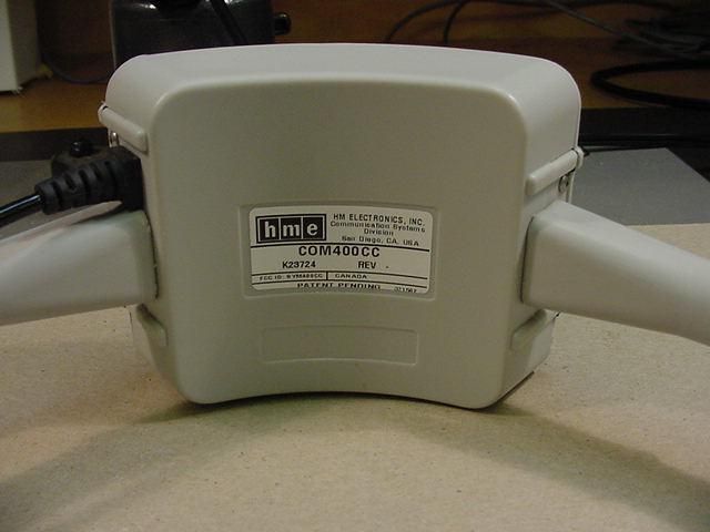
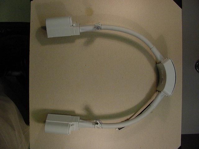
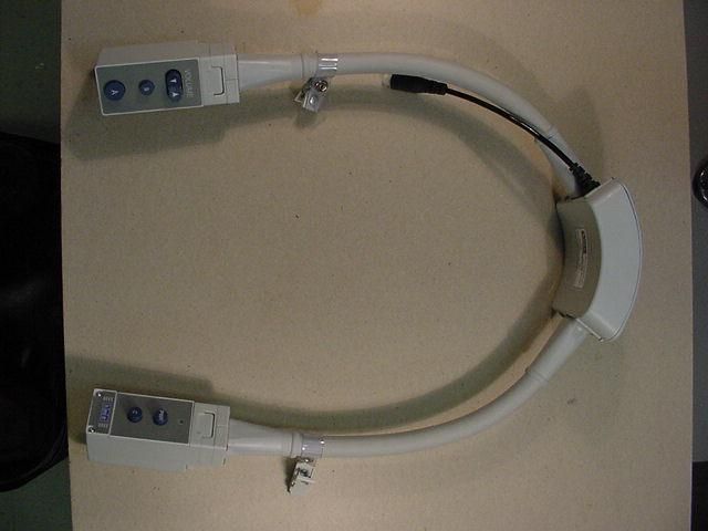
BYM400CCCOM400CC Communicator
HM Electronics Inc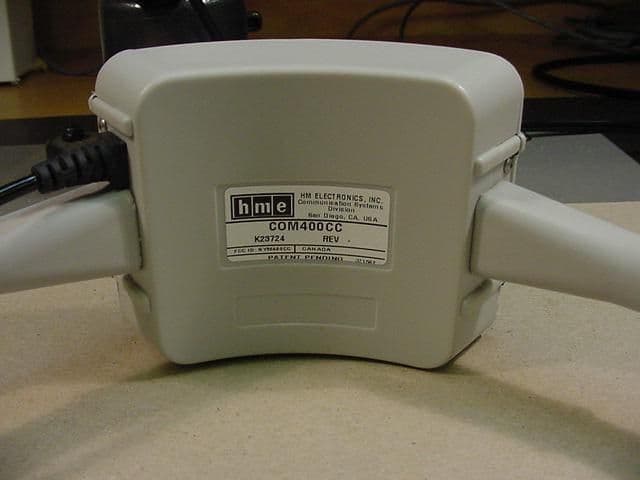
Click to zoom
Application Details
- Equipment Class
- TNT - Licensed Non-Broadcast Transmitter Worn on Body
- Date of Grant
- Apr 05, 2001
- Application Purpose
- Original Equipment
- Date of Application
- Dec 13, 2000
- Equipment Note
- COM400CC Communicator
- Frequency Range
- 468.48750000 - 469.88750000
- Company
- HM Electronics Inc
- Country
- United States
Documents & Files
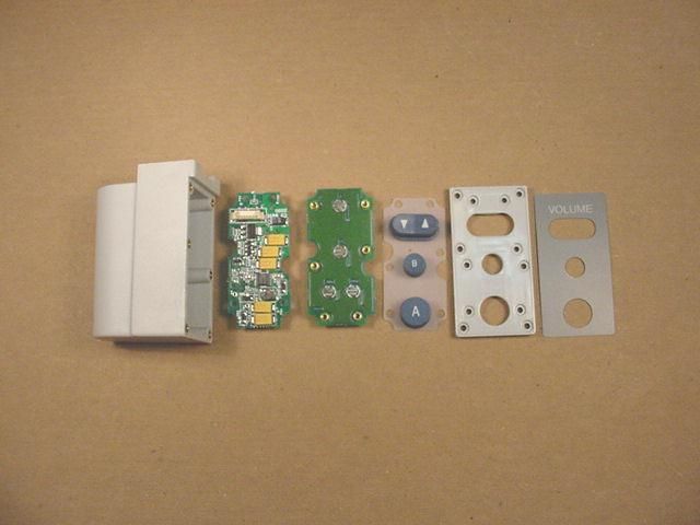
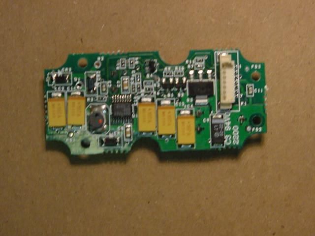
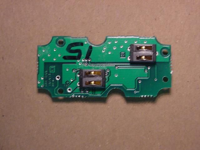
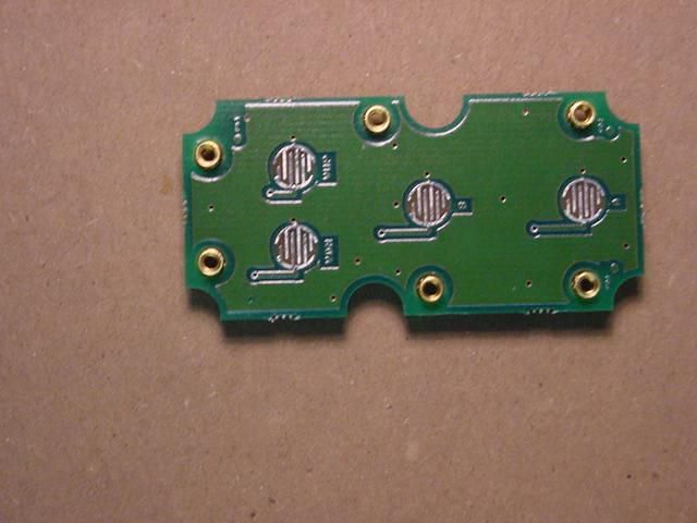
Document Text
Text extracted from the exhibit documents filed with the FCC. Open a document above to read the original.
Attestation Statements
ATTESTATION STATEMENT: All tests according to FCC Part 2, Paragraphs 2.1053, 2.1049, 2.1051; and Part 90, Paragraph 90.217* were n - Performed o - Not Performed The Equipment Under Test n - Fulfills the FCC Part 2, Paragraphs 2.1053, 2.1049, 2.1051; and Part 90, Paragraph 90.217* requirements. _______________________ - TÜV PRODUCT SERVICE, INC. - Responsible Engineer: Jim Owen (EMC Engineer) (*) 2.1055 tests performed by HM Electronics. See Attestation Statement.
RF Exposure Info
---------- From: Kwok Chan <[email protected]>, on 12/4/00 10:19 AM: To: Mary Washington@EMC@PSSDG It is categorically excluded from routine RF exposure evaluation to show compliance. If SAR evaluation is needed with respect to 1.1307(d), it will need to be determined based on information in the filing >>> Mary Washington <[email protected]> 12/04/00 12:40PM >>> The rule part is part 90. The device is worn around the user's neck. Mary Washington EMC Engineer/Telecommunication Certification Body Technical Certifier 1-858-546-3999 Phone 1-858-546-0364 Fax http://www.tuvglobal.com/tcb ---------- Original Text ---------- From: Kwok Chan <[email protected]>, on 12/4/00 9:29 AM: Looking at the frequency, it appears this device could be one of those on the categorically excluded list of 2.1093. Without knowing the exact rule part this device will operate, I cannot give you an exact answer. Even if categorically excluded, we will need info on operating configurations and exposure conditions in the filing to determine if compliance can be ensured or SAR will need to be requested with respect to 1.1307(d), mainly for the 50 mW output. >>> Mary Washington <[email protected]> 12/04/00 12:15PM >>> Dear Mr. Chan, We have a client that manufacturers a collar communicator that is used in fast food restaurants operating on a frequency of 468 to 469 MHz and output transmit power of 1, 10, 50 mW (factory selectable). Does this device require SAR measurements? If you need additional information or have any questions, contact me. Thanking you in advance for your assistance in this matter, Mary Washington EMC Engineer 1-858-546-3999 Phone 1-858-546-0364 Fax http://www.tuvglobal.com
RF Exposure Info
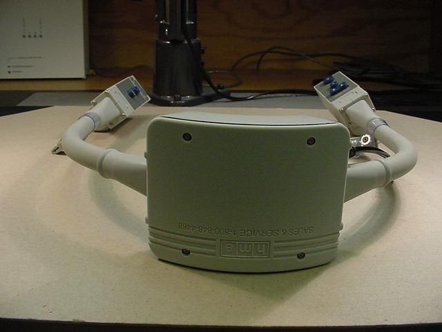
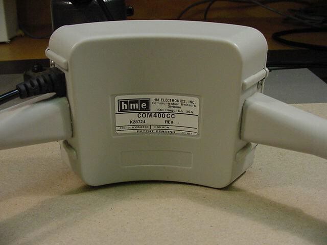
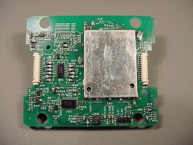
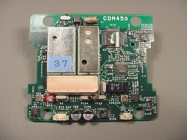
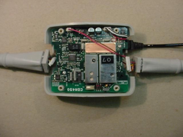
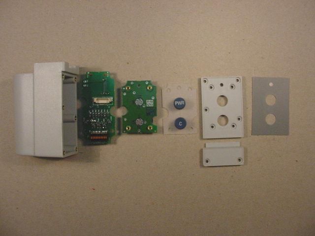
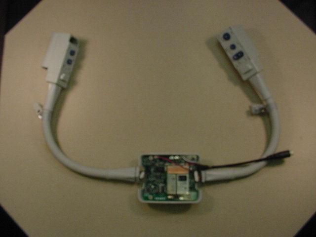
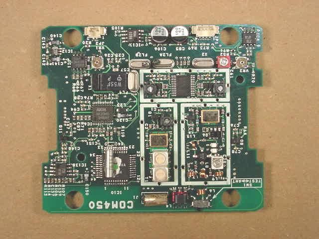
To: Judy Evans TUV Technical Writer Mary Washington TUV EMC Engineer, TCB Certifier From: Seth Schlam HM Electronics, Sustaining Engineer Subject: FCC Application for COM400CC, FCC ID: BYM400CC Judy, This is in reply to the questions on the COM400CC transceiver (FCC ID BYM400CC) submitted by Joe Dichoso of the FCC Application Processing Branch, in FCC correspondence reference number 18315 of 8 March 2001. Question 1 was: Supply information on the antenna. Where it is located and how close it is to the user. Reply: The antenna is a quarter wave monopole antenna with approximately 0 dB gain. Physically it is a copper trace on the transceiver printed circuit board (PCB). The photo below shows the antenna. The transceiver printed circuit assembly itself is called the COM450. The antenna trace starts under Switch 1 near L4 (the copper inductor). This is near the tip of the white arrow in the upper left portion of the photo. It goes to the left of the photo, curves upward in a semicircle, and goes back to the right near the top edge of the board. Question 2 was: Why is it one inch from the user when under such operating conditions? Reply: The antenna is in a fixed position within the transceiver, being a trace on the PCB. The BYM400CC is called a “Collarcom” which means that it is a communications device worn around the collar as shown in the photo below. In the photo the rear plastic cover is removed from the COM400CC so the transceiver PCB is visible. Since the PCB is at the top of the case, which is 1 inch thick, and the case stands off a short distance from the users collar (about one quarter inch), the antenna is about one inch (conservative estimate) from the user. There are no multiple configurations or actions the user can take to vary this distance. When the COM400CC is being used, the antenna is always one inch from the user. The operating manual describes normal wearing and use of the COM400CC Collarcom, and there is really nothing the user could do that could get the antenna placed closer than one inch from themselves. Compliance with requirement for RF exposure to humans. Maximum output power of the COM400CC is 50 mW (milliwatts) Surface area of sphere at one inch (2.54 cm) from the user is 81.07 square cm. Therefore power density at max transmit power is 50/81.07 = .61 mW per square cm. This complies with Table 1 of the FCC Office of Engineering and Technology (OET) Bulletin 56 Entitled FCC limits for Maximum Permissible Exposure under Part (A) Limits for Occupational/ Controlled Exposure. The Frequency of the COM400CC is 468 MHz, so the Table 1 part A limit is f/300 or 1.56 mW per square cm. The unit under very worst case is .61 mW per square cm. Two further points could be made to demonstrate compliance. First, the table allows six minute time averaging, and it is estimated that significantly less than half of any six minutes would be in the transmit mode. Second, the COM400CC is usually used at lower power settings than the 50mW, although it is capable of that level. It is selectable to 1, 10, or 50 mW. Since the unit complies with OET Bulletin 56 table 1A limits for power density, at 468 MHz, under maximum power at 100% duty cycle we feel that the unit complies with FCC limits for Maximum Permissible Exposure (MPE).
Test Report
Report No. 0411-08 (FCC ID: BYM400CC) Page 1 Rev.No 1.0 MEASUREMENT AND TECHNICAL REPORT HM ELECTRONICS 6675 Mesa Ridge Road San Diego, CA 92121-2937 DATE: 05 December 2000 This Report Concerns:Original Grant: XClass II Change: Equipment Type:COM400CC, Model K23724 Deferred grant requested per 47 CFR 0.457(d)(1)(ii)?Yes: Defer until: No: X Company Name agrees to notify the Commission by:N/A of the intended date of announcement of the product so that the grant can be issued on that date. Transition Rules Request per 15.37?Yes:*No: (*) FCC Part 2, Paragraphs 2.1053, 2.1049, 2.1051; and Part 90, Paragraph 90.217 Report Prepared by: TÜV PRODUCT SERVICE 10040 Mesa Rim Road San Diego, CA 92121-2912 Phone: 858 546 3999 Fax: 858 546 0364 Report No. 0411-08 (FCC ID: BYM400CC) Page 2 Rev.No 1.0 TABLE OF CONTENTS Pages 1 GENERAL INFORMATION3 1.1Product Description3 1.2Related Submittal Grant4 1.3Tested System Details4 1.4Test Methodology5 1.5Test Facility5 1.6Part 2 Requirements6 2 SYSTEM TEST CONFIGURATION7 2.1Justification7 2.2EUT Exercise Software7 2.3Special Accessories7 2.4Equipment Modifications7 2.5Configuration of Tested System7 3RADIATED EMISSION DATA8 3.1Field Strength Calculation13 4 CONDUCTED EMISSION DATA 14 5Signature Page49 Report No. 0411-08 (FCC ID: BYM400CC) Page 3 Rev.No 1.0 1 GENERAL INFORMATION 1.1Product Description Components of EUT DescriptionModel NumberSerial NumberFCC ID Number Collar Communicator COM400CC K23724--BYMCOM400CC OPERATING MODE(S):Normal I/O CABLES Headset connector, analog, (1), No shielding; 5-pin custom connector; audio port termination; appx. 1’ cable; removable POWER CORDS N/A, battery operated POWER INTERFACE FREQUENCY/AC/DC VOLTAGE:Battery, DC INTERFACING AND/OR SIMULATORS PERIPHERAL EQUIPMENT: DESCRIPTIONMODEL #SERIAL #FCC ID HeadsetHS11--None Report No. 0411-08 (FCC ID: BYM400CC) Page 4 Rev.No 1.0 1 GENERAL INFORMATION (continued) 1.2Related Submittal/Grant None 1.3Tested System Details The FCC IDs for all equipment, plus descriptions of all cables used in the tested system are: None Report No. 0411-08 (FCC ID: BYM400CC) Page 5 Rev.No 1.0 1.4Test Methodology Purpose of Test:To demonstrate compliance with the ANSI C63.4 setup. Test Performed:x1. Conducted Emissions, FCC Part 2, Paragraphs 2.1049, 2.1051, & Part 90, Paragraph 90.217 2. Radiated Emissions, EN55022: 1992 Class B limit, 30 - 1,000 MHz, 10 meters x3. Radiated Emission per FCC Part 2, Paragraph 2.1053 4. Engineering evaluations 1.5Test Facility The open area test site and conducted measurement data were tested by: TÜV PRODUCT SERVICE 10040 Mesa Rim Road San Diego, CA 92121-2912 Phone: 619 546 3999 Fax: 619 546 0364 The Test Site Data and performance comply with ANSI 63.4 and are registered with the FCC, 7435 Oakland Mills Rd, Columbia Maryland 21046. All Measurement Data is acquired according to the content of FCC Measurement Procedure and ANSI C63.4, unless supplemented with additional requirements as noted in the test report. Report No. 0411-08 (FCC ID: BYM400CC) Page 6 Rev.No 1.0 1.6 Part 2 Requirements Frequency Range: Transmit: 468.4875 to 469.8875 MHz Receive: 457.5125 to 467.6125 MHz Maximum Power Rating: 50 mW DC Voltages applied to dc currents into the final radio frequency amplifying device for normal operation over the power range: Final gain stage on the transmit strip is Q5. Q5 collector is 5 Vdc Q5 collector I is 20 mAValues at 50 mW power rating. 50 mW is the only setting that is used. Q5 base is 3.5 Vdc Q5 base I is 1 mA Description of all circuitry and devices provdied for determining and stabilizing frequency: Transmit frequency is determined by phase locked loop on the 1st mixer (IC2) IC on the transceiver board. See writeup on transceiver board theory of operation. Description of circuits or devices employed for suppression of spurious radiation, for limiting modulation, and for limiting power: Modulation is limited by the AK2345 tone chip IC6 on the transceiver board. The IC has an internal limiter circuit. Power is limited by the supply voltage. Spurious signals are suppressed by saw filter (FL3) and by out filter (L7, L8, L9, C32, C33, C37, C38, C39). Report No. 0411-08 (FCC ID: BYM400CC) Page 7 Rev.No 1.0 2.SYSTEM TEST CONFIGURATION 2.1Justification The COM400CC, Model K23724 was initially tested for FCC emission in the following configuration: See Block Diagram. 2.2EUT Exercise Software None 2.3Special Accessories None 2.4Modification None 2.5Configuration of Tested System See Block Diagram. Report No. 0411-08 (FCC ID: BYM400CC) Page 8 Rev.No 1.0 3RADIATED EMISSION DATA/EQUIPMENT The following data lists the significant emission frequencies, measured levels, correction factor (which includes cable and antenna corrections), the corrected reading, and the limit. See following page(s). Report No. 0411-08 (FCC ID: BYM400CC) Page 12 Rev.No 1.0 Emissions Test Conditions: RADIATED SPURIOUS EMISSIONS The measurements were performed at the following test location : o - Test not applicable n - Roof (Small Open Area Test Site) o - Canyon #1 (10- and 30-Meter Open Area Test Site), Carroll Canyon, San Diego o - Canyon #2 (3- and 10-Meter Open Area Test Site), Carroll Canyon, San Diego Testing was performed at a test distance of: o - 1 meters n - 3 meters o - 10 meters Test Equipment Used : Model #ManufacturerDescriptionSerial #Prop. #Cal Date 8566BHewlett PackardSpectrum Analyzer2311A0220940711/01 85662BHewlett PackardSpectrum Analyzer Display2309A0468240611/01 LPB2520/AAntenna ResearchLPB116973805/01 ESVS30Rhode & SchwarzReceiver833825/00346612/00 Remarks: Report No. 0411-08 (FCC ID: BYM400CC) Page 13 Rev.No 1.0 3.1Field Strength Calculation If a preamplifier was used during the Radiated Emission Testing, it is required that the amplifier gain must be subtracted from the Spectrum Analyzer (Meter) Reading. In addition, a correction factor for the antenna , cable used and a distance factor, if any, must be applied to the Meter Reading before a true field strength reading can be o…
Text truncated - open the document above for the full version.
Test Setup Photos
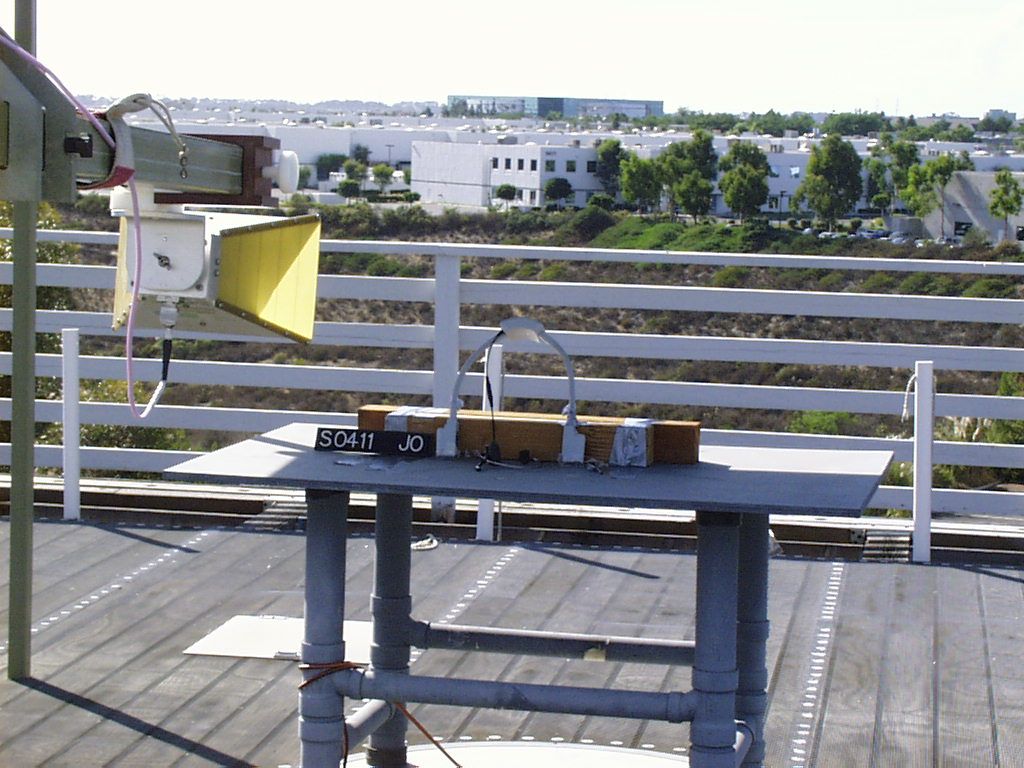
Spectrum Analyzer EUT Test Setup
Contact Information
Applicant
Manuel Liong Jr(Staff Regulatory Engineer)
Technical Contact
TUV Product ServiceJudy F Evans
[email protected]858 546 3999
10040 Mesa Rim Road · San Diego, California · United States
Non-Technical Contact
TUV Product ServiceJudy F Evans
[email protected]858 546 3999
Test Firm
TUV AmericaJames Owen
Technical Specifications
| # | Rule Parts | Frequency Range | Power Output | Emission | Tolerance |
|---|---|---|---|---|---|
| 1 | 90 | 468.4875 MHz - 469.8875 MHz | 45.40 mW | 11K2F3E | 10.8600000000 ppm |
Other Applications from HM Electronics Inc
BYMBP5GC1
Apr 23, 2026Wireless Beltpack
Equipment Class
CBE - Citizens Band End User Devices
BYM7000A
Aug 12, 2024Remote Transceiver
Equipment Class
NII - Unlicensed National Information Infrastructure TX
BYM7000
Mar 15, 2021Remote Transceiver
Equipment Class
NII - Unlicensed National Information Infrastructure TX
BYM7002
Mar 15, 2021Nexeo AIO headset
Equipment Class
DTS - Digital Transmission System
BYM-AC70
Dec 20, 2020Battery Charger
Equipment Class
DTS - Digital Transmission System