BYMXCVR2G4AWireless Intercom System
HM Electronics Inc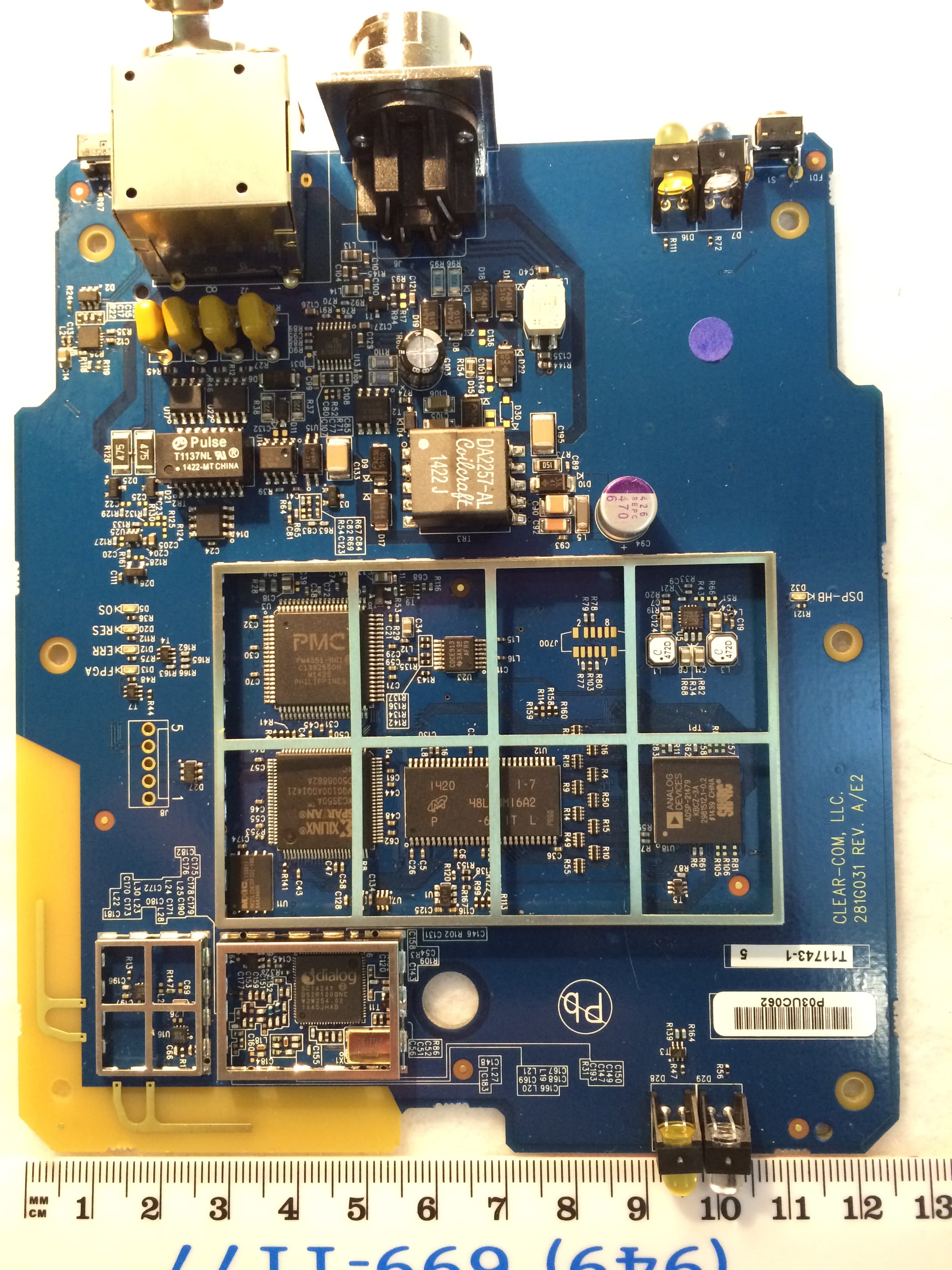
Click to zoom
Application Details
- Equipment Class
- DSS - Part 15 Spread Spectrum Transmitter
- Date of Grant
- Apr 07, 2015
- Application Purpose
- Original Equipment
- Date of Application
- Apr 07, 2015
- Equipment Note
- Wireless Intercom System
- Frequency Range
- 2403.64800000 - 2479.68000000
- Company
- HM Electronics Inc
- Country
- United States
Documents & Files
Document Text
Text extracted from the exhibit documents filed with the FCC. Open a document above to read the original.
Users Manual
FreeSpeak II™ Base Station Version Part Number: 399G087 Rev 21 Date: December 19, 2014 User Guide User Guide | FreeSpeak II™ Page 2 Document Reference Clear-Com FreeSpeak II User Guide Part Number: 399G087 Revision: 21 Legal Disclaimers Copyright © 2014 HME Clear-Com Ltd. All rights reserved. Clear-Com and the Clear-Com logo are registered trademarks of HM Electronics, Inc. The software described in this document is furnished under a license agreement and may be used only in accordance with the terms of the agreement. The product described in this document is distributed under licenses restricting its use, copying, distribution, and decompilation/reverse engineering. No part of this document may be reproduced in any form by any means without prior written authorization of Clear-Com, an HME Company. Clear-Com Offices are located in California, USA; Cambridge, UK; Dubai, UAE; Montreal, Canada; and Beijing, China. Specific addresses and contact information can be found on Clear-Com’s corporate website: www.clearcom.com Clear-Com Contacts Americas and Asia-Pacific Headquarters C alifornia, United States Tel: +1.510.337.6600 Email: [email protected] E urope, Middle East, and Africa Headquarters Cambridge, United Kingdom Tel: +44 1223 815000 Email: [email protected] Canada Office Quebec , Canada Tel: +1 (450) 653-9669 China Office Beijing Representative Office User Guide | FreeSpeak II™ Page 3 Beijing, P.R.China Tel: +8610 65811360 / 65815577 Contents Document Reference ................................. .............................................. 2 1 Important Safety instructions ............................................. 10 1.1 Safety symbols ...................................................................... 11 2 Introduction to FreeSpeak II™ ............................................ 12 2.1 An FS II communication system ............................................... 13 2.1.1 FreeSpeak II system capacity ....................................................... 14 3 Installing a system .............................................................. 14 3.1 Placing the Base station .......................................................... 16 3.2 Placing the antennas and splitters ............................................ 16 3.2.1 Wiring the antennas and splitters ................................................. 17 3.2.2 Power supplies to the components of an FS II System ..................... 18 3.2.3 Determining coverage areas......................................................... 19 3.3 Doing a site survey to determine coverage areas ........................ 20 3.3.1 Doing a site survey with a beltpack ............................................... 20 3.3.2 Testing antenna handoff .............................................................. 22 3.3.3 Getting information on active antenna status ................................. 23 3.3.4 Assigning beltpacks to coverage areas........................................... 23 3.3.5 Conditions affecting coverage areas .............................................. 24 3.4 Registering beltpacks .............................................................. 24 3.4.1 Over the air (OTA) registration of a beltpack from the Base station ...................................................................................... 25 4 Connecting the Base station ................................................ 28 4.1 Understanding the Back-Panel Connectors ................................. 29 4.2 Connecting to partyline intercom systems ................................. 32 4.2.1 Clear-Com and compatible partyline .............................................. 32 4.2.2 Connecting directly to Clear-Com partyline beltpacks ...................... 33 User Guide | FreeSpeak II™ Page 4 4.2.3 Connecting to an RTS™ wired beltpack .......................................... 34 4.2.4 Front-panel adjustments for partyline connections .......................... 34 4.2.5 Troubleshooting partyline connections ........................................... 35 4.3 Wireless partyline ................................................................... 37 4.4 Connecting to 4-Wire and digital matrix intercom ....................... 38 4.4.2 Connecting to Clear-Com matrix plus ............................................ 40 4.4.3 Connecting to Clear-Com Eclipse digital matrix ............................... 40 4.4.4 Connecting with other digital matrix intercom systems .................... 41 4.4.5 Connecting with other 4-wire devices ............................................ 41 4.5 Connecting to a program audio source ...................................... 42 4.6 IFB configuration .................................................................... 42 4.7 Connecting to the stage announce output .................................. 43 4.8 Connecting to a PC ................................................................. 44 4.8.1 Connecting using the serial port ................................................... 44 4.8.2 Connecting using the LAN port ..................................................... 46 4.9 Connecting to transceiver/antennas .......................................... 46 4.9.1 Connecting one transceiver/antenna directly to a transceiver port .......................................................................................... 46 4.9.2 Connecting transceiver/antennas with a splitter (PD2203) ............... 47 4.9.3 Powering an antenna or antenna splitter ........................................ 48 5 Operating the Base station .................................................. 49 5.1 Introduction ........................................................................... 49 5.2 Understanding Front-Panel Operation ........................................ 50 5.2.1 Call Channel A ............................................................................ 50 5.2.2 Call Channel B .............................................…
Text truncated - open the document above for the full version.
RF Exposure Info
Prediction of MPE limit at a given distance Equation from page 18 of OET Bulletin 65, Edition 97-01 where:S = power density P = power input to the antenna G = power gain of the antenna in the direction of interest relative to an isotropic radiator R = distance to the center of radiation of the antenna Maximum peak output power at antenna input terminal:19.60(dBm) Source-Based Time Averaging100.00(%) Corrected max peak output power:19.60(dBm) Maximum peak output power at antenna input terminal:91.20108(mW) Antenna gain(typical):3(dBi) Maximum antenna gain:1.995262(numeric) Prediction distance:20(cm) Prediction frequency:2481(MHz) MPE limit for uncontrolled exposure at prediction frequency:1(mW/cm^2) Power density at prediction frequency:0.036202(mW/cm^2) 2 4R PG S π =
Test Report
Nemko Test Report: 2015_276998_FCC_15247 Applicant: HM Electronics, Inc. 14110 Stowe Drive Poway, CA 92064 USA Equipment Under Test: XCVR2G4A (E.U.T.) FCC Identifier: BYMXCVR2G4A IC Identifier: 1860A-XCVR2G4A In A ccordance With: FCC Part 15, Subpart C, 15.247 and Industry Canada RSS-210, Issue 8 Frequency Hopping Transmitters T ested By: Nemko USA, Inc. 2210 Faraday Ave. Ste 150 Carlsbad, CA 92008 USA TESTED BY: DATE: 10 February 2015 David Light, Wireless Engineer APPROVED BY: DATE: 11 February 2015 Tom Tidwell, Nemko Reviewer Total Number of Pages: 40 Nemko USA, Inc. FCC PART 15, SUBPART C and Industry Canada RSS-210 Issue 8 FREQUENCY HOPPING SPREAD SPECTRUM TRANSMITTER EQUIPMENT: XCVR2G4A PROJECT NO.: 2015_276998_FCC_15247 Table of Contents SECTION 1. SUMMARY OF TEST RESULTS 3 SECTION 2. EQUIPMENT UNDER TEST (E.U.T.) 5 SECTION 3. CHANNEL SEPARATION 6 SECTION 4. TIME OF OCCUPANCY 12 SECTION 5. PEAK POWER OUTPUT 16 SECTION 6. SPURIOUS EMISSIONS (CONDUCTED) 20 SECTION 7. SPURIOUS EMISSIONS (RADIATED) 25 SECTION 8. POWERLINE CONDUCTED EMISSIONS 27 SECTION 9. TEST EQUIPMENT LIST 29 ANNEX A - TEST DETAILS 30 ANNEX B - TEST DIAGRAMS 38 Page 2 of 40 Nemko USA, Inc. FCC PART 15, SUBPART C and Industry Canada RSS-210 Issue 8 FREQUENCY HOPPING SPREAD SPECTRUM TRANSMITTER EQUIPMENT: XCVR2G4A PROJECT NO.: 2015_276998_FCC_15247 Section 1. Summary of Test Results Manufacturer: HM Electronics, Inc. Model No.: XCVR2G4A Serial No.: None General: All measurements are traceable to national standards. These tests were conducted on a sample of the equipment for the purpose of demonstrating compliance with Part 15, Subpart C, Paragraph 15.247 and Industry Canada RSS-210, Issue 8 for Frequency Hopping Spread Spectrum devices. Tests were conducted is accordance with ANSI C63.10: 2013 and FCC Public Notice DA 00- 705. Radiated emissions are made on an open area test site. A description of the test facility is on file with the FCC and Industry Canada. New Submission Production Unit Class II Permissive Change Pre-Production Unit THIS TEST REPORT RELATES ONLY TO THE ITEM(S) TESTED. THE FOLLOWING DEVIATIONS FROM, ADDITIONS TO, OR EXCLUSIONS FROM THE TEST SPECIFICATIONS HAVE BEEN MADE. See “ Summary of Test Data”. NVLAP Lab Code 200116-0 This report must not be used to claim product certification, approval, or endorsement by NVLAP, NIST, or any agency of the Federal Government. Nemko USA, Inc. is a NVLAP accredited laboratory. Nemko USA Inc. authorizes the above named company to reproduce this report provided it is reproduced in its entirety and for use by the company’s employees only. Any use which a third party makes of this report, or any reliance on or decisions to be made based on it, are the responsibility of such third parties. Nemko USA Inc. accepts no responsibility for damages, if any, suffered by any third party as a result of decisions made or actions based on this report. This report applies only to the items tested. Page 3 of 40 Nemko USA, Inc. FCC PART 15, SUBPART C and Industry Canada RSS-210 Issue 8 FREQUENCY HOPPING SPREAD SPECTRUM TRANSMITTER EQUIPMENT: XCVR2G4A PROJECT NO.: 2015_276998_FCC_15247 Summary Of Test Data NAME OF TEST PARA. NO. RESULT Powerline Conducted Emissions 15.207(a) / RSS-Gen 7.2.4 Complies Channel Separation 15.247(a)(1) / RSS-210 A8.1(b) Complies Time of Occupancy 15.247(a)(1) / RSS-210 A8.1(d) Complies 20 dB Occupied Bandwidth 15.247(a)(1) / RSS-210 A8.1(a) Complies Peak Power Output 15.247(b) / RSS-210 A8.4(2) Complies Spurious Emissions (Conducted) 15.247(d) / RSS-210 A8.5 Complies Spurious Emissions (Radiated) 15.247(d) / RSS-Gen 7.2.2 Complies Footnotes: The EUT is powered by a 3.7 V lithium battery. Page 4 of 40 Nemko USA, Inc. FCC PART 15, SUBPART C and Industry Canada RSS-210 Issue 8 FREQUENCY HOPPING SPREAD SPECTRUM TRANSMITTER EQUIPMENT: XCVR2G4A PROJECT NO.: 2015_276998_FCC_15247 Section 2. Equipment Under Test (E.U.T.) General Equipment Information Frequency Band: 902 – 928 MHz 2400 – 2483.5 MHz 5725 – 5850 MHz Operating Frequency Range: 2403.648 to 2479.968 MHz Number of Channels: 47 Channel Spacing: 1.73 MHz User Frequency Adjustment: Software controlled Description of EUT The XCVR2G4A is a 2.4 GHz FHSS wireless transceiver module. Page 5 of 40 Nemko USA, Inc. FCC PART 15, SUBPART C and Industry Canada RSS-210 Issue 8 FREQUENCY HOPPING SPREAD SPECTRUM TRANSMITTER EQUIPMENT: XCVR2G4A PROJECT NO.: 2015_276998_FCC_15247 Section 3. Channel Separation NAME OF TEST: Channel Separation PARA. NO.: 15.247(a)(1) TESTED BY: David Light DATE: 22 January 2015 Test Results: Complies. Measurement Data: See 20 dB BW plot Measured 20 dB bandwidth: 1.28 MHz Channel Separation: 1.72 MHz Equipment Used: 1036 Measurement Uncertainty: 0.20 ms Temperature: 20 °C Relative Humidity: 30 % Page 6 of 40 Nemko USA, Inc. FCC PART 15, SUBPART C and Industry Canada RSS-210 Issue 8 FREQUENCY HOPPING SPREAD SPECTRUM TRANSMITTER EQUIPMENT: XCVR2G4A PROJECT NO.: 2015_276998_FCC_15247 Test Data – Channel Separation 24.4 dB Offset A 1RM Unit dBm SWT 5 ms Ref Lvl 20 dBm Ref Lvl 20 dBm RF Att 20 dB Center2.44175 GHzSpan10 MHz1 MHz/ RBW 100 kHz VBW 1 MHz IN1 1MAX -70 -60 -50 -40 -30 -20 -10 0 10 -80 20 1 1 Delta 1 [T1] 0.38 dB -1.72800000 MHz 1 [T1] 18.25 dBm 2.44339200 GHz 1 [T1] 0.38 dB -1.72800000 MHz Date: 19.JAN.2015 11:02:25 Page 7 of 40 Nemko USA, Inc. FCC PART 15, SUBPART C and Industry Canada RSS-210 Issue 8 FREQUENCY HOPPING SPREAD SPECTRUM TRANSMITTER EQUIPMENT: XCVR2G4A PROJECT NO.: 2015_276998_FCC_15247 Test Data – 20 dB Bandwidth Low Channel Ref Lvl 20 dBm Ref Lvl 20 dBm RF Att 20 dB 21.4 dB Offset A 1MA UnitdBm Center 2.403648 GHz Span2 MHz 200 kHz/ RBW 20 kHz VBW 50 kHz SWT 12.5 ms IN1 1MAX -70 -60 -50 -40 -30 -20 -10 0 10 -80 20 1 1 Delta 1 [T1] -0.25 dB 1.31462926 MHz Date: 22.JAN.2015 09:05:57 Page 8 of 40 Nemko USA, Inc. FCC PART 15, SUBPART C and Industry Canada RSS-210 Issue 8 FREQUENCY HOPPING SPREAD SPECTRUM TRANSMITTER EQUIPMENT: XCVR2G4A PROJECT NO.: 2015_276998_FCC_15247 Te…
Text truncated - open the document above for the full version.
Contact Information
Applicant
Manuel Liong Jr(Staff Regulatory Engineer)
Test Firm
Nemko USA, Inc. - San Diego EMC DivisionJan Blomgren
[email protected]760-444-3500
Technical Specifications
| # | Rule Parts | Frequency Range | Power Output |
|---|---|---|---|
| 1 | 15C | 2.40 GHz - 2.48 GHz | 91.20 mW |
Other Applications from HM Electronics Inc
BYMBP5GC1
Apr 23, 2026Wireless Beltpack
Equipment Class
CBE - Citizens Band End User Devices
BYM7000A
Aug 12, 2024Remote Transceiver
Equipment Class
NII - Unlicensed National Information Infrastructure TX
BYM7000
Mar 15, 2021Remote Transceiver
Equipment Class
NII - Unlicensed National Information Infrastructure TX
BYM7002
Mar 15, 2021Nexeo AIO headset
Equipment Class
DTS - Digital Transmission System
BYM-AC70
Dec 20, 2020Battery Charger
Equipment Class
DTS - Digital Transmission System