C6ZM175Personal body-worn communication transmitter
Comtek Communications Technology Inc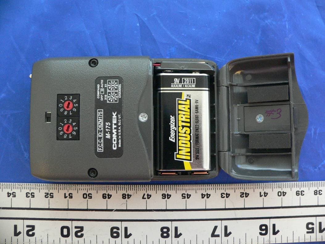
Click to zoom
Application Details
- Equipment Class
- TNT - Licensed Non-Broadcast Transmitter Worn on Body
- Date of Grant
- Sep 11, 2007
- Application Purpose
- Original Equipment
- Date of Application
- Sep 11, 2007
- Equipment Note
- Personal body-worn communication transmitter
- Frequency Range
- 72.02000000 - 75.98000000
- Country
- United States
Documents & Files
Document Text
Text extracted from the exhibit documents filed with the FCC. Open a document above to read the original.
Users Manual
M-175 OPERATOR’S MANUAL (PRELIMINARY) 357 West 2700 South • Salt Lake City, Utah 84115 • Phone: (800) 496-3463 • Fax: (801) 484-6906 • http://www.comtek.com M-175 Personal Communication Transmitter © 2007 COMTEK ® All rights reserved. Printed in the U.S.A. 0107M175 TABLE OF CONTENTS Introduction ........................................................... Setup ............................................................................... Controls .................................................................. Battery Removal / Replacement ...................................... Battery Charging ...................................................... Auxiliary Audio Input Operation ................................... Snap-On Belt Clip ................................................. Frequency Selection .............................................. Frequency Information ......................................... Optional Accessories ............................................ Specifications ......................................................... Warranty and Service .................................................. 1 2 3 4 5 6-7 7 8 9 10 11 12 INTRODUCTION Page 1 T he M-175 transmitter offers the ultimate performance and versatility for applications where one-way personal communication is required. This compact, personal transmitter is ideal for instructors and presenters who must communicate with persons some distance away or in a noisy environment. The M-175 incorporates the latest digital and analog technologies to produce low residual noise, wide dynamic range, and extended frequency response rendering the most natural sound possible from a personal communications system. The audio processing circuit produces full fidelity frequency response from 100 Hz to 10 kHz in the companded or non-companded mode to accommodate a greater variety of receivers. Operating under F.C.C. Regulation Part 90 allows a greater transmission range and reliability than is customary with 72-76 MHz systems. M-175 Personal Communication Transmitter Setup a. Check to ensure that the M-175 transmitter’s radio frequency channel is the same as the associated COMTEK receiver ’s channel. (Channels are indicated by the rotary channel selector switches on the back of the transmitter. See page 8.) b. Open the battery door cover on the transmitter (see page 4) and insert a new nine volt alkaline battery (Eveready E522 or equivalent). This type of battery will offer up to 16 hours of operation. Replace the battery before every use if the demand for fail-safe operation outweighs battery cost. The use of carbon batteries is not recommended. NOTE: If a rechargeable battery is to be used, ensure that it has been allowed to charge at least twelve hours to bring it to full charge (see page 5 for battery charger instructions). c. Connect the microphone to the transmitter by inserting the microphone plug into the receptacle on the top of the transmitter. The transmitter is operating when the transmitter power switch is turned on and the battery status/on indicator illuminates. NOTE: The 48-inch microphone cord also functions as part of the transmitter’s antenna system. For optimum performance, this cord should be fully extended. Coiling or bunching the microphone cord may reduce the range of the transmitter. The transmitter should be carried by the snap-on belt clip (included) or in a pocket or belt-clip pouch. d. In a situation where an extremely loud voice or a very soft voice is used, it is necessary to adjust the audio input gain control while observing the audio “voice” level modulation indicator. A full bright LED indicates full audio compression at 100% modulation. For best performance, the audio input gain should be adjusted for some low level LED luminescence during normal audio levels with occasional full bright peaks indicating 100% modulation. M-175 SETUP Page 2 Page 3 M-175 CONTROLS n COMPAND AUTO / OFF SWITCH: This switch overrides the automatic selection of the companded channels to non-companded operation. o CHANNEL SWITCHES: These rotary switches are used to set the transmitter to the desired operating frequency. (See page 9 and 10 for frequency selection chart.) p BATTERY COMPARTMENT: The battery compartment features a hinged battery cover and an alignment system that ensures proper battery polarity. Battery installation and removal is facilitated by simply manipulating the bottom of the battery. q AUXILIARY AUDIO INPUT JACK: Allows transmitter to use line level, earphone level, or fixed AUX as an audio source. r AUDIO “VOICE” MODULATION INDICATOR: This indicator is used in making adjustment with the Audio Input Gain Control. s MIC / ANTENNA JACK: This jack accepts an electret type microphone having a 48” long cord with a micro-mini 2.5mm mono plug. The microphone cord functions as part of the transmitter’s antenna system and must be in place for auxiliary audio input operation. If microphone function is not necessary, the optional microphone switch should not be on for this operation. t POWER / BATTERY STATUS INDICATOR: This LED indicator will illuminate continuously when the unit is on, indicating normal operation. When the battery voltage drops below 6 volts, the LED will flash rapidly, indicating that a new battery is needed. u OPTIONAL MIC SWITCH: This switch turns off the microphone without turning off the transmitter carrier. v AUDIO INPUT GAIN CONTROL: This is a microphone and AUX level input gain control. This control is used with the “Voice” modulation indicator. w ON / OFF SWITCH: This switch turns the transmitter on and off. Page 4 Low Battery Indicator The LED on the top of the transmitter indicates the status of the battery as well as indicating that the unit is turned on. When the transmitter is turned on, the LED illuminates. If the battery is low, the green LED will blink rapidly to warn you that the battery will soon be dead. Replace a low battery immediately. M-175 BATTERY REMOVAL / REPLA…
Text truncated - open the document above for the full version.
External Photos
EXHIBIT C - EUT PHOTOGRAPHS EUT- Top View EUT- front View EUT- back Side View EUT – back Side View showing battery compartment EUT – back Side View showing battery compartment without battery Microphone and antenna –top View
Internal Photos
EXHIBIT C - EUT PHOTOGRAPHS EUT – chassis off view EUT –board 1 component side view EUT –board 1 solder side view EUT –board 2 component side view EUT –board 2 solder side view
Test Report
Note: This test report is for the customer shown above and their specific product only. It may not be duplicated or used in part without prior written consent from Bay Area Compliance Laboratories Corp. This report must not be used by the customer to claim product certification, approval, or endorsement by NVLAP, NIST, or any agency of the Federal Government ) FCC PART 90 TYPE APPROVALS MEASUREMENT AND TEST REPORT For Comtek Communications Technology, Inc. 357 West 2700 South Salt Lake City, UT 84115, USA FCC ID: C6ZM175 This Report Concerns: Original Report Product type: Person Communication Transmitter Test Engineer: Oscar Au Report Number: R0708153 Report Date: 2007-08-30 Reviewed By: James Ma, Test Engineer Prepared By: (12) Bay Area Compliance Laboratories Corp. 1274 Anvilwood Ave Sunnyvale, CA 94085, U.S.A. Tel: (408) 732-9162 Fax: (408) 732 9164 www.baclcorp.com FCC ID: C6ZM175 Report No.: R0708153-90 Page 2 of 34 FCC Part90 Report TABLE OF CONTENTS GENERAL INFORMATION.......................................................................................................................................4 PRODUCT DESCRIPTION FOR EQUIPMENT UNDER TEST (EUT) .....................................................................................4 MECHANICAL DESCRIPTION.........................................................................................................................................4 EUT PHOTO.................................................................................................................................................................4 OBJECTIVE...................................................................................................................................................................5 RELATED SUBMITTAL(S)/GRANT(S).............................................................................................................................5 TEST METHODOLOGY..................................................................................................................................................5 TEST FACILITY.............................................................................................................................................................5 SYSTEM TEST CONFIGURATION ..........................................................................................................................6 JUSTIFICATION.............................................................................................................................................................6 EQUIPMENT MODIFICATIONS.......................................................................................................................................6 POWER SUPPLY AND LINE FILTERS..............................................................................................................................6 RADIATED EMISSION TEST SETUP BLOCK DIAGRAM...................................................................................................6 SUMMARY OF TEST RESULTS ...............................................................................................................................7 §1.1310 & §2.1093 - RF EXPOSURE...........................................................................................................................8 APPLICABLE STANDARD..............................................................................................................................................8 §2.1046, and §90.205 - RF Output Power ....................................................................................................................9 APPLICABLE STANDARD..............................................................................................................................................9 TEST PROCEDURE........................................................................................................................................................9 ENVIRONMENTAL CONDITIONS....................................................................................................................................9 TEST EQUIPMENT LIST AND DETAILS...........................................................................................................................9 TEST RESULT.............................................................................................................................................................10 §2.1047, and §90.207 - MODULATION CHARACTERISTIC ...............................................................................13 APPLICABLE STANDARD............................................................................................................................................13 TEST PROCEDURE......................................................................................................................................................13 ENVIRONMENTAL CONDITIONS..................................................................................................................................13 TEST EQUIPMENT LIST AND DETAILS.........................................................................................................................13 TEST RESULT.............................................................................................................................................................13 §2.1049 and § 90.209(b) (5)/210 (b) – OCCUPIED BANDWIDTH, EMISSION MASKS & EMISSION LIMITATION..............................................................................................................................................................15 APPLICABLE STANDARD............................................................................................................................................15 TEST PROCEDURE.......................................................................................................................................…
Text truncated - open the document above for the full version.
Test Setup Photos
EXHIBIT B - TEST SETUP PHOTOGRAPHS Radiated Emission – Front View Radiated Emission – Rear View
Contact Information
Applicant
Ralph Belgique(President)
Test Firm
Bay Area Compliance LaboratoryJohn Chan
Technical Specifications
| # | Rule Parts | Frequency Range | Power Output | Emission | Tolerance |
|---|---|---|---|---|---|
| 1 | 90 | 72.02 MHz - 75.98 MHz | 45.50 mW | 19K4F3E | 50.0000000000 ppm |
Other Applications from Comtek Communications Technology Inc

C6ZBST75-216
Jun 22, 2010Mini Base Station Transmitter
Equipment Class
TNB - Licensed Non-Broadcast Station Transmitter
C6ZPR75A
Apr 28, 2004Scanning Receiver in upper 72 MHz to 76 MHz range.
Equipment Class
CSR - Scanning Receiver
C6ZM216
Aug 15, 2001Wireless Microphone Transmitter
Equipment Class
FRT - Part 95 Family Radio Body Worn Transmitter
C6ZBST25-216
Sep 21, 2000Low Power Communications TX
Equipment Class
TNB - Licensed Non-Broadcast Station TransmitterC6ZPR25
Oct 24, 1995CXX - Communications Rcvr for use w/ licensed Tx and CBs
Equipment Class
CXX - Communications Rcvr for use w/ licensed Tx and CBs