C6ZM216Wireless Microphone Transmitter
Comtek Communications Technology Inc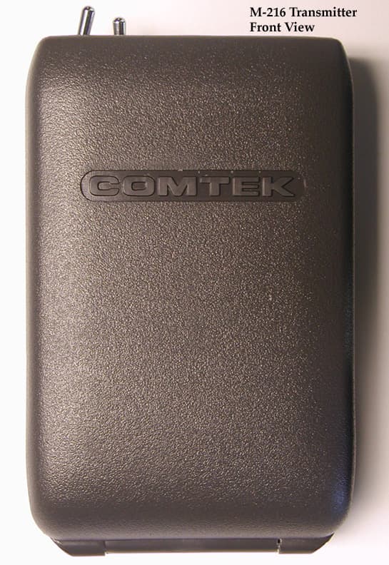
Click to zoom
Application Details
- Equipment Class
- FRT - Part 95 Family Radio Body Worn Transmitter
- Date of Grant
- Aug 15, 2001
- Application Purpose
- Original Equipment
- Date of Application
- Jun 11, 2001
- Equipment Note
- Wireless Microphone Transmitter
- Frequency Range
- 216.00000000 - 217.00000000
- Country
- United States
Documents & Files
Document Text
Text extracted from the exhibit documents filed with the FCC. Open a document above to read the original.
Users Manual
M-216 OPERATOR’S MANUAL 357 West 2700 South • Salt Lake City, Utah 84115 • Phone: (800) 496-3463 • Fax: (801) 484-6906 • http://www.comtek.com M-216WirelessMicrophoneTransmitter INTRODUCTION Page 1 T he M-216 wireless microphone transmitter offers the ultimate performance and versatility for assistivelistening, language interpretation,tour guide presentations, personalcueing, and for other personal remotetransmission situations.The M-216 incorporates the latest digitaland analog technologies to produce lowresidual noise, wide dynamic range,and extended frequency responserendering the most natural soundpossible from a wireless microphone.The transmitter’s microcontrollerautomatically sets the modulation deviation, companding or non- companding audio processing, and the EQ when correspondingchannels are selected. Because of thiscomprehensive feature, thisversatile transmitter can transmiton 19 high fidelity channels and38 standard channels insuringcompatibility with receiversconforming to regulationsregarding Low Power Radio Service(LRPS) transmissions in the 216-217 MHz bandunder Part 95 of the F.C.C. regulations.M-216WirelessMicrophoneTransmitter Setupa. Check to insure that the M-216 transmitter’s radio frequency channel is the same as the associated COMTEK receiver’s channel. (Channels areindicated by the 99 position rotary channel selector switches on the back ofthe transmitter: see page 3.)b. Open the battery door cover on the transmitter (see page 4) and insert a new nine volt alkaline battery (Eveready E522 or equivalent). Thistype of battery will offer up to 40 hours of operation. Replace the battery before every use if the demand for fail-safe operation outweighs battery cost. The use of carbon batteries is not recommended. NOTE: If a rechargeable battery is to be used, insure that it has beenallowed to charge at least twelve hours to bring it to full charge (see page 7 for battery charger instruc tions). c. Connect the microphone to the transmitter by inserting the microphone plug into the receptacle on the top of the transmitter. The transmitter isoperating when the transmitter power switch is turned on and the batterystatus/on indicator illuminates.NOTE: The 36-inch microphone cord also functions as part of thetransmitter’s antenna system. For optimum performance, this cordshould be fully extended. Coiling or bunching the microphonecord may reduce the range of the transmitter. The transmitter should be carried by the snap-on belt clip (in cluded) or in a pocket or belt clip pouch.d. In a situation where an extremely loud voice or a very soft voice is used, it is necessary to adjust the audio input gain control while observing the audio“voice” level modulation indicator. A full bright LED indicates full audiocompression at 100% modulation. For best performance, the audio inputgain should be adjusted for some low level LED luminescence duringnormal audio levels with occasional full bright peaks indicating 100%modulation.M-216 OPERATING INSTRUCTIONS Page 2 Page 3 Frequency Selection (216-217 MHz)The M-216 transmitter can operate on one of 57 available channels between216 MHz and 217 MHz. COMTEK’s channel designations indicate bothstandard narrow-band channels and high fidelity wide-band compandedchannels. Channels 1-40 are narrow-band channels (5 kHz deviation)offering compatibility with other manufacturers’ receivers such as thePhonak MicroEar. Channels 41-60 are high fidelity wide-band compandedchannels (10 kHz deviation) for use with COMTEK transmitters. COMTEKtransmitters automatically transmit the proper modulation when set tochannels 1-40 for narrow-band or 41-60 for wide-band companded chan nels. After you have determined the channel on whichyou are going to operate, position the two rotaryswitches to indicate the channel. The left rotaryswitch is for tens and the right rotary switch is for ones . To select channel 41 (216.0250 MHz), position the left rotary switch to point to 4 (X10),and position the right rotary switch to point to 1 (X1).Refer to frequency charts on pages 9 and 10 for selectable frequencies.Multiple Channel OperationWhen multiple transmitters are broadcasting in the same immediate area (within 100 feet), the RF signals will “mix” together generating additionalsignals. If these product frequencies are too close to a frequency which you areusing, you will experience intermodulation interference. This condition iscommon to all radio receivers to some extent.Simultaneous operation of more than three channels requires frequencycoordination to avoid intermodulation interference, which could result inpoor or unusable performance.To avoid this type of interference, you should select frequencies from one of thestandard groups (see frequency group charts on page 10), or use COMTEK’sfrequency selection software (www.comtek.com/software.htm) to determine appropriate frequen cies or contact COMTEK to obtain a free copy. M-216 OPERATING INSTRUCTIONS Low Battery IndicatorThe LED on the top of the transmitterindicates the status of the battery aswell as indicating that the unit is turnedon. When turned on, the LED illuminates.If the battery is low the green LED willblink rapidly to warn you that the batterywill soon be dead. Replace a low batteryimmediately.Battery Removal / ReplacementM-216 OPERATING INSTRUCTIONS Page 4 Pull back battery door latch and allow battery cover door to spring open. To remove battery, simply manipulate the bottom of battery out of the compart ment and remove. To insert battery, facebattery with negative terminalin line with large hole in batterycompartment, press battery intocompartment and close battery door untilit snaps shut. Note: It is not possible to putbattery in backwards. Battery indicator LED Page 5 M-216 OPERATING INSTRUCTIONSAuxiliary Audio Input OperationThe M-216 transmitter may transmit from avariety of audio sources such as tape and C.D.players, TV and VCR’s, or any audio devicehaving an auxiliary or line level audio output.Th…
Text truncated - open the document above for the full version.
Attestation Statements
This transmitter is authorized by rule under the Low Power Radio Service (47 C.F.R. Part 95) and must not cause harmful interference to TV reception or United States Navy SPASUR installations. You do not need an FCC license to operate this transmitter. This transmitter may only be used to provide: auditory assistance to persons with disabilities, persons who require language translation, or persons in educational settings; health care services to the ill; law enforcement tracking services under agreement with a law enforcement agency; or automated maritime telecommunications system (AMTS) network control communications. Two-way voice communications and all other types of uses not mentioned above are expressly prohibited.
Cover Letter(s)
FCC ID: C6ZM216 MFA p0160002, d0160007 Sincerely yours, Morton Flom, P. Eng.
Test Report
FCC ID: C6ZM216 MFA p0160002, d0160006 Date: June 12, 2001 Federal Communications Commission VIA ELECTRONIC FILING Attention: Authorization & Evaluation Division Applicant: Comtek Communications Technology, Inc. Equipment: M-216 FCC ID: C6ZM216 FCC Rules: 95G, 95.629(b) and (c), Confidentiality Gentlemen: On behalf of the Applicant, enclosed please find Application Form 731, Engineering Test Report and all pertinent documentation, the whole for approval of the referenced equipment as shown. Filing fees are attached. Please note that except for the Radiated tests, all testing has been conducted by the Applicant. We trust the same is in order. Should you need any further information, kindly contact the writer who is authorized to act as agent. Sincerely yours, Morton Flom, P. Eng. enclosure(s) cc: Applicant MF/cvr FCC ID: C6ZM216 MFA p0160002, d0160006 LIST OF EXHIBITS (FCCCERTIFICATION(TRANSMITTERS) - REVISED 9/28/98) APPLICANT: Comtek Communications Technology, Inc. FCC ID: C6ZM216 BY APPLICANT: 1. LETTER OF AUTHORIZATION 2. IDENTIFICATION DRAWINGS, 2.1033(c)(11) LABEL LOCATION OF LABEL COMPLIANCE STATEMENT LOCATION OF COMPLIANCE STATEMENT 3. PHOTOGRAPHS, 2.1033(c)(12) 4. DOCUMENTATION: 2.1033(c) (3) USER MANUAL (9) TUNE UP INFO (10) SCHEMATIC DIAGRAM (10) CIRCUIT DESCRIPTION BLOCK DIAGRAM PARTS LIST ACTIVE DEVICES 5. PART 95.1015(a) ATTESTATION BY M.F.A. INC. A. TESTIMONIAL & STATEMENT OF CERTIFICATION B. STATEMENT OF QUALIFICATIONS FCC ID: C6ZM216 MFA p0160002, d0160006 TRANSMITTER CERTIFICATION of FCC ID: C6ZM216 MODEL: M-216 to FEDERAL COMMUNICATIONS COMMISSION Rule Part(s) 95G, 95.629(b) and (c), Confidentiality DATE OF REPORT: June 12, 2001 ON THE BEHALF OF THE APPLICANT: Comtek Communications Technology, Inc. AT THE REQUEST OF : P.O. F0061 Comtek Communications Technology, Inc. 357 W. 2700 South Salt Lake City, UTAH 84115 Attention of: Ralph Belgique, President (801) 446-3463, FAX: 484-6906 SUPERVISED BY: Morton Flom, P. Eng. FCC ID: C6ZM216 MFA p0160002, d0160006 THE APPLICANT HAS BEEN CAUTIONED AS TO THE FOLLOWING: 15.21 INFORMATION TO USER. The users manual or instruction manual for an intentional radiator shall caution the user that changes or modifications not expressly approved by the party responsible for compliance could void the user's authority to operate the equipment. 15.27(a) SPECIAL ACCESSORIES. Equipment marketed to a consumer must be capable of complying with the necessary regulations in the configuration in which the equipment is marketed. Where special accessories, such as shielded cables and/or special connectors are required to enable an unintentional or intentional radiator to comply with the emission limits in this part, the equipment must be marketed with, i.e. shipped and sold with, those special accessories. However, in lieu of shipping or packaging the special accessories with the unintentional or intentional radiator, the responsible party may employ other methods of ensuring that the special accessories are provided to the consumer, without additional charge. Information detailing any alternative method used to supply the special accessories for a grant of equipment authorization or retained in the verification records, as appropriate. The party responsible for the equipment, as detailed in § 2.909 of this chapter, shall ensure that these special accessories are provided with the equipment. The instruction manual for such devices shall include appropriate instructions on the first page of text concerned with the installation of the device that these special accessories must be used with the device. It is the responsibility of the user to use the needed special accessories supplied with the equipment. FCC ID: C6ZM216 MFA p0160002, d0160006 TABLE OF CONTENTS RULEDESCRIPTIONPAGE . Test Report 1 2.1033(c) General Information Required 2 2.1033(c) General Information Required 3 2.1033(c)(14) Rule Summary 5 . Standard Test Conditions and Engineering Practices 6 2.1046(a) Carrier Output Power (Radiated) 7 2.1053(a) Field Strength of Spurious Radiation 9 2.1049(c)(1) Emission Masks (Occupied Bandwidth) 15 2.1047(a) Audio Frequency Response 17 2.1055(a)(1) Frequency Stability (Temperature Variation) 18 2.1055(b)(1) Frequency Stability (Voltage Variation) 19 2.202(g) Necessary Bandwidth and Emission Bandwidth 21 FCC ID: C6ZM216 MFA p0160002, d0160006 PAGE NO.1of22. Required information per ISO/IEC Guide 25-1990, paragraph 13.2: a) TEST REPORT b) Laboratory: (FCC: 31040/SIT) (Canada: IC 2044) M. Flom Associates, Inc. 3356 N. San Marcos Place, Suite 107 Chandler, AZ 85225 c) Report Number: d0160006 d) Client: Comtek Communications Technology, Inc. 357 W. 2700 South Salt Lake City, UTAH 84115 e) Identification: M-216 FCC ID: C6ZM216 Description: Wireless Microphone Transmitter f) EUT Condition: Not required unless specified in individual tests. g) Report Date: June 12, 2001 EUT Received: June 6, 2001 h, j, k): As indicated in individual tests. i) Sampling method: No sampling procedure used. l) Uncertainty: In accordance with MFA internal quality manual. m) Supervised by: Morton Flom, P. Eng. n) Results: The results presented in this report relate only to the item tested. o) Reproduction: This report must not be reproduced, except in full, without written permission from this laboratory. FCC ID: C6ZM216 MFA p0160002, d0160006 PAGE NO.2of22. GENERAL INFORMATION REQUIRED FOR CERTIFICATION Sub-part 2.948: (a)(b) DESCRIPTION OF MEASUREMENT FACILITIES: FILE: 31040/511 A description of the measurement facilities was filed with the Commission and was found to be in compliance with the requirements of Section 2.948, by letter dated March 3, 1997. All pertinent changes will be reported to the Commission by up-date prior to March 2000. (b)(4): SUPPORTING STRUCTURES: SKETCH – ATTACHED EXHIBITS (b)(5)(6): TEST INSTRUMENTATION: LIST – SEE EXHIBITS 2.925: IDENTIFICATION OF AN AUTHORIZED DEVICE: DRAWING – SEE EXHIBITS LOCATION OF LABEL – SEE PHOTOS (c)(1): NAME AND ADDRESS OF APPLIC…
Text truncated - open the document above for the full version.
Contact Information
Applicant
Ralph Belgique(President)
Technical Contact
M. Flom Associates, IncMorton Flom
[email protected]480 926 3100
3356 N. San Marcos Pl., Suite 107 · Chandler, Arizona · United States
Non-Technical Contact
M. Flom Associates, Inc.Morton Flom
[email protected]480 926 3100
Test Firm
M. Flom Associates, Inc.Morton Flom
Technical Specifications
| # | Rule Parts | Frequency Range | Power Output | Emission | Tolerance |
|---|---|---|---|---|---|
| 2 | 95G | 216 MHz - 217 MHz | 10.00 mW | 11K0F3E | 50 ppm |
Other Applications from Comtek Communications Technology Inc

C6ZBST75-216
Jun 22, 2010Mini Base Station Transmitter
Equipment Class
TNB - Licensed Non-Broadcast Station Transmitter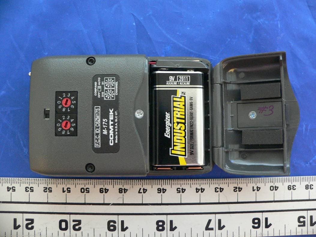
C6ZM175
Sep 11, 2007Personal body-worn communication transmitter
Equipment Class
TNT - Licensed Non-Broadcast Transmitter Worn on Body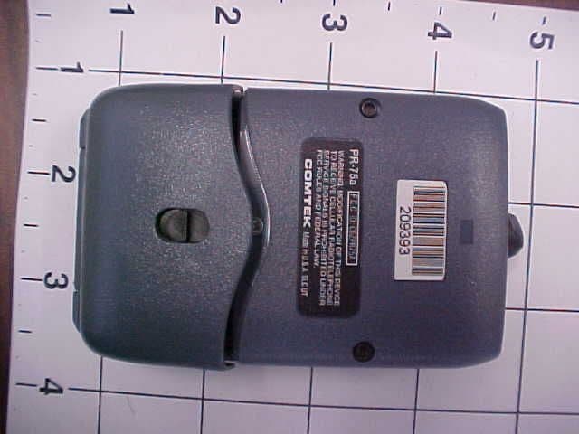
C6ZPR75A
Apr 28, 2004Scanning Receiver in upper 72 MHz to 76 MHz range.
Equipment Class
CSR - Scanning Receiver
C6ZBST25-216
Sep 21, 2000Low Power Communications TX
Equipment Class
TNB - Licensed Non-Broadcast Station TransmitterC6ZPR25
Oct 24, 1995CXX - Communications Rcvr for use w/ licensed Tx and CBs
Equipment Class
CXX - Communications Rcvr for use w/ licensed Tx and CBs