C6ZPR75AScanning Receiver in upper 72 MHz to 76 MHz range.
Comtek Communications Technology Inc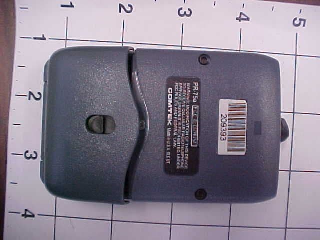
Click to zoom
Application Details
- Equipment Class
- CSR - Scanning Receiver
- Date of Grant
- Apr 28, 2004
- Application Purpose
- Original Equipment
- Date of Application
- Feb 29, 2004
- Equipment Note
- Scanning Receiver in upper 72 MHz to 76 MHz range.
- Frequency Range
- 72.00000000 - 76.00000000
- Country
- United States
Documents & Files
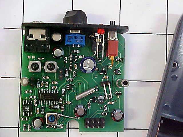
Document Text
Text extracted from the exhibit documents filed with the FCC. Open a document above to read the original.
Users Manual
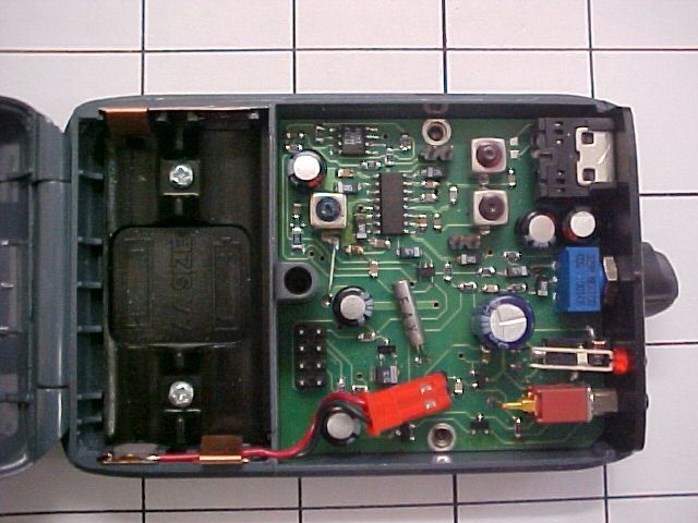
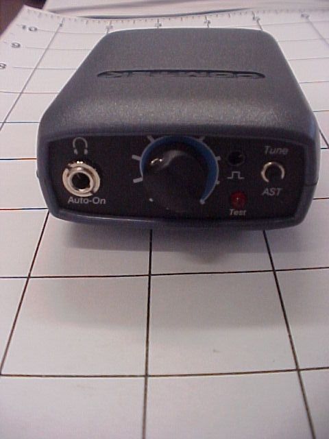
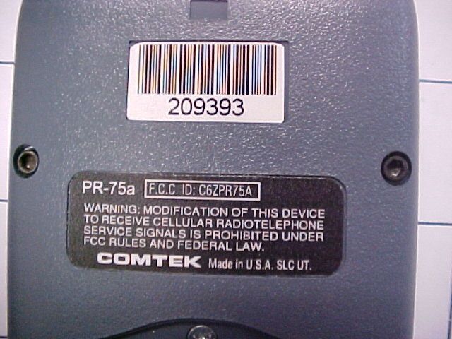
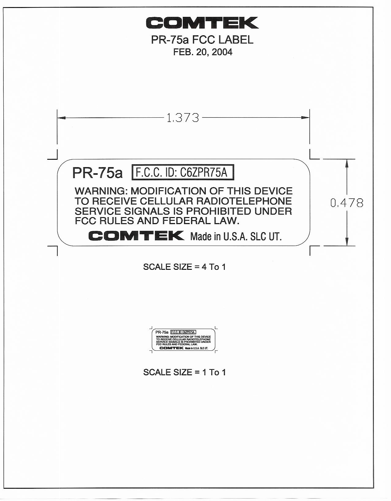
OPERATOR’S MANUAL 357 West 2700 South • Salt Lake City, Utah 84115 • Phone: (800) 496-3463 • Fax: (801) 484-6906 • http://www.comtek.com PR-75a AutoSmart-Tuning TM Assistive Listening Receiver TABLE OF CONTENTS Introduction .......................................................... Controls and Indicators .................................. Setup and Operation ..................................................... Optional Accessories ........................................ Frequency Information ..................................... Battery Information ............................................... Belt Clip Installation and Removal ........................ Specifications .................................................... Warranty and Service ....................................... © 2004 COMTEK ® All rights reserved. Print Release Date 02-20-2004 1 2 3-4 5 6-7 8-9 10 11 12 WARNING: MODIFICATION OF THIS DEVICE TO RECEIVE CELLULAR RADIOTELEPHONE SERVICE SIGNALS IS PROHIBITED UNDER FCC RULES AND FEDERAL LAW. INTRODUCTION Page 1 T he PR-75a personal receiver is the newest generation of user-friendly, high fidelity monitor receivers for auditory assistance and other personal communication applications. When turned on, this unique receiver will automatically tune itself to the closest transmitter. If other transmissions need to be monitored, a manual, AutoSmart-Tuning TM (AST) control will cause the receiver to seek any on-channel group frequency transmission in the 72-76 MHz band. PR-75a AutoSmart-Tuning TM Assistive Listening Receiver PR-75a CONTROLS AND INDICATORS Page 2 PR-75a Controls ! BATTERY COMPARTMENT: The battery compartment features a hinged battery cover and a polarity protection design to ensure that only proper battery polarity can occur. " AUDIO OUTPUT JACK: This stereo/mono audio output jack accommodates any low impedance headphone; also functions as automatic on/off power switch when headphone is plugged in and as rechargeable battery charging access. # VOLUME CONTROL: This control has 50 dB of range to adjust the audio output for a comfortable listening level (clockwise for maximum level). $ POWER / RECEIVER STATUS INDICATOR: LED indicator will display these four functions: a. Fast blinking ----- Seeking channel b. Continuous ------- Receiving signal c. Steady slow flash -------- No signal d. Rapid flash ------ Low battery Additionally there is an audible beeping to indicate a low battery. % AutoSmart-Tuning TM PUSH BUTTON: This one-button tuning control (AST) allows the receiver to seek other channels within the frequency group to which it is tuned. & DATA I/O PORT: For channel programming of specialty channel sequencing. Setup a. Open the battery door on the receiver (see page 8) and insert two 1.5 V AA alkaline batteries (Eveready E91 or equivalent). This type of battery will offer up to 100 hours of operation. If a rechargeable battery is to be used, ensure that it has been allowed to charge at least twelve hours to bring it to full charge (see page 9 for battery charger instructions). Replace the battery before every use if the demand for fail-safe operation outweighs battery cost. The use of carbon batteries is not recommended. b. Ensure that there is a signal on the air on a channel from A-J (see frequency chart page 6). The PR-75a receiver must be within 150 feet of the transmitter for best reception. c. Plugging the earphone into the “Auto-On” output jack on the top of the PR-75a receiver will automatically turn on the receiver and initiate the AutoSmart-Tuning TM process. (The LED will blink very rapidly during this process.) The receiver will then tune itself to the closest on-air transmitter in its vicinity. Based on the first channel found, the receiver will then determine the channel group to which it belongs for multiple channel operation. (The LED will illuminate continuously when a signal is being received.) Pushing the AutoSmart-Tuning TM button (AST) will cause the receiver to seek another compatible channel being transmitted in the frequency group being used. NOTE: The headphone cord also functions as part of the receiver’s antenna system. For optimum performance, this cord should be fully extended. Coiling or bunching the headphone cord may reduce the range of the receiver. Also, coil-cord type headphone cords are not recommended. The receiver should be carried by the snap-on belt clip (included) or in a pocket or belt-clip pouch. d. Set the audio output level control to a comfortable listening volume. This control is turned clockwise for maximum output level. PR-75a SETUP AND OPERATION Page 3 Page 4 PR-75a SETUP AND OPERATION Monitoring Capabilities Because each monitoring application requires a different headphone or transducer to best satisfy each listening need, the PR-75a can source a strong audio signal (200 mW) to either stereo or mono headphones with an impedance as low as 16 ohm. A hearing aid type button receiver may be used with an impedance as high as 2k ohm and still produce a strong audio signal. The PR-75a is ideal for use with the COMTEK NTC-102 neckloop transductor and wireless IR-230 miniature universal-fit ear canal inductor receiver or with hearing aids having a “T” switch. Can be used with consumer or professional headphones. Can be used with hearing aid button receivers for assistive listening or acoustic ear tube for IFB application. Can be used to drive neckloop for use with IR-230 inductor receiver or hearing aids. Page 5 PR-75a OPTIONAL ACCESSORIES Optional Accessories 1. NBC 3-1 3 volt 12 hour battery charger 2. NH 1600 Rechargeable Ni-MH battery (1.2 volt 1600 mAh) 3. P-1 Universal pouch 4. BC-216 Snap-on belt clip (supplied with PR-75a) 5. ET-4 SM-N Button receiver with acoustic ear tube 6. LS-3 High efficiency headphones 7. SM-N Button receiver earphone assembly 8. NTC-102 Neckloop transductor (for use with hearing aids or IR230) 9. NBC 9-3-12 Digital 12 station fast charger 10. FP-75 Channel programmer PR-75a FREQUENCY I…
Text truncated - open the document above for the full version.
Cover Letter(s)
Date: March 1, 2004 FEDERAL COMMUNICATIONS COMMISSION Equipment Approval Services P.O. Box 358315 Pittsburgh, PA 15251-5315 Attn: New Applications Subject: FCC ID # C6ZPR75A Re: COMTEK PR-75a Receiver Application for Equipment Authorization-Certification. Model: PR-75a To Whom It May Concern, We are acting on behalf of COMTEK, to test and certify their PR-75a Scanning Receiver. We are also filing the FCC application for COMTEK. Should any questions arise regarding this matter, kindly contact the undersigned. Sincerely, DNB Engineering, Inc. Clay Allred Lab Manager DNB Engineering, Inc CA:jw
Test Report
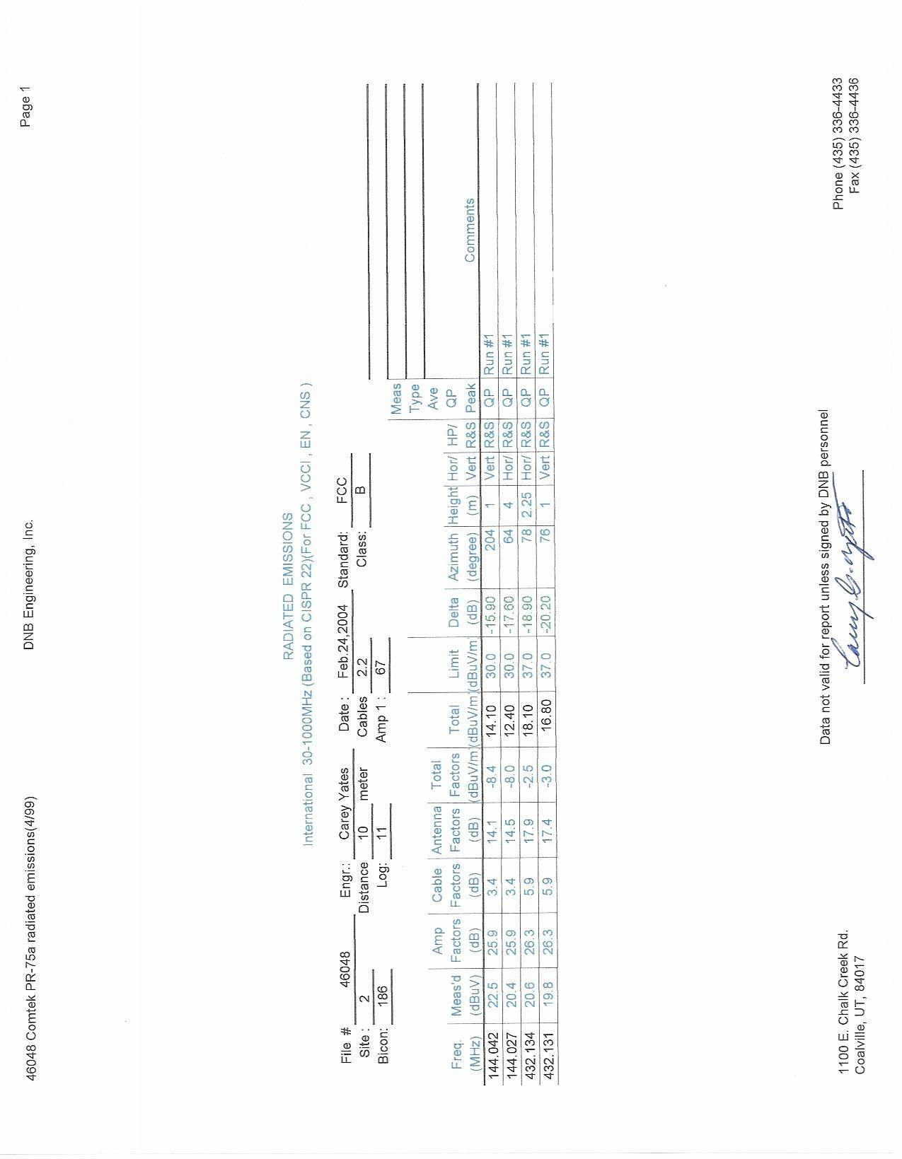
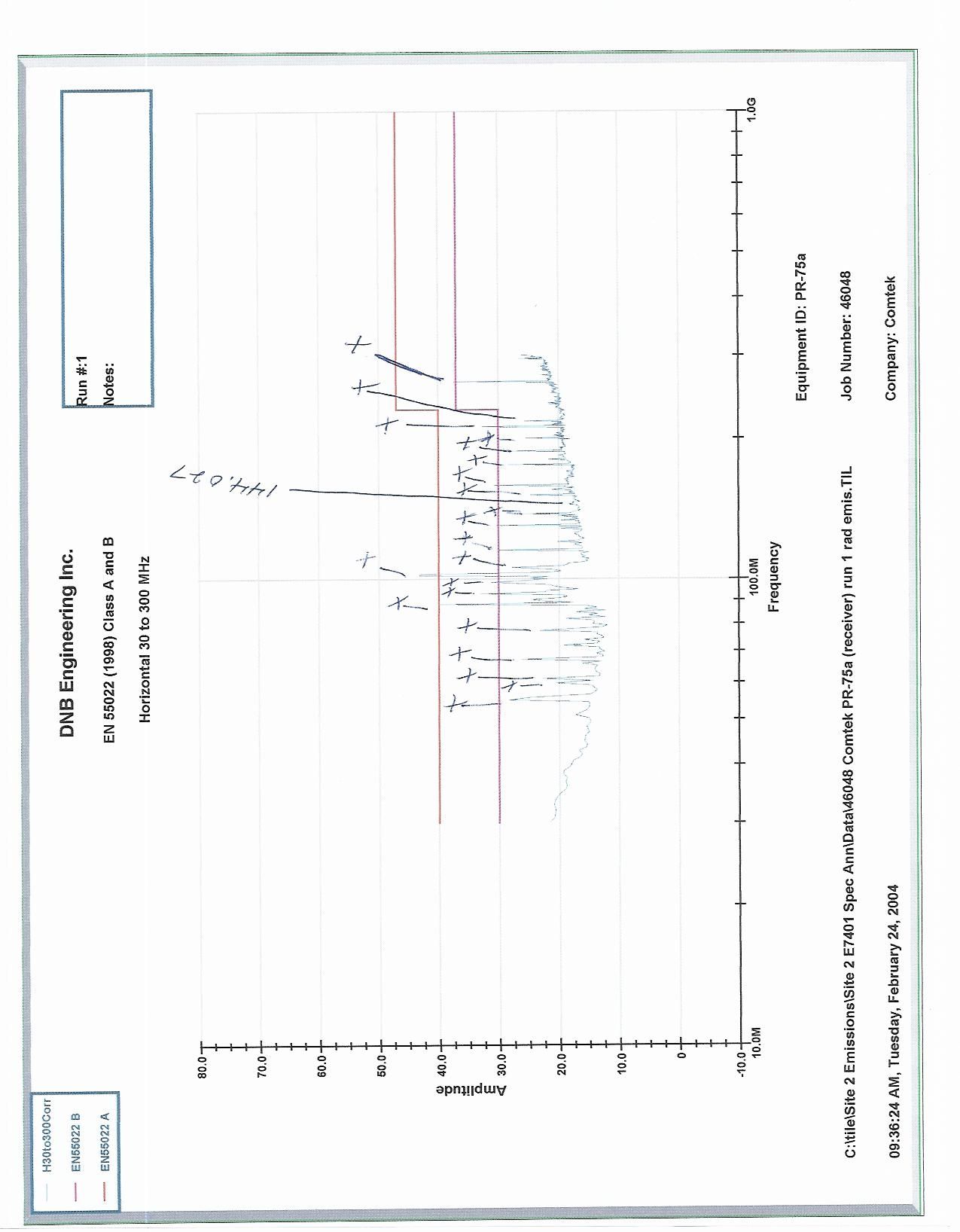
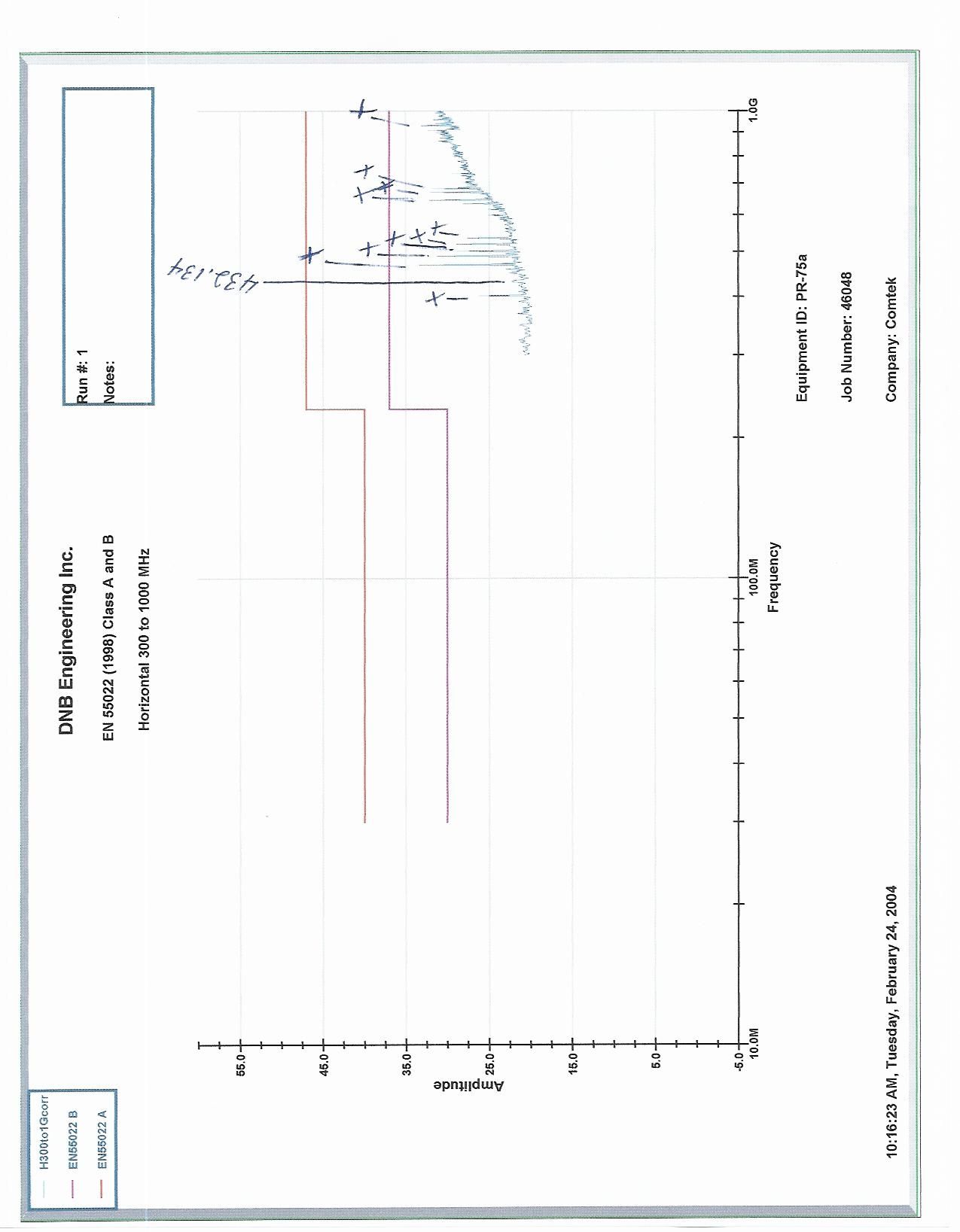
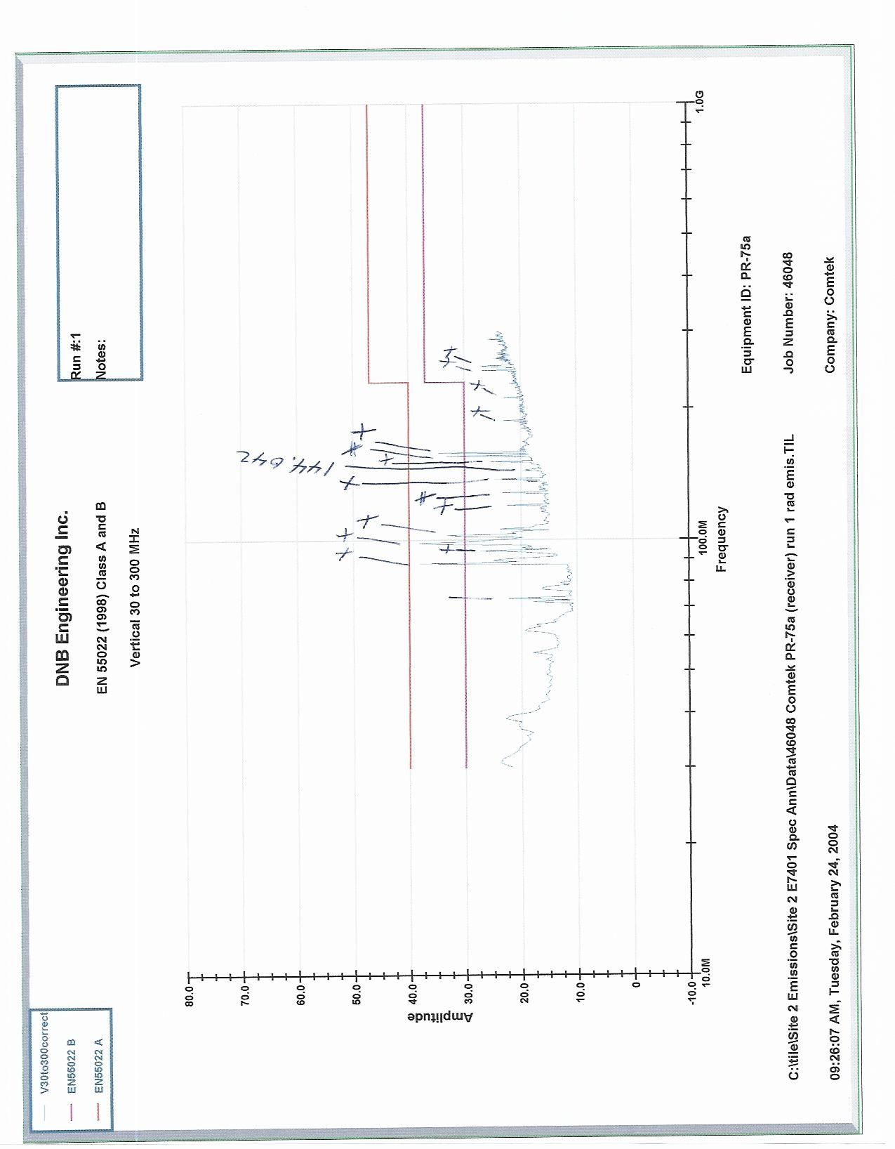
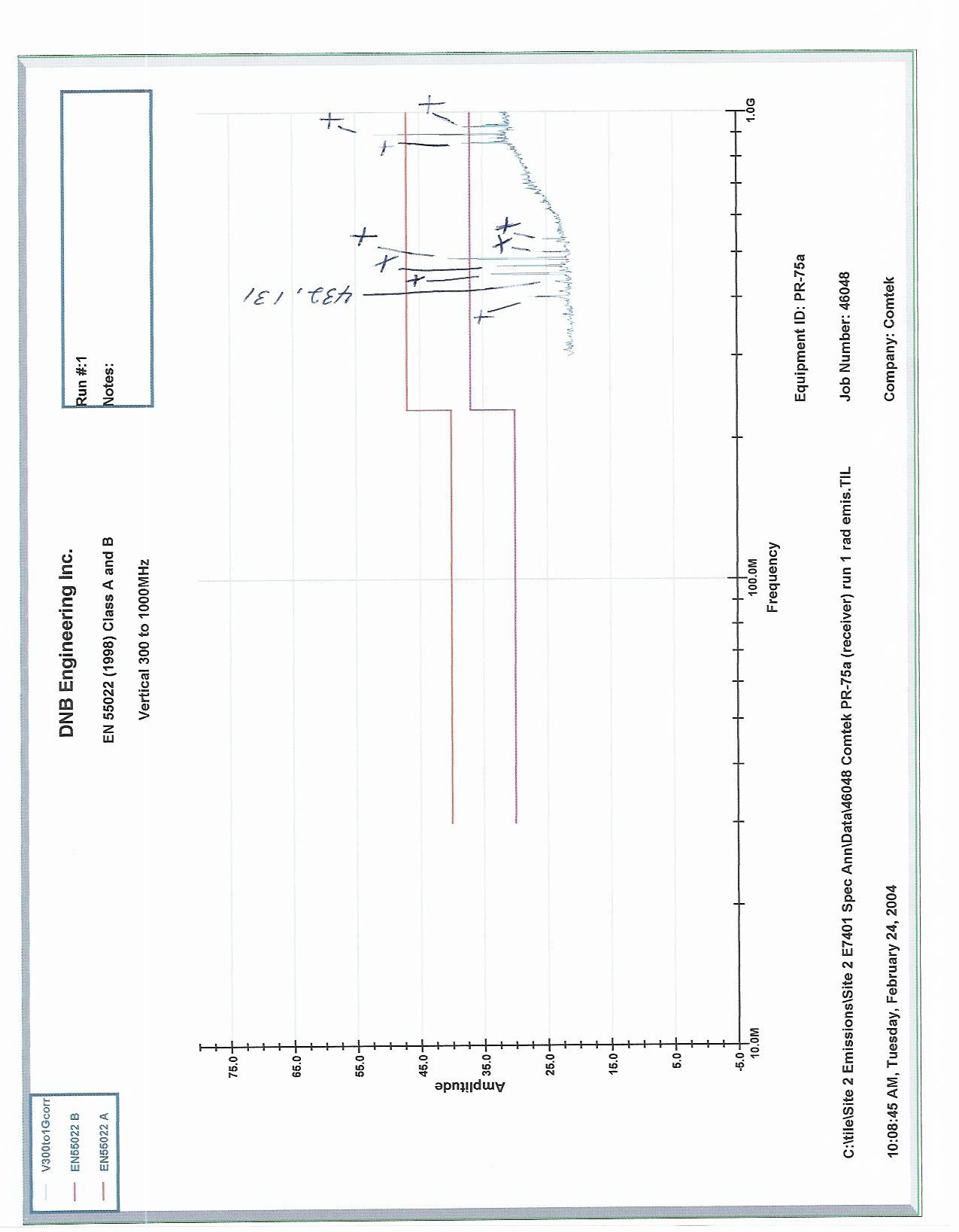
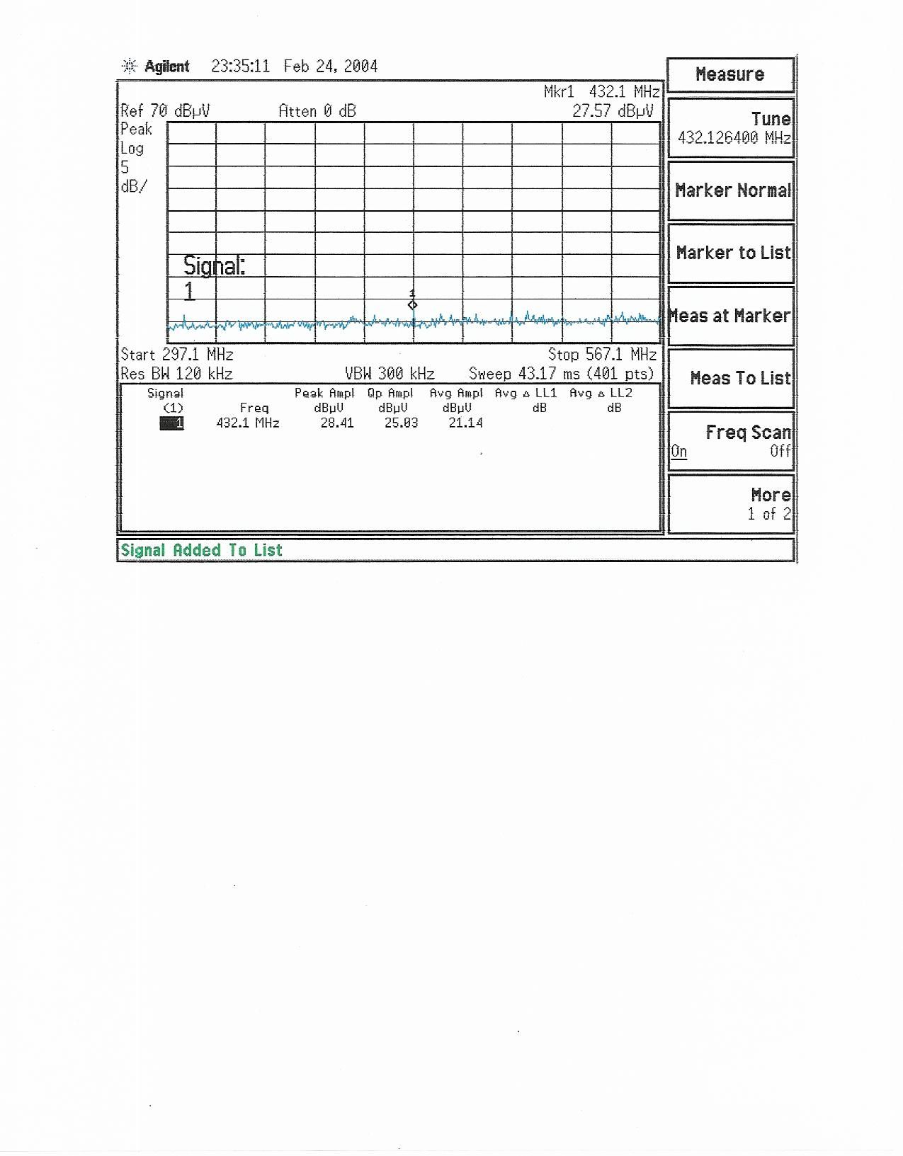
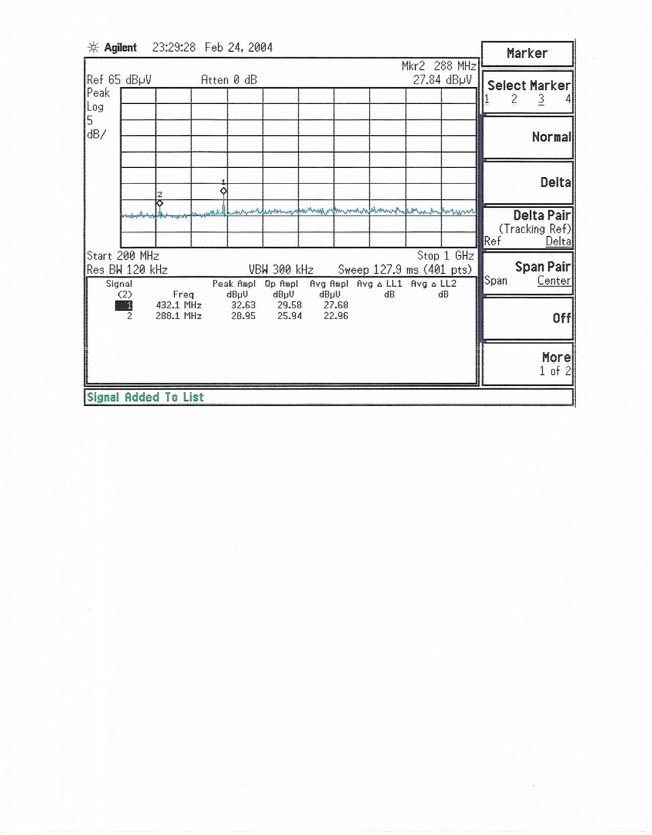
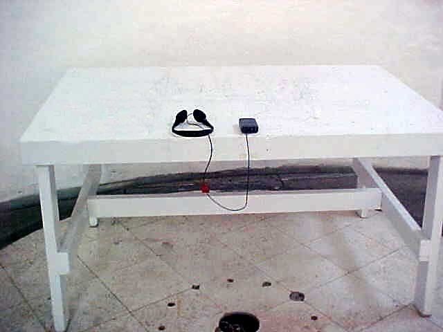
FCC ID: C6ZPR75A DATE: 3/1/2004 REPORT #46048FCC 1 Per 47 CFR, Part 15 Subpart B EUT: PR-75a FCC ID # C6ZPR75A PREPARED FOR APPLICANT: COMTEK 357 West 2700 South Salt Lake City, Utah 84115 REPORT # 46048FCC Test Completion Date: February 24, 2004 Prepared By: DNB ENGINEERING, INC. 1100 East Chalk Creek Rd. Coalville, Utah 84017 Tel: 1(435) 336-4433 APPLICATION FOR CERTIFICATION OF A CLASS B DEVICE (Scanning Receiver) ELA #116 NVLAP Lab Code 200634-0 FCC ID: C6ZPR75A DATE: 3/1/2004 REPORT #46048FCC 2 EXECUTIVE SUMMARY The purpose of this series of tests was to demonstrate the Electromagnetic Compatibility (EMC) characteristics of the PR-75a, the following tests were performed: REQUIREMENTS STATUS COMPLIANT Yes/No/NA 47 CFR Part 15, EN 55022 (1998) ITE Emissions Yes Radiated Emissions Class B Yes Compliance to EN 55022 is acceptable for demonstration of compliance to FCC Part 15 Subpart B, reference CFR 47 15.107(e) and 15.109(g). Signed By: Clay Allred Lab Manager DNB Engineering Inc. This report shall not be reproduced without the written approval of DNB ENGINEERING, INC. Results contained in this report relate only to the item tested. FCC ID: C6ZPR75A DATE: 3/1/2004 REPORT #46048FCC 3 DOCUMENT HISTORY Revision Letter Number of Pages Page No. of Rev. Description Date 1A 41 Document Release 3/1/2004 FCC ID: C6ZPR75A DATE: 3/1/2004 REPORT #46048FCC 4 TABLE OF CONTENTS 1. INTRODUCTION_______________________________________________________8 1.1 Administrative Data Per 2.1033(a) and 2.911(c)__________________________8 1.1.1 REQUEST FOR CERTIFICATION Per 2.1033(b)1:______________________8 1.2 Related Submittals/Grants___________________________________________8 2. Test Description_______________________________________________________8 2.1 System Configuration Table_________________________________________8 2.2 Equipment Description______________________________________________9 2.3 Circuit Description - per 2.1033(b)4___________________________________10 2.3.1 Mode of Operation_____________________________________________10 2.3.2 Modifications to EUT____________________________________________10 2.3.3 Deviations____________________________________________________10 2.3.4 Receiver’s Incapability to Receive Information________________________11 2.3.5 Test Block Diagram_____________________________________________12 2.4 Photograph of EUT - per 2.1033(b)(7)_________________________________13 2.5 Photograph of EUT - per 2.1033(b)(7)_________________________________14 2.6 Photograph of EUT - per 2.1033(b)(7)_________________________________15 2.7 Photograph of EUT - per 2.1033(b)(7)_________________________________16 3. EMISSIONS FCC part 15_______________________________________________17 3.1 Radiated Emissions Test Setup and Procedure - Per 2.1033(b)(6) Per 2.947(a)17 3.1.1 Spurious Radiation Test Site Per 2.1033(b)6________________________17 3.1.2 Radiated Emissions Compliance Data______________________________20 3.1.3 Climatic Conditions_____________________________________________20 3.1.4 Compliant Statement____________________________________________20 3.1.5 Test Data For Radiated Emissions_________________________________21 3.1.6 Test Data For Radiated Emissions_________________________________22 3.1.7 Test Data For Radiated Emissions_________________________________23 3.1.8 Test Data For Radiated Emissions_________________________________24 3.1.9 Test Data For Radiated Emissions_________________________________25 3.1.10 Photograph of Radiated Test Setup per 2.1033(b)5____________________26 4. Exploratory Emissions________________________________________________27 4.1.1 Test Data For Radiated Emissions (Exploratory Emissions)______________28 4.1.2 Test Data For Radiated Emissions (Exploratory Emissions)______________29 4.1.3 Photograph of Exploratory Emissions per 2.1033(b)5___________________30 5. LABELING REQUIREMENTS - per 2.1033(B)(7)_____________________________31 5.1 Additional Label Required__________________________________________31 FCC ID: C6ZPR75A DATE: 3/1/2004 REPORT #46048FCC 5 5.2 Photograph of Label Placement and Contents__________________________31 5.3 SAMPLE OF LABELING____________________________________________32 6. OWNERS MANUAL____________________________________________________33 7. APPENDIX SECTION________________________________________________34 7.1 APPENDIX B: UNCERTAINTY TOLERANCE____________________________35 7.2 APPENDIX C: TEST SITE CERTIFICATION, CHALK CREEK EMI SITE - per 2.948(a)_________________________________________________________36 7.2.1 Ambient Emissions_____________________________________________36 7.2.2 FCC Certification_______________________________________________37 7.2.3 NVLAP Accreditation____________________________________________38 7.2.4 NVLAP Accreditation____________________________________________39 7.2.5 Nemko Accreditation____________________________________________40 7.3 APPENDIX C:_____________________________________________________41 7.4 APPENDIX D: Equipment Used for Test Data___________________________41 End of Report 46048FCC________________________________________________41 FCC ID: C6ZPR75A DATE: 3/1/2004 REPORT #46048FCC 6 TRANSMITTAL SUMMARY Unit tested: PR-75a FCC ID# C6ZPR75A Specifications: ANSI C63.4 2000 47 CFR, Part 15 Subpart B Purpose of Report: This report was prepared to document the status of the PR-75a with requirements of the regulations listed above. Test Summary The EUT’s compliance status according to the tests performed is as follows. Refer to Section page 2 Executive Summary. FCC ID: C6ZPR75A DATE: 3/1/2004 REPORT #46048FCC 7 CERTIFICATION OF TEST DATA This report, containing emissions test data and evaluations, has been prepared by an independent electromagnetic compatibility laboratory, DNB ENGINEERING, in accordance with the applicable specifications and instructions required per the Introduction. NEMKO and the National Institute of Standards and Technology have evaluated DNB Engineering to do these tests…
Text truncated - open the document above for the full version.
Contact Information
Applicant
Ralph Belgique(President)
Technical Contact
DNB Engineering, IncClay Allred
[email protected]435-336-4433
1100 East Chalk Creek Road · Coalville, Utah · United States
Test Firm
DNB Engineering, Inc.Michael Neis
Technical Specifications
| # | Rule Parts | Frequency Range | Power Output |
|---|---|---|---|
| 1 | 15B | 72 MHz - 76 MHz | - |
Other Applications from Comtek Communications Technology Inc

C6ZBST75-216
Jun 22, 2010Mini Base Station Transmitter
Equipment Class
TNB - Licensed Non-Broadcast Station Transmitter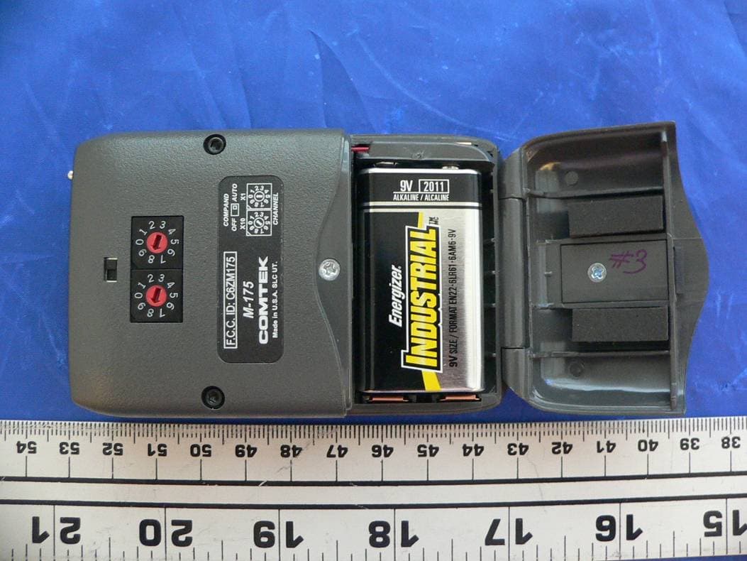
C6ZM175
Sep 11, 2007Personal body-worn communication transmitter
Equipment Class
TNT - Licensed Non-Broadcast Transmitter Worn on Body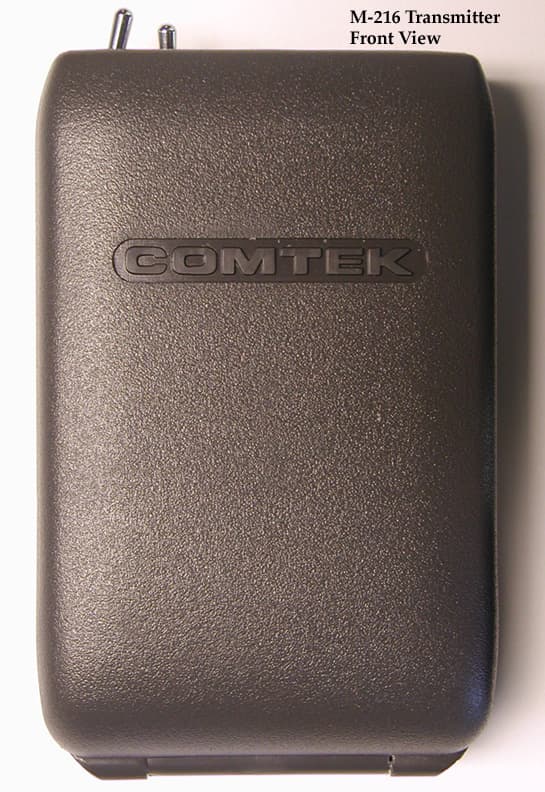
C6ZM216
Aug 15, 2001Wireless Microphone Transmitter
Equipment Class
FRT - Part 95 Family Radio Body Worn Transmitter
C6ZBST25-216
Sep 21, 2000Low Power Communications TX
Equipment Class
TNB - Licensed Non-Broadcast Station TransmitterC6ZPR25
Oct 24, 1995CXX - Communications Rcvr for use w/ licensed Tx and CBs
Equipment Class
CXX - Communications Rcvr for use w/ licensed Tx and CBs