C8LB3060V2Defence Radio for Civil and Military applications
Park Air Systems Limited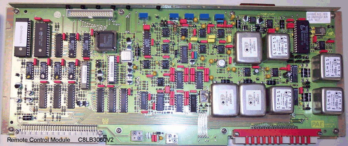
Click to zoom
Application Details
- Equipment Class
- TNB - Licensed Non-Broadcast Station Transmitter
- Date of Grant
- Nov 07, 2002
- Application Purpose
- Original Equipment
- Date of Application
- Jan 10, 2002
- Equipment Note
- Defence Radio for Civil and Military applications
- Frequency Range
- 118.00000000 - 136.97500000
- Company
- Park Air Systems Limited
- Country
- United Kingdom
Documents & Files
Document Text
Text extracted from the exhibit documents filed with the FCC. Open a document above to read the original.
Users Manual
ISSUE 2 Series 3000DV2 Radios User Guide Handbook Title:Series 3000DV2 Radios User Guide Handbook Part Number:31-33000DTR Issue Number:2 Date of IssueJuly 2000 Page ii3000DV2 Radios Handbook Amendment Record Amendments to this handbook, originated by Park Air Electronics, are listed in the following table. Amendment Number DateBrief DetailsPAE Change Note Number Equipment Modification Record Modifications to the 3000DV2 radios are detailed in the following table. Modification Number DateBrief DetailsPAE Change Note Number 1 March '99RF PA capacitors C17, C26, C39, C40 changed. 3590 3000DV2 RadiosPage iii Warnings Warning. Lethal Voltages! Installation involves the connection of lethal voltages. The instructions detailed in this handbook must be carried out only by suitably qualified personnel. Warning. Heavy Item! The 3000DV2 series radios weigh in excess of 25 kg; care must be taken when lifting and handling these units. At least two people must be used to lift the equipment. Warning. Antenna Radiation! Antennas used with 3000DV2 transmitters and transceivers must be installed such that the resultant radiated field strength is below 10 watt per square metre in areas normally accessible to personnel. Warning. Beryllium/Beryllia! The equipment covered by this handbook contains components incorporating the highly toxic material Beryllium and/or its oxide Beryllia. No instructions within this user guide require the removal of the radio's top or bottom covers so users are not exposed to a potential beryllium hazard. If the radio is to be disposed of, users must be aware of current disposal regulations regarding equipment containing Beryllium/Beryllia. Caution Caution. Electrostatic Sensitive Devices! The equipment covered by this handbook contains electrostatic sensitive devices some of which are exposed when the rear panel is hinged down to obtain access to the mains voltage selector (see section 3 page 8 ). Observe handling precautions to avoid static charges which may damage these devices. FEDERAL COMMUNICATIONS COMMISSION (FCC) REGULATIONS q This device complies with Part 15 of the FCC Rules. Operation is subject to the condition that this device does not cause harmful interference. q You are required to obtain a station licence before transmitting from your base station. q This equipment is only licenced for operation on 25 kHz channel spacing in the VHF aeronautical band of 118 MHz to 136.975MHz employing amplitude modulation. q The base station power output must not exceed the output necessary for satisfactory technical operation taking account of local conditions and the area to be covered. q The base station's frequency and parameters should be checked by authorized service personnel before use, and at least yearly thereafter. ------------------------------------------------------------------------------------------------------------------------ Page iv 3000DV2 Radios Contents This handbook is divided into the following sections Section 1General Information Section 2Specification Section 3Installation and Setting-Up Instructions Section 4Operation Section 5Spares Section 6Figures 3000DV2 RadiosPage v General Information Contents Paragraph 1Introduction 4Equipment overview 8Power supplies 10Built-in test facility 12Types of installation 13Control of equipment 16Options 17VHF/UHF guard receiver (option 01) 18Configurable antenna port (option 04) 19Fill gun port (option 05) 20External power amplifier/filter drive (option 06) 21Internal have quick (option 07) 22VHF frequency extension (option 08) 23Maritime band (option 10) 24Internal quick fox module (option 12) 25User maintenance TablePage 1-1Options - Model Applicability5 INTRODUCTION 1This handbook describes the installation and operation of the Park Air Electronics (PAE) series 3000DV2 radios. The series comprises the following models: ❏ 3040V2 UHF transmitter/receiver ❏ 3070V2 VHF transmitter/receiver ❏ 3060V2 VHF/UHF transmitter/receiver ❏ 3140V2 UHF transmitter ❏ 3170V2 VHF transmitter ❏ 3160V2 VHF/UHF transmitter ❏ 3240V2 UHF receiver ❏ 3270V2 VHF receiver ❏ 3260V2 VHF/UHF receiver 3000DV2 RadiosSection 1 Page 1 2The purpose of this handbook is to provide sufficient information to successfully install and operate the radios. No topics covered in this book involve power being applied with any equipment covers removed. A full technical description, to component level, of each radio is provided in an associated technical handbook. Details of how to order copies of the technical handbooks are given in section 5. 3This handbook is divided into six sections. The sections cover the following topics: ❏ Section 1.Provides an overview of the equipment, and details the various installation options. ❏ Section 2. Provides the technical specification of the equipment. ❏ Section 3.Provides installation and commissioning instructions for the equipment. It must be noted that the installation involves the connection of lethal voltages to the equipment. Installation must therefore be carried out only by suitably qualified personnel. ❏ Section 4. Describes the purpose of the equipment’s controls, connectors and indicators. Also provided is an example setting-up procedure, operating instructions, and user maintenance procedures. ❏ Section 5.Lists the spare parts applicable to the topics covered in this handbook (each equipment’s full parts-listing is contained in the associated technical handbook). ❏ Section 6. PAE drawings applicable to this handbook. The drawings are referenced in the text as Fig. 1, Fig. 2 etc. It should be noted that in-text illustrations are referenced by the section and figure number; for example, Fig. 3-1. EQUIPMENT OVERVIEW 4Series 3000DV2 radios can operate in the VHF 100 to 163 MHz and/or UHF 225 to 339.975 MHz frequency bands, with 25 kHz channel spacing. 8.33 kHz channel spacing is also available in the VHF band between 118.000 MHz and 136.975 MHz. Standard operating modes are amplitude modulation (AM) or frequency modu…
Text truncated - open the document above for the full version.
Block Diagram
Guard Receiver Block Diagram Fig. 2-6-1 (GA6891-4)
Block Diagram
Remote Control Decoder Schematic Diagram Fig. 2-7-1 (GA7786-2)
Block Diagram
Receiver Simplified Block Diagram Fig. 2-4-1 (GA10178-1)
Block Diagram
Synthesiser Module Block Diagram Fig. 2-5-1 (GA8524-2)
Block Diagram
Transmitter Simplified Diagram (VHF and UHF only models) Fig. 2-3-1 (GA10175-1) Transmitter Simplified Diagram (VHF/UHF models only) Fig. 2-3-2 (GA10176-1) Transmitter Control Block Diagram Fig. 2-3-3 (GA6889-4) Transmitter Control Loop System Block Diagram Fig. 2-3-4 (GA10194-1) Transmitter Control Audio Processing Block Diagram Fig. 2-3-5 (GA10177-1)
Cover Letter(s)
FEATURES VHF/UHF 100 to 163/225 to 399.975 MHz operation 25 kHz and 8.33 kHz channel spacing to ICAO standards Transceiver or split-site receiver/transmitter Optional built-in VHF/UHF GUARD receiver Embedded Have Quick II operation Multimode AM/FM/Marine operation Link 11 and secure voice compatible Advanced Built-in Test (BIT) Power amplifier and auto-tune filter interfaces Flexible antenna port configurations The PAE series 3000DV2 radios operate in the VHF 100 to 163 MHz and/or UHF 225 to 399.975 MHz frequency bands. They are designed for military, civil aeronautical and maritime communication applications. The series comprises the following models: The 3000DV2 series is designed to meet military transportable environmental requirements including temperature, vibration, shock, sand/dust and EMC. Equipment construction is both rugged and highly modular. Either fixed site 19” rack mounting or vehicular shock mounting arrangements may be used. The 3000DV2 supports multimode operational requirements including AM/FM narrowband voice and wideband data, 8.33 kHz channel spacing to ICAO requirements and simplex marine band channels with pre-set ship/shore modes. ECCM includes embedded Have Quick II or Quick Fox capability and compatibility with Link 11 and 16 kb crypto systems. Full function control can be local, using the front panel keypad and associated LED display, or remote via PAE series 3000V2 or MARC systems. A high performance synthesiser is employed to provide frequency control. The synthesiser has an exceptionally low broadband noise floor that enables maximum benefit to be obtained from both the inherent dynamic range of the receiver and the low noise design of the transmitter power amplifiers. These features give the 3000DV2 series unrivalled performance in co-located installations. Antenna port configuration is highly flexible and any combination of Tx/Rx/VHF/UHF can be accommodated including a single combined VHF/UHF connection. This flexibility enables simple configuration for use with separate auto-tune filters and power amplifiers (PAE 3640) where overall system requirements dictate their use. In standard form, individual antenna connections are provided for VHF and UHF operation. These can also have common interconnection to the optional guard receiver. The BIT provides comprehensive monitoring of the equipment. Each module has a series of addressable test points that are monitored and compared with specification limits stored in memory. Any errors detected are displayed on a multifunction front panel LED that indicates module and test point location. In addition to continuous monitoring, a full performance test can be initiated. The radios have full remote control capability via a serial port that can be configured for dc (RS422) operation or for tone (CCITT V23) via a built-in modem. The protocol is compatible with PAE 3000V2HQ or MARC control systems. Output facilities include an interface to auto-tune filters, and connections for secure speech and data modems. A variant of the radio is available for Quick Fox operation. UK HEAD OFFICE: Northfields, Market Deeping, Peterborough, PE6 8UE, England. Tel + 44 1778 345434 Fax + 44 1778 341286 USA: Tel +1 410 349 8629 Fax +1 410 349 1846 FAR EAST: Tel +603 706 4898 Fax +603 706 4775 Email: [email protected] Web site: www.parkair.co.uk Park Air Electronics Ltd is a subsidiary of Northrop Grumman PARKAIRELECTRONICS PARKAIRELECTRONICSSERIES3000DV2 Description Defence Radios General Characteristics Frequency ranges: 100 to 163 MHz and 225 to 399.975 MHz Frequency error: ≤1.5 ppm between -20°C and 0°C ≤1 ppm between 0°C and +55°C Ageing: ≤1 ppm/year Channel spacing: 25 kHz (8.33 kHz available between 118 and 136.975 MHz) Pre-set channels: 99 Classes of emission: A3E, AXX, F3E, FXX, HQ II, & Link 11 (UHF) Simplex marine channels (156 to 163 MHz) Power Supply ac: 110/120 V or 220/240 V, 45 to 65 Hz ±10% from selected tap Consumption: Rx models:175 VA Tx/TR models: 700 VA dc: 22 to 32 V. Negative earth Consumption: Rx models: 3 A Tx/TR models: 18 A Dimensions and Weight Width: 430 mm Height:178 mm Depth: 597 mm Weight:32 kg (nominal) Environmental Temperature range: Operating: -20°C to +55°C Storage: -40°C to +70°C Duty cycle: Continuous operation up to +55°C Relative humidity (to Mil Std 810C): 95% at 55°C (operating) 85% at 40°C (storage) Salt fog: to Mil Std 810C Sand and dust: to Mil Std 810C Shock: 40 g, 6 ms Vibration: 10 to 500 Hz to Mil Std 810C EMC: to Mil Std 461/462D Part 4 Transmitter RF Characteristics Carrier power output: 40 W AM; 60 W FM ±0.5 dB over operating band ±1 dB over temperature range 0 to 10 dB front panel adjustment Power reduction: Output power is automatically reduced under the following conditions: VSWR ≥2.5:1 (gradual reduction to -10 dB at infinite VSWR) dc supply ≤26 V (1 dB nominal) Permissible mismatch: Infinite VSWR Harmonic outputs: Better than -70 dBc (-60 dBc between 225 and 230 MHz) Spurious outputs: Better than -80 dBc >500 kHz from carrier Broadband noise: Better than -155 dBc/Hz, 3 MHz from carrier Modulation Characteristics Narrowband (A3E, F3E) Frequency response (25 kHz channel spacing) : 300 Hz to 3.4 kHz +1.5, -3 dB (ref 1 kHz) 75 Hz, -20 dB; 6.8 kHz, -30 dB Frequency response (8.33 kHz channel spacing) : 300 Hz to 2.5 kHz +2, -4 dB (ref 1 kHz) 75 Hz, -20 dB; 3.2 kHz, -25 dB Modulation index: M = 0.9 AM, ±5 kHz FM Distortion: ≤5% THD at M = 0.9 S/N ratio: ≥45 dB ref M = 0.9 1 kHz Line input: -20 dBm to +10 dBm, 600 Ω balanced Microphone input: 600 Ωadjustable 0.5 mV to 30 mV Speech processing: VOGAD: Dynamic range 30 dB for ±2% change in modulation depth RF clipper: Clipping depth 6 dB ±2 dB Provides increase in average modulation depth Mute: Adjustable to open from 3 mV mic input Wideband (AXX, FXX) Modulation index: M = 0.9 AM, 20 kHz FM Frequency response: 25 Hz to 20 kHz ±3 dB (ref 5.5 kHz) Line input: 600 Ωnominal balanced Level adjustable -20 dBm to +10 dBm Receiver RF Characteri…
Text truncated - open the document above for the full version.
Cover Letter(s)
Northfields, Market Deeping, Peterborough, PE6 8UE, England. Tel: +44 (0) 1778 345434 Fax: 342877 Sales Fax: 341286 www.parkair.co.uk Registered in England 1951792 An ISO9001 Approved Company A subsidiary of Northrop Grumman Corporation Federal Communications Commission Equipment Approval Services P.O. Box 358315 Pittsburgh PA 15251-5315 US A January 11, 2002 Dear Sirs, Please find enclosed an application for Type Acceptance of a transceiver under Parts 87 rules. This equipment is a VHF/UHF transceiver type 3060V2 for ground to air communication use in licensed installations. Designed primarily for civil and defence applications in the aeronautical bands we request approval to use this equipment within the United States in the 118MHz to 136.975MHz band employing narrow-band AM modulation. This request is made on behalf of our customer – Boeing Should you require further information in support of this application please do not hesitate to contact me. Yours sincerely, A. Horsfield. Cons ultant Engi neer EMC and Approvals.
Cover Letter(s)
Northfields, Market Deeping, Peterborough, PE6 8UE, England. Tel: +44 (0) 1778 345434 Fax: 342877 Sales Fax: 341286 www.parkair.co.uk Registered in England 1951792 An ISO9001 Approved Company A subsidiary of Northrop Grumman Corporation 11 January 2002 Federal Communicatio ns Co mmission Equipment Approval Services PO Box 358315 Pittsb urgh PA 15251-5315 Reference: C8LB3060V2 731 Confirmation No. EA601501 Request for Confidentiality Dear Sir or Madame, Park Air Electronics respectfully requests that all circuit diagrams provided for this application should be regarded as Company Confidential and not made available to third parties. This product is primarily aimed at Defence applications were information is more restricted. Yours faithfully, Allan Horsfield Cons ulta nt E ngineer EMC and Approvals
Cover Letter(s)
Northfields, Market Deeping, Peterborough, PE6 8UE, England. Tel: +44 (0) 1778 345434 Fax: 342877 Sales Fax: 341286 www.parkair.co.uk Registered in England 1951792 An ISO9001 Approved Company A subsidiary of Northrop Grumman Corporation 11 January, 2002 FAA Spectrum Engineering Division AES 500 800 Independence Avenue SW., Washington DC 20591 Dear Sirs, Park Air Electronics Ltd is filing an application with the FCC for type acceptance of the company’s multichannel transceiver type 3060V2 for use in the 118MHz to 136.975MHz aviation band employing A3E modulation and 25kHz channel spacing. This is a ground to air transceiver designed for civil and military applications in the VHF and UHF aeronautical bands. Boeing is currently purchasing the equipment for demonstration purposes and we are requesting FCC approval for use in the VHF AM aeronautical band. The radio is sold in the United Kingdom to the UK Ministry of Defence and has undergone rigorous EMC testing to MIL STD 461D and DEF STAN 59-41. With25/8.33kHz channelling The multichannel capability allows the radios to also be used as backup stations for all single channel equipments at site installations. Yours sincerely, A. Horsfield. Cons ultant Engi neer EMC and Approvals. [email protected] Northfields, Market Deeping, Peterborough, PE6 8UE, England. Tel: +44 (0) 1778 345434 Fax: 342877 Sales Fax: 341286 www.parkair.co.uk Registered in England 1951792 An ISO9001 Approved Company A subsidiary of Northrop Grumman Corporation FAA Notification of FCC Type Acceptance Application. FCC NumberC8L B3060V2 ManufacturerPark Air Electronics Ltd. England. Description VHF/ UHF Multimode transceiver Model NumberB3060V2 RF Output Power40 Watts AM 60W FM Frequency range100 – 163MHz and 225 – 399.975MHz Method of tuningFront panel keypad with band edge selection via second function key sequence. Channelling capability25 kHz & 8.33kHz Emission bandwidthSee plot Emission typeA3E , F3E , AXX ,FXX Emission PlotsSee attachment Harmonic LevelsAll harmonic levels are <-70dBc. An application to the FCC has been made for authorisation to use this equipment in the band 118MHz to 136.975 MHz employing AM (6K0A3E) modulation with 25kHz channel spacing. Northfields, Market Deeping, Peterborough, PE6 8UE, England. Tel: +44 (0) 1778 345434 Fax: 342877 Sales Fax: 341286 www.parkair.co.uk Registered in England 1951792 An ISO9001 Approved Company A subsidiary of Northrop Grumman Corporation PAE 3060 Typical Transmitter Harmonic and Spurious outputs Measured via 30dB attenuator and high pass filter to reject Fc. Recorded Level at 2Fc = -51.5dBm at antenna port (Generator substitution method) Recorded Level at 2Fc = -41.0dBm at antenna port (Generator substitution method) Recorded Level at 2Fc = -29dBm at antenna port (Generator substitution method) Northfields, Market Deeping, Peterborough, PE6 8UE, England. Tel: +44 (0) 1778 345434 Fax: 342877 Sales Fax: 341286 www.parkair.co.uk Registered in England 1951792 An ISO9001 Approved Company A subsidiary of Northrop Grumman Corporation Results from test house on sample evaluated for FCC approval Results in accordance with Part 2.1051 and 87.139 Emission Limits Note: Emissions more than 20dB below limit are not required to be listed Carrier Frequency (Fc) : 127.000 MHz Mode: A.M. Frequency (MHz) IdentityAbsolute Level dBm Limit [43+10log(P)] 254.0002Fc-53.6-13 dBm 381.0003FC-37.2-13 dBm All other emissio ns were more than 20 dB below the limit Occupied Bandwidth plot: Northfields, Market Deeping, Peterborough, PE6 8UE, England. Tel: +44 (0) 1778 345434 Fax: 342877 Sales Fax: 341286 www.parkair.co.uk Registered in England 1951792 An ISO9001 Approved Company A subsidiary of Northrop Grumman Corporation
Cover Letter(s)
14 March 2002 Federal Communications Commission Equipment Approval Services P.O. Box 358315 Pittsburgh PA 15251-5315 USA Reference No. 22294 Dear Sir, Further to our application for approval of the PAE B3060V2 transceiver please note that equipment provided for sale within the United States will not be capable of operating on 8.33kHz channel spacing nor in the Maritime Band. The 8.33kHz channelling is for European customers and is disabled in hardware. Similarly, whilst the equipment is capable of operating in the Marine band as shown in the User Guide under option 10, this facility is not available on standard equipment. The guidelines in the User manual only apply if this option has been requested at the time of purchase. No versions carrying the FCC ID label will support these two functions. Yours sincerely, ~._~-.9-~~ A. Horsfield Consultant Engineer EMC and Approvals. Park Air Systems Ltd, Northfields, Market Deeping, Peterborough, PEG 8UE, England. Tel: +44 1778345434 Fax: +44 1778342877 www.parkairsystems.com Registered In England 1951792. A subsidiary of Northrop Grumman Corporation
Cover Letter(s)
14 March 2002 Federal Communications Commission Equipment Approval Services P.O. Box 358315 Pittsburgh PA15251-5315 USA Company name change Dear Sirs, Please be advised that with immediate effect, Park Air Electronics Ltd has changed its name to Park Air Systems Ltd. There are no other changes involved and the PAE brand name will continue to be used. A letter has been sent care of Chief, Equipment Authorization Branch, 7435 Oakland Mills Road, Columbia advising of this change. Yours sincerely, ~ ~-~~ . ~ Allan Horsfield Consultant Engineer. G:A~ NORM~ ~ -m- --- ' Park Air Systems Ltd, Northfields, Market Deeping, P~terborough, PEG 8UE, England. Tel: +44 1778 345434 Fax: +44 1778342877 www.parkairsystems.com Registered in England 1951792. A subsidiary of Northrop Grumman Corporation
Cover Letter(s)
800 Independence Ave. SW Washington, DC 20591 Dear Mr. Leimer We have reviewed the Park Air Electronics request for type acceptance of the very high frequency and ultra-high frequency multimode transceiver, model number B3060V2 and with the Federal Communication Commission number C8L B3060 V2. The technical data for this transceiver in the 118 to 136.975 MHZ is consistent with the spectrum requirements of Technical Specification Order C37e. However, in reference to the frequency ranges 100 - 163 MHz and 225 - 399.975 MHz stated in your document, please be aware of the following: Transmission is to be disabled in the 108-118 MHZ, and 328.6 - 335.4, MHZ frequency bands. Below 137 MHZ, the emission types F3E, AXX FXX are not authorized. We have no objection to the certification of this device provided it can only transmit the 6KOA3E emission in the 118 - 137 MHZ band with 25 KHz channel spacing. All other capabilities must be disabled. If you require any additional information, please contact Ms. Margarette Ebate, Spectrum Planning and International Division, at (202) 493-5195. Sincerely, U.s. Department of Transportation Federal Aviation Administration . "Mr. Handy Leimer Federal Communications Commission Equipment Authorization Branch 7435 Oakland Mills Road columbia, Maryland 21046 George K. Sakai Program Director for Spectrum Policy and Management
Cover Letter(s)
Park Air Systems Ltd, Northfields, Market Deeping, Peterborough, PE6 8UE, England. Tel: +44 1778 345434 Fax: +44 1778 342877 www.parkairsystems.com Registered in England 1951792. A subsidiary of Northrop Grumman Corporation Commercial in confidence To | FCC Application Processing Branch From | Allan Horsfield Attention | Andy Leimer Our Reference | Copy | Your Reference | Correspondence No 23618 Fax Number | Total Pages | 1 Subject | FAA Coordination letter Date | 19 September 2002 Dear Mr. Leimer, Further to our application for type acceptance and the conditions stipulated in the FAA Co-ordination letter, we agree to • Disable the transmission capability in the frequency band 100 – 118MHz. This is achieved through an update to the firmware. • Disable the FM selection. Again this is disabled through an update to the firmware. • Disable the transmission capability in the band 328.6 – 335.4MHz. This is achieved through an update to the firmware. • Disable the 8.33kHz channel selection. This is achieved in hardware via the Switch pack on the front panel BITE module (switch 6) For all equipments provided marked with the FCC ID C8LB3060V2 Yours sincerely, Allan Horsfield Consultant Engineer EMC and Approvals
Parts List/Tune Up Info
SECTION 5PARTS LIST Paragraph 1Introduction 2Spares policy 3Component spares kit 4Module spares 6Mainframe assemblies and components 7Transmitter 8Receiver 9Synthesiser 10Guard receiver (option) 11Remote control INTRODUCTION 1This section provides the part numbers for modules, assemblies, and components that comprise the 3000DV2 transceivers. SPARES POLICY 2Two levels of spares holdings are considered necessary to support the transceiver: module spares as detailed in paragraph 4, and component spares as detailed in paragraphs 6 to 11 . COMPONENT SPARES KIT 3A component spares kit is available that has been determined from individual component MTBF figures and is intended to support one equipment for a minimum of 2 years. The comprehensive spares kit includes electrolytic capacitors, potentiometers, switches, transformers and semiconductors (including integrated circuits). MODULE SPARES 4Module spares consist of fully tested burnt-in replacement modules and assemblies as follows: Mainframe Front panel assembly (transceivers).....................................................................68-30600029 Front panel assembly (transmitters) .....................................................................68-31600029 Front panel assembly (receivers) .........................................................................68-32600029 Front panel (BIT assembly....................................................................................68-30400034 Rear panel assembly ............................................................................................68-30400019 Power supply unit ................................................................................................68-30400020 Front interconnect PCB ........................................................................................68-30600014 Main interconnect PCB .........................................................................................68-30400013 Antenna assembly ...............................................................................................68-30600022 Antenna filter assembly ........................................................................................68-30000050 Guard combiner PCB ...........................................................................................68-30600009 31-13000DTRVolume 1 Section 5 November 99Page 1 Transmitter Tx audio and control module ...............................................................................68-30600030 VHF RF power amplifier assembly (3070V2 and 3170V2 models) ......................68-30700001 UHF RF power amplifier assembly (3040V2 and 3140V2 models) ......................68-30300007 VHF/UHF RF power amplifier assembly (3060V2 and 3160V2 models) .............68-30600024 VHF Filter/coupler assembly (3070V2 and 3170V2 models)...............................68-30700002 UHF Filter/coupler assembly (3040V2 and 3140V2 models) ...............................68-30300001 VHF/UHF Filter/coupler assembly ( 3060V2 and 3160V2 models) ......................68-30600025 VHF directional coupler ........................................................................................68-30000097 UHF directional coupler ........................................................................................68-30000099 Receiver Receiver RF module ............................................................................................68-30600006 Receiver IF and audio module .............................................................................68-30600031 Synthesiser Synthesiser module .............................................................................................68-30600032 Guard Receiver (Optional) Guard receiver module ........................................................................................68-30600021 Remote Control Remote control module .......................................................................................68-30600033 Have Quick II module.........................................................................................68-30400022 Quick Fox module..............................................................................................68-30600027 Note... Extender card part number is - PAE Part No. 24-24003040. 5To re-order an assembly or module the full part number as detailed on the identification label, affixed to the assembly or module, must be quoted as shown in the following example: Note ... In the following parts list certain I 2 C integrated circuits have similar descriptions (although different part numbers); the only difference in the descriptions is the omission or addition of the letter 'A', i.e. IC-SMT-PCF8574T -I 2 C I/O and IC-SMT-PCF8574AT-I 2 C I/O. THESE ITEMS ARE NOT INTERCHANGEABLE. Volume 1 Section 531-13000DTR Page 2November 99 To re-order quote 68-30600034 BIT ASSEMBLY 68-30600034 S/N 001 Assembly Identification Part number Serial number (Amdt. 1 Feb. 01) 6MAINFRAME ASSEMBLIES AND COMPONENTS Assembly: FRONT PANEL (Transceivers) Part No: 68-30600029 CircuitDescriptionPart Number Reference AUDIO TRANSDUCERS L/Speaker 8 ohm 3W round04-0550711E SEMICONDUCTORS LED-Red-indicator PNLMT61-00500585 POTENTIOMETERS Volume potentiometer panel mount 5k M7 fixing53-15001201 CONNECTORS Socket-07-CHAS-2A-S-DIN20-02070201 Socket-09-FREE-03A-S-SIL20-02090102 Socket-02-FREE-03A-S-SIL20-02020100 Socket-06-FREE-03A-S-SIL20-02060101 Socket-01-FREE-3A-S-insert20-02010402 Plug 01-FREE-S-insert20-08020402 KNOBS Knob-6mm-A5mm-black41-02151006 Knob-4mm-10mm-black41-11101004 Cap-4111101004-grey-10mm41-33000100 Knob cap small grey41-33000150 SWITCHES Toggle DPDT-panel-ON/-/OFF66-10200008S MISCELLANEOUS 3040/3060 front panel49-01007690 Front panel (BIT assembly)68-30400034 Speaker bracket 250045-09001721 Louvre panel45-00004031 Shell-PLG-04-Molex-09320-09040101 SKRT-SIFAM-15mm-black-18mm41-62000151 Nut for SW 66-1020000566-00501020 Blanking plug double D02-02270900 Resistor …
Text truncated - open the document above for the full version.
Test Report
EQUIPMENT : B3060V2 TEST REPORT NUMBER: CTMS 2001/2118A FCC Identifier : C8L B3060V2 CTMS FCC Registration Number : 93385 Page 1 of 1 CTMS Ltd. 3 Cardinal Park Godmanchester Huntingdon Cambridgeshire PE29 2XN TEST REPORT ON Park Air B3060V2 VHF/UHF AM/FM Transmitter FCC Authorization Procedures Part 2 subpart J and part 87 TEST REPORT NUMBER CTMS 2001/2118A January 2002 Prepared for: Park Air Electronics Ltd. Northfields, Market Deeping, Peterborough, Lincolnshire PE6 8UE This results in this report refer to the tested unit only EQUIPMENT : B3060V2 TEST REPORT NUMBER: CTMS 2001/2118A FCC Identifier : C8L B3060V2 CTMS FCC Registration Number : 93385 Page 2 of 2 Certificate of Application Cambridge Test and Measurement Services Ltd., certifies that the product tested was fully compliant with the requirements of Parts 2 & 87 of the FCC Code of Regulations 47CFR, the results of which are contained in this test report No: CTMS 2001/2118A I certify that the application was prepared under my supervision and that to the best of my knowledge and belief, the facts set forth in this application and technical data, are true and correct. Signature : Date : 10/01/02 Name : David Fisher Title : Radio Technical Manager EQUIPMENT : B3060V2 TEST REPORT NUMBER: CTMS 2001/2118A FCC Identifier : C8L B3060V2 CTMS FCC Registration Number : 93385 Page 3 of …
Text truncated - open the document above for the full version.
Contact Information
Applicant
Philip Ackerman(Consultant Engineer)
Test Firm
Cambridge Test & Measurement ServicesJon Larkin
Technical Specifications
| # | Rule Parts | Frequency Range | Power Output | Emission | Tolerance |
|---|---|---|---|---|---|
| 1 | 87 | 118 MHz - 136.975 MHz | 40 W | 6K0A3E | 1.5000000000 ppm |
Other Applications from Park Air Systems Limited
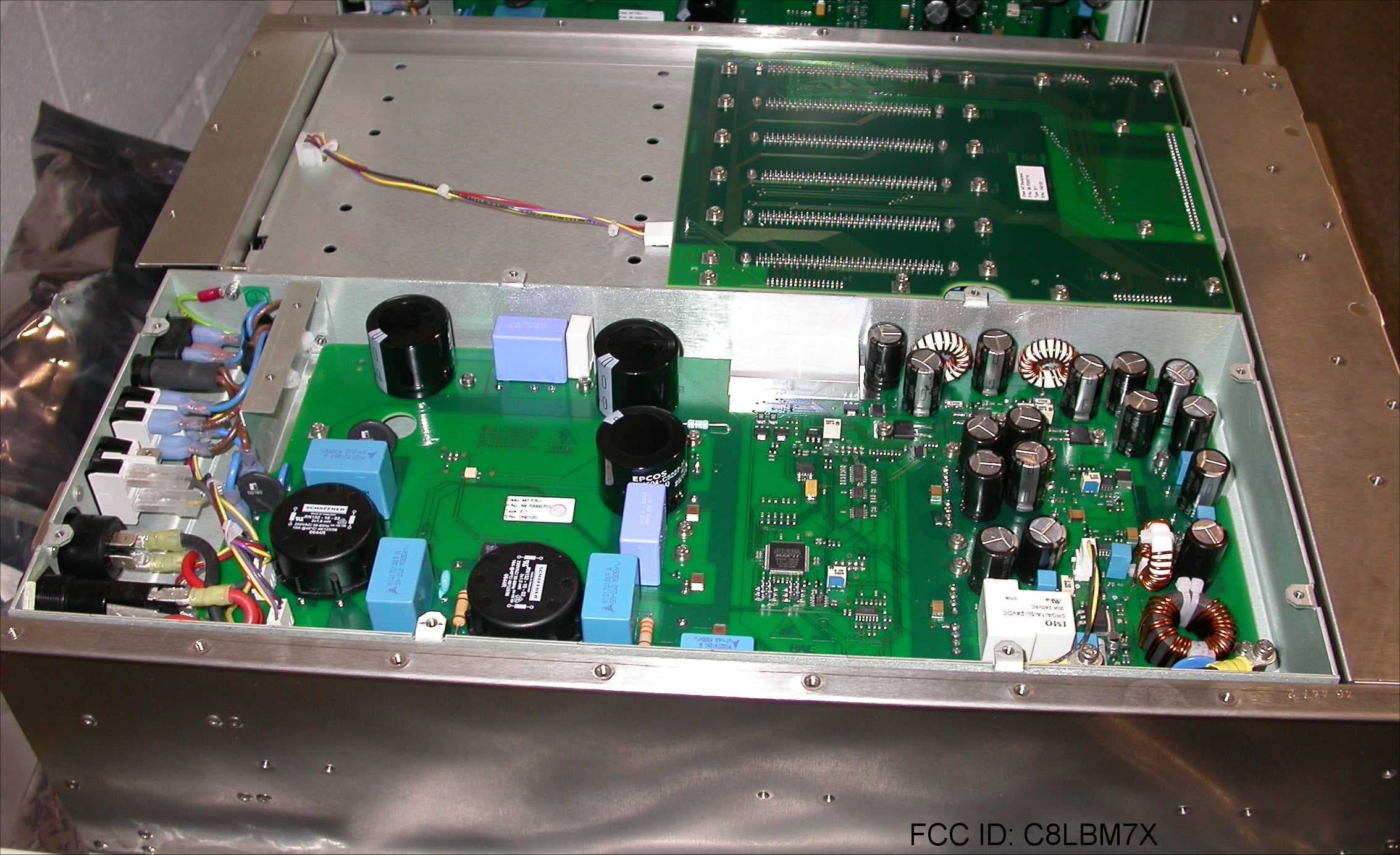
C8LBM7X
Feb 03, 200850W Transceiver
Equipment Class
TNB - Licensed Non-Broadcast Station Transmitter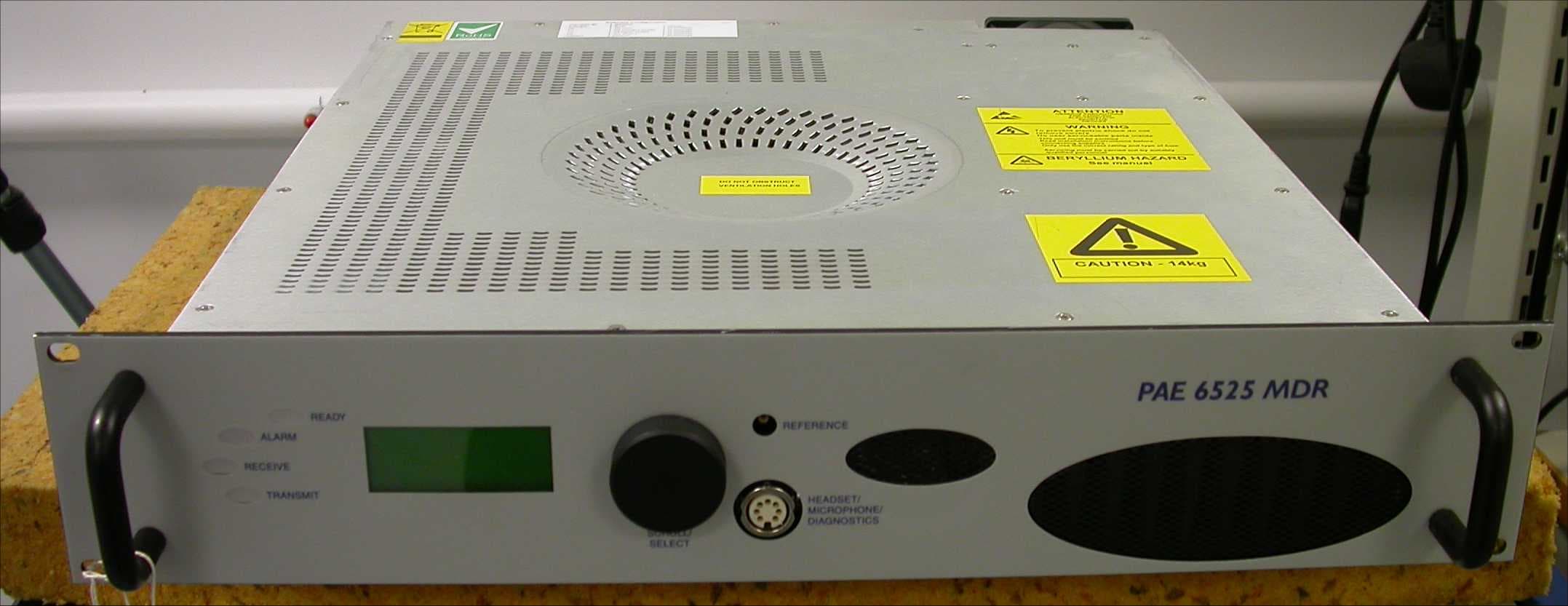
C8LB6525MDR
Aug 01, 2007Multimode VHF Ground to Air Transceiver
Equipment Class
TNB - Licensed Non-Broadcast Station Transmitter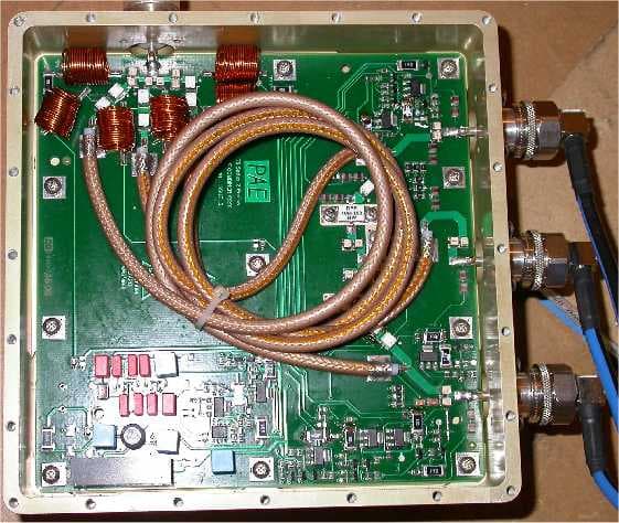
C8LB63300HS
Jun 06, 2007VHF Ground to Air Transmitter
Equipment Class
TNB - Licensed Non-Broadcast Station Transmitter
C8LB6350-S2
Oct 02, 2005VHF ground to air transmitter
Equipment Class
TNB - Licensed Non-Broadcast Station Transmitter
C8LB6100-S2
Oct 02, 2005VHF fixed ground based aeronautical receiver
Equipment Class
CXX - Communications Rcvr for use w/ licensed Tx and CBs