C8LB63300HSVHF Ground to Air Transmitter
Park Air Systems Limited
Click to zoom
Application Details
- Equipment Class
- TNB - Licensed Non-Broadcast Station Transmitter
- Date of Grant
- Jun 06, 2007
- Application Purpose
- Original Equipment
- Date of Application
- Jun 06, 2007
- Equipment Note
- VHF Ground to Air Transmitter
- Frequency Range
- 118.00000000 - 136.97500000
- Company
- Park Air Systems Limited
- Country
- United Kingdom
Documents & Files
Document Text
Text extracted from the exhibit documents filed with the FCC. Open a document above to read the original.
Users Manual
T6T 300 Watt VHF Transmitter User Documentation Page 2 Handbook Title:T6T 300 Watt VHF Transmitter User Documentation Handbook Part Number:31-3T6T300V Handbook Version: 1.1 Date of Issue: June 2006 Published By:Park Air Systems Northfields Market Deeping Peterborough PE6 8UE England Telephone:From UK, 01778 345434 From outside UK, 44 1778 345434 Fax:From UK, 01778 342877 From outside UK, 44 1778 342877 www.parkairsystems.com Errata Any errors found in this handbook, or associated equipment handbooks, are promulgated through the Park Air FTP network. Any user can access this information by logging on to: ftp.parkairsystems.com When logged on, select the public (Pub) folder, then the Handbook Errata Sheets folder, and then select the required equipment model. [Adobe Acrobat™ must be loaded on your PC to use this facility.] Health & Safety, EN 60950, CAN/CSA-C22.2 No. 60950, UL 60950. Radio IC RSS141, FCC part 15 and 87 . Page 4 Declaration of Conformity We, the undersigned, Company Park Air Systems Limited Address, City Northfields, Market Deeping, Peterborough PE6 8UE Country England Phone number +44 1778 345434 Fax number +44 1778 342877 certify and declare under our sole responsibility that the following equipment: Product description / Intended use Ground to air communications in the VHF aeronautical band EU / EFTA member states intended for use All countries Member states with restrictive use None Manufacturer Park Air Systems Limited Brand PAE Type T6T HS 300 , T6T HS 200 are tested to and conform with the essential requirements for protection of health and the safety of the user and any other person and Electromagnetic Compatibility, as included in following standards: Standard Issue date EN60950-1:2002 2002 EN60215 1989 EN301 489-1, EN301 489-22 06/2005, 11/2003 and is tested to and conforms with the essential radio test suites so that it effectively uses the frequency spectrum allocated to terrestrial/space radio communication and orbital resources so to as to avoid harmful interference, as included in following standards: Standard Issue date EN 300 676 V1.3.1 03/2003 and therefore complies with the essential requirements and provisions of the Directive 1999/5/EC of the European Parliament and of the council of March 9, 1999 on Radio equipment and Telecommunications Terminal Equipment and the mutual recognition of their conformity and with the provisions of Appendix IV (Conformity Assessment procedure referred to in article 10). The following Notified Body has been consulted in the Conformity Assessment procedure: Notified Body number Name and address 0336 TNO Certification B.V., PO Box 15, 9822 ZG Niekerk, The Netherlands The technical documentation as required by the Conformity Assessment procedure is kept at the following address: Company Park Air Systems Limited Address, City Northfields, Market Deeping, Peterborough PE6 8UE Country England Phone number +44 1778 345434 Fax number +44 1778 342877 TCF/TF reference nr. TCF-124-008 Drawn up in Northfields, Market Deeping, Peterborough PE6 8UE Date 10 October 2005 Name and position A. Horsfield consultant Engineer Page 5 Health and Safety T6T 300 Watt VHF Transmitter The T6T 300 watt VHF transmitter operates from a low voltage dc input supply, or a standard mains ac input supply. When using a mains supply, dangerous voltages are present on the rear panel ac connector and within the equipment. For this reason, only suitably qualified personnel should install and maintain the equipment. In use, an antenna is connected to the transmitter. During installation, consideration must be given regarding the resultant field strength in areas accessible to personnel. The formula to determine the field strength is given in the Installation topic. The output transistors used in the power amplifier (PA) of this transmitter contain the toxic material beryllium. Beryllium oxide dust is toxic if inhaled. Although no procedures in this documentation instruct component removal, users should be aware that there could be a hazard if a PA’s output transistors become physically damaged. The transmitter weighs approximately 79 kg. When lifting a transmitter, especially when fitting into an equipment cabinet, a minimum of two people should be used. Failure to do so can result in personal injury. Disposal This product is covered by the European Directive 2002/96/EC. It must not be disposed of in domestic waste. Disposal should be made using designated collection facilities appointed by the government or the local authorities in your area. Antenna Radiation WARNING Beryllium Hazard WARNING Lifting the Transmitter WARNING Page 6 Warnings and Cautions The following warnings and cautions are used in Park Air documentation. Warnings A warning is used to indicate possible danger to personnel. Throughout Park Air user documentation, warnings are indicated by the following symbols: Cautions A caution is used to indicate possible danger to the equipment. Throughout Park Air user documentation, cautions are indicated by the following symbols: Indicates electrical danger to personnel.WARNING Indicates a hazardous material.WARNING Indicates a non-ionizing radiation hazard. WARNING Indicates a specified danger to personnel. WARNING Indicates the presence of electrostatic sensitive devices (ESDs). Caution Indicates a specified danger to the equipment. Caution Page 7 Customer Support Contacting Park Air Customer support is available using email, telephone or fax. If you require help in configuring, installing or maintaining equipment supplied by Park Air, use any of the contact methods listed below. Email Address:[email protected] Telephone During normal UK office hours:+44 1778 381557 Outside normal UK office hours: +44 7733 124457 Fax Fax number:+44 1778 381556 Mail Address:Customer Services Department Park Air Systems Northfields Market Deeping Peterborough PE6 8UE England Web Site Web address:www.parkairsystems.com Fault Reporting To ensure that Park Air co…
Text truncated - open the document above for the full version.
Users Manual
T6T 300 Watt VHF TransmitterPage 79Installation Configuring the Transmitter for Operational Use The transmitter can be configured for use in several different ways. Typical configurations are illustrated in the following figures: Fig 19Local operation. Operating the transmitter using a microphone connected to the drive assembly front panel. Fig 20Remote operation. Operating the transmitter from a voice switch or remote controller. Fig 21With the transmitter connected through an RSE2 equipment. RSE2 is the remote site equipment in a Park Air Multi-Access Remote Control (MARC) system. This system provides automatic and manual main/standby switching and routes BIT information to allow radio, site and system status to be displayed at the control site. Fig 22With the transmitter connected through an E1 Radio Interconnect (E1-RIC). By using E1-RICs, a digital end-to-end system using E1 data streams can be configured. Fig 23The transmitter is configured with a receiver to provide Mode 2 operation (note that mode 2 software must be loaded to allow this configuration). Fig 24The transmitter is configured for Mode 3 operation (note that mode 3 software must be loaded to allow this configuration). The following pages show the illustrations listed above and then detail the pin-outs for the drive assembly connectors used to configure the transmitter for the required operational usage. The Microphone/ Diagnostics and the Reference connectors are fitted to the drive assembly’s front panel; other connectors, as shown in Fig 25, are fitted to the rear panel. T6T 300 Watt VHF TransmitterPage 80Installation Fig 19 Transmitter Configured for Local Operation Amplifier 1 Amplifier 2 Amplifier 3 Combiner Drive Assembly Reference Connector Microphone/Diagnostics Connector Microphone/Headset for transmissions and monitoring sidetone Laptop (or PC) required when using VFP Frequency Counter for Maintenance Facilities Connector Antenna change-over output Ready output Tape output BIT test input signal Inhibit input signal 28 Vdc output VSWR input signal PTT relay output E-BIT input Optional facilities (use as required) T6T 300 Watt VHF TransmitterPage 81Installation Fig 20 Transmitter Configured for Remote Operation Amplifier 1 Amplifier 2 Amplifier 3 Combiner Drive Assembly Reference Connector Microphone/Diagnostics Connector Microphone/Headset for engineering purposes Laptop (or PC) required when using VFP Frequency Counter for Maintenance Facilities Connector Antenna change-over output Ready output Tape output BIT test input signal Inhibit input signal 28 Vdc output VSWR input signal PTT relay output E-BIT input Optional facilities (use as required) MARC Connector or MARC Audio Connector Audio and PTT Signals from Control Equipment T6T 300 Watt VHF TransmitterPage 82Installation Fig 21 Transmitter Configured for use with a MARC RSE2 Amplifier 1 Amplifier 2 Amplifier 3 Combiner Drive Assembly Reference Connector Microphone/Diagnostics Connector Microphone/Headset for engineering purposes Laptop (or PC) required when using VFP Frequency Counter for Maintenance Facilities Connector Antenna change-over output Ready output Tape output BIT test input signal Inhibit input signal 28 Vdc output VSWR input signal PTT relay output E-BIT input Optional facilities (use as required) MARC Connector RSE2 Equipment Connectors Audio PTT MARC Data Audio and PTT from control equipment MARC Data to and from control centre T6T 300 Watt VHF TransmitterPage 83Installation Fig 22 Transmitter Configured for use with an E1-RIC Note: E1-RIC can be used in an E1 digital end-to-end system, or using 4-wire E and M lines. Amplifier 1 Amplifier 2 Amplifier 3 Combiner Drive Assembly Reference Connector Microphone/Diagnostics Connector Microphone/Headset for engineering purposes Laptop (or PC) required when using VFP Frequency Counter for Maintenance Facilities Connector Antenna change-over output Ready output Tape output BIT test input signal Inhibit input signal 28 Vdc output VSWR input signal PTT relay output E-BIT input Optional facilities (use as required) T1/E1 Connector E1-RIC Radio Connectors E1 Data Stream containing Audio, Signalling and Audio and PTT from control equipment MARC Data to and from control centre MARC Data E1 Data Stream containing Audio, Signalling and MARC Data Or (see Note) T6T 300 Watt VHF TransmitterPage 84Installation Fig 23 Transmitter Configured with Receiver for Mode 2 Operation Amplifier 1 Amplifier 2 Amplifier 3 Combiner Drive Assembly HDLC Connector Microphone/Diagnostics Connector Laptop (or PC) required when using VFP. Connects to Frequency Counter for Maintenance connects T1/E1 Connector T6R Receiver T1/E1 Connector Mode 2 Network Computer Antenna Connector Fast Antenna Change-Over Switch Facilities Connector Reference Connector Microphone/Diagnostics Connector Reference Connector to Reference Connector Microphone/Diagnostics Connector T6T 300 Watt VHF TransmitterPage 85Installation Fig 24 Transmitter Configured for Mode 3 Operation Amplifier 1 Amplifier 2 Amplifier 3 Combiner Drive Assembly Reference Connector Microphone/Diagnostics Connector Laptop (or PC) required when using VFP Frequency Counter for Maintenance T1/E1 Connector Mode 3 Network Computer T6T 300 Watt VHF TransmitterPage 86Installation Front Panel Connectors Microphone/Diagnostics Connector The Microphone/Diagnostics connector is a self-locking 7-way DIN socket used for connecting a microphone, microphone/headset or PC. The connector pin-out is detailed in Table 16. Reference Connector The Reference connector is an SMB plug used to monitor the radio’s reference frequency. It monitors the frequency at a level of 100 mV (±50 mV) with less than -10 dBc harmonics. Table 16 Microphone/Diagnostics Connector Pin NumberSignalCharacteristicUsage 1Microphone ground0 V.Microphone/Headset 2Transmit data RS232. 115200 baud, 8 data bits, 1 stop bit, no parity, no handshaking. PC 3Microphone PTT0 V to PTT.Microphone/Headset 4Receive dataRS232. 115200 baud, 8…
Text truncated - open the document above for the full version.
Attestation Statements
25 May 2007 RFI Global Services Limited Ewhurst Park Ramsdell Basingstoke Hampshire RG26 5RQ Reference FCC Filing for T6T HS 300 (C8LB63300HS) Dear Sirs, Regarding our application for FCC certification on the above product please be advised that there are no user tuneable parts on the equipment. Yours sincerely, Allan Horsfield Consultant Engineer EMC and Approvals Park Air Systems Ltd, Northfields, Market Deeping, Peterborough, PE6 8UE, England. Tel: +44 1778 345434 Fax: +44 1778 342877 www.parkairsystems.com Registered in England 1951792 A subsidiary of Northrop Grumman Corporation
Cover Letter(s)
Park Air Systems Ltd, Northfields, Market Deeping, Peterborough, PE6 8UE, England. Tel: +44 1778 345434 Fax: +44 1778 342877 www.parkairsystems.com Registered in England 1951792 A subsidiary of Northrop Grumman Corporation To: Telefication B.V. Attn: Dept. FCC TCB Edisonstraat 12A 6902 PK ZEVENAAR The Netherlands Subject: Request for confidentiality FCC ID:C8LB63300HS Reference number: 63300CAAH Dear FCC TCB, Persuant to 47 CFR Section 0.459(a) & (b), Park Air Systems hereby requests non-disclosure and confidential treatment of the following materials submitted in support of FCC certification application for FCC ID: (C8LB63300HS) Bill(s) of Material Block Diagrams Operational Description Schematic Diagrams Above materials contain secrets, proprietary and technical information, which would customarily be quarded from competitors under 47 CFR, section 0.457(d)(2). Disclosure or publication or any portion of this company confidential material to other parties could cause substantial competitive harm and provide unjustified benefits for competitors. Park Air Systems Ltd.understands that pursuant to 47 CFR section 0.457(d)(1)(ii) disclosure of the applicant and all accompanying documentation will not be made before the date of the grant. Market Deeping 05/14/2007 Allan Horsfield Consultant Engineer
Cover Letter(s)
12 July 2006 Donald K Willis Manager Spectrum Planning and International Office FAA Spectrum Engineering Division 800 Independence Avenue SW Washington, DC 20591 Dear Sir, Please be advised that we are about to undertake a FCC certification through our local test facility, RFI Global Services Limited. The equipment involved is a high power transmitter for ground to air communication in the 118-136.975 MHz band. The product is designed for extended coverage applications and produces either 200W or 300W dependant on model. The transmitters comprise a drive unit, a combiner and either 2 or 3 100W amplifier assemblies. We currently, only have a Canadian requirement for this equipment but would also like to make it available in America so the testing will cover both countries. I understand that there is a maximum power output of 200W normally applicable to this band, and both products can be set from below 50W to full power. All performance parameters are the same as the 100W transmitter C8LB63100HS. If you could address any concerns or objections to myself or RFI Global Services I would be grateful. Yours faithfully, Allan Horsfield Consultant Engineer EMC and Approvals Email: [email protected] CAB: RFI Global Services Limited, Ewhurst Park, Ramsdell, Basingstoke Hampshire, England RG26 5RQ (email: [email protected]) Park Air Systems Ltd, Northfields, Market Deeping, Peterborough, PE6 8UE, England. Tel: +44 1778 345434 Fax: +44 1778 342877 www.parkairsystems.com Registered in England 1951792 A subsidiary of Northrop Grumman Corporation FAA Notification of FCC Type Acceptance Application for T6 Series 200W/300W Ground to Air Transmitters. General FCC Number (proposed) T6T HS 200 A 200W transmitter C8LB63200HS T6T HS 300 A 300W transmitter C8LB63300HS Manufacturer Park Air Systems Ltd. England. RF Output Power 200/300Watts Antenna port 50R N-type connector Frequency range 118 MHz to 136.975 MHz. Method of tuning Frequency selected by front panel control and LCD display. Channelling capability 25 kHz (8.33kHz capable). Emission bandwidth Within FCC limits see attached report summary Emission type 6K00A3E Emission/harmonics EMC All products are Type examined under the EMC Directive to comply with emission and immunity requirements to Class B. Certificates attached. Safety All equipment is designed to comply with EN60950. This equipment will also be certified to UL 60950 and CSA 22.2 No. 60950. Description Park Air Systems T6 series are VHF multi-mode air-traffic control radios compatible with analogue (AM) and digital (D8PSK) modulation modes. Current models are supplied programmed for AM voice operation in the frequency range 118 to 136.975 MHz using 25 kHz or 8.33 kHz channel spacing. The latter is disabled through front panel settings for the American market. This transmitter produces a 200W/300W carrier output that can be reduced, in steps, to 20/30W. The output power, and the majority of operational settings, can be selected at the front panel, using the virtual front panel (VFP) on a pc, or through a compatible control and data system such as the PAE multi-access remote control (MARC) system. A multi-channel feature allows up to 100 frequency channels to be stored and recalled by channel number. The equipment is designed to be fitted in an industrial 19 inch (483 mm) equipment rack. Operation is from either a standard ac mains supply, or from a low voltage dc supply. When both input supplies are connected, the dc supply acts as a back-up if the mains supply fails. Comprehensive continuous and interruptive Built-In Tests (BIT) provide confidence of the radios serviceability. The transmitters are based on current 50W and 100W approved models: T6T 50W VHF AM transmitter under filing C8LB6350-S2 T6T HS 100 VHF 100W AM transmitter under filing C8LB63100HS The driver comprises a T6T 50W transmitter with the power amplifier replaced by a drive module. The amplifier consists of a T6T HS 100 with the processor and power amplifier control modules replaced by a simple interface. Outputs from the amplifiers are then combined in an external combiner module. This unit uses DC sensing to determine whether the equipment is 200W or 300W and also to confirm cables are correctly configured. All transmitters employ the same processor control module, power amplifiers and power supplies that were employed in the previously approved 100W transmitter. T6T HS 300 Occupied Bandwidth - 47 CFR 2.1049 (1) Measured at 127.5 MHZ Power output: 300W Result : 5.15kHz Authorized bandwidth: 25 kHz Same results also measured at 118 and 136.975 MHz Harmonic Output Specification: Measured at 127.5MHz, 300W carrier; the typical harmonic output was measured at 2Fc -36dBm 3Fc -36.3dBm All higher harmonics < -40dBm Non harmonic spurious output specification: -46 dBm. UK EMC Type Certification Equipment Photos Example 300W configuration in mini rack: The 200W version has two amplifiers rather than the three shown above 100W Amplifier front view 100W Amplifier rear view 200W transmitter comprises 2 amplifiers , a drive unit and a combiner module 300W transmitter comprises 3 amplifiers , a drive unit and a combiner module Drive unit front view Drive unit rear view Combiner module for 200 or 300 Watt: For 200W transmitter one port is left open
Cover Letter(s)
25 May 2007 RFI Global Services Limited Ewhurst Park Ramsdell Basingstoke Hampshire RG26 5RQ Reference FCC Filing for T6T HS 300 (C8LB63300HS) Dear Sirs, This application for certification was initiated in July 2006 and at that time it was intended to Certify two models under FCC ID’s C8LB63200HS and C8LB63300HS and this is reflected in the positive response we received from Mr Frazier at the FAA. We have since been advised that as the transmitter is made up from a number of amplifiers we do not need to use two different FCC ID’s and therefore we request that any reference to C8LB63200HS should be disregarded and our application shall only be for FCC ID C8LB63300HS as a 300W transmitter. Yours sincerely, Allan Horsfield Consultant Engineer EMC and Approvals Park Air Systems Ltd, Northfields, Market Deeping, Peterborough, PE6 8UE, England. Tel: +44 1778 345434 Fax: +44 1778 342877 www.parkairsystems.com Registered in England 1951792 A subsidiary of Northrop Grumman Corporation
ID Label/Location Info
FCC Labelling of transmitters: 300W FCC ID: C8LB63300HS Part 15 label on each part:
Operational Description
12 July 2006 Donald K Willis Manager Spectrum Planning and International Office FAA Spectrum Engineering Division 800 Independence Avenue SW Washington, DC 20591 Dear Sir, Please be advised that we are about to undertake a FCC certification through our local test facility, RFI Global Services Limited. The equipment involved is a high power transmitter for ground to air communication in the 118-136.975 MHz band. The product is designed for extended coverage applications and produces either 200W or 300W dependant on model. The transmitters comprise a drive unit, a combiner and either 2 or 3 100W amplifier assemblies. We currently, only have a Canadian requirement for this equipment but would also like to make it available in America so the testing will cover both countries. I understand that there is a maximum power output of 200W normally applicable to this band, and both products can be set from below 50W to full power. All performance parameters are the same as the 100W transmitter C8LB63100HS. If you could address any concerns or objections to myself or RFI Global Services I would be grateful. Yours faithfully, Allan Horsfield Consultant Engineer EMC and Approvals Email: [email protected] CAB: RFI Global Services Limited, Ewhurst Park, Ramsdell, Basingstoke Hampshire, England RG26 5RQ (email: [email protected]) Park Air Systems Ltd, Northfields, Market Deeping, Peterborough, PE6 8UE, England. Tel: +44 1778 345434 Fax: +44 1778 342877 www.parkairsystems.com Registered in England 1951792 A subsidiary of Northrop Grumman Corporation FAA Notification of FCC Type Acceptance Application for T6 Series 200W/300W Ground to Air Transmitters. General FCC Number (proposed) T6T HS 200 A 200W transmitter C8LB63200HS T6T HS 300 A 300W transmitter C8LB63300HS Manufacturer Park Air Systems Ltd. England. RF Output Power 200/300Watts Antenna port 50R N-type connector Frequency range 118 MHz to 136.975 MHz. Method of tuning Frequency selected by front panel control and LCD display. Channelling capability 25 kHz (8.33kHz capable). Emission bandwidth Within FCC limits see attached report summary Emission type 6K00A3E Emission/harmonics EMC All products are Type examined under the EMC Directive to comply with emission and immunity requirements to Class B. Certificates attached. Safety All equipment is designed to comply with EN60950. This equipment will also be certified to UL 60950 and CSA 22.2 No. 60950. Description Park Air Systems T6 series are VHF multi-mode air-traffic control radios compatible with analogue (AM) and digital (D8PSK) modulation modes. Current models are supplied programmed for AM voice operation in the frequency range 118 to 136.975 MHz using 25 kHz or 8.33 kHz channel spacing. The latter is disabled through front panel settings for the American market. This transmitter produces a 200W/300W carrier output that can be reduced, in steps, to 20/30W. The output power, and the majority of operational settings, can be selected at the front panel, using the virtual front panel (VFP) on a pc, or through a compatible control and data system such as the PAE multi-access remote control (MARC) system. A multi-channel feature allows up to 100 frequency channels to be stored and recalled by channel number. The equipment is designed to be fitted in an industrial 19 inch (483 mm) equipment rack. Operation is from either a standard ac mains supply, or from a low voltage dc supply. When both input supplies are connected, the dc supply acts as a back-up if the mains supply fails. Comprehensive continuous and interruptive Built-In Tests (BIT) provide confidence of the radios serviceability. The transmitters are based on current 50W and 100W approved models: T6T 50W VHF AM transmitter under filing C8LB6350-S2 T6T HS 100 VHF 100W AM transmitter under filing C8LB63100HS The driver comprises a T6T 50W transmitter with the power amplifier replaced by a drive module. The amplifier consists of a T6T HS 100 with the processor and power amplifier control modules replaced by a simple interface. Outputs from the amplifiers are then combined in an external combiner module. This unit uses DC sensing to determine whether the equipment is 200W or 300W and also to confirm cables are correctly configured. All transmitters employ the same processor control module, power amplifiers and power supplies that were employed in the previously approved 100W transmitter. T6T HS 300 Occupied Bandwidth - 47 CFR 2.1049 (1) Measured at 127.5 MHZ Power output: 300W Result : 5.15kHz Authorized bandwidth: 25 kHz Same results also measured at 118 and 136.975 MHz Harmonic Output Specification: Measured at 127.5MHz, 300W carrier; the typical harmonic output was measured at 2Fc -36dBm 3Fc -36.3dBm All higher harmonics < -40dBm Non harmonic spurious output specification: -46 dBm. UK EMC Type Certification Equipment Photos Example 300W configuration in mini rack: The 200W version has two amplifiers rather than the three shown above 100W Amplifier front view 100W Amplifier rear view 200W transmitter comprises 2 amplifiers , a drive unit and a combiner module 300W transmitter comprises 3 amplifiers , a drive unit and a combiner module Drive unit front view Drive unit rear view Combiner module for 200 or 300 Watt: For 200W transmitter one port is left open
RF Exposure Info
T6T 300 Watt VHF TransmitterPage 68Installation Warnings and Cautions The instructions given in this topic involve connecting dangerous voltage to the transmitter and should be carried out only by suitably qualified personnel. The equipment is permanently connected to the mains supply when the mains connectors are attached. Switching the rear panel Supply switch to off does not isolate all internal circuits from the mains supply. For this reason, a mains isolating switch should be fitted close to, and easily accessible from, the transmitter's position. The isolation switch should isolate both live and neutral supplies to the IEC connectors fitted to the drive assembly and amplifiers, be clearly labelled, and adequately rated to protect the equipment. The antenna used with the transmitter must be installed such that the resultant radiated field strength is below 10 W/m² in areas normally accessible to personnel. The RF field strength from the antenna can be predicted from the equation S=1.4PG/4πR 2 [Where S = power density; P = power input to antenna; G = antenna gain; R = distance to centre of radiation and 1.4 = multiplication factor for average power based on a modulation index of 90%.] Based on this formula for a 300 watt transmitter and using a 0 dBi antenna, the predicted safe distance from the centre of radiation would be approximately 1.8 m for a field strength of 10 W/m 2 (1 mW/cm 2 ). This meets the requirements of Health Canada Safety Code 6 for RF and microwave exposed workers. For persons not classed as RF and microwave workers and including the general public the limit is 2 W/m 2 (0.2 mW/cm 2 ) which increases the minimum safe distance to 4.1 m. Further information on calculating the field strengths and power levels can be found in Health Canada Safety Code 6 'Limits of Human Exposure to Radiofrequency Electromagnetic Fields in the Frequency Range 3 kHz to 300 GHz', and also in FCC document OET Bulletin 65. The T6T transmitter's circuitry contains Electrostatic Sensitive Devices (ESDs). Personnel must be aware of the precautions necessary to prevent damage to such devices. During installation all precautions necessary to prevent ESD damage must be taken. Changes or modifications made to this equipment that are not expressly approved by Park Air, or parties authorized by Park Air, could void the user’s authority to operate the equipment. WARNINGDangerous Voltage WARNINGDangerous Voltage WARNING Antenna Radiation Caution ESDs Caution Unauthorized Modifications
Test Report
TEST REPORT FROM RFI GLOBAL SERVICES LTD Test of: Park Air Systems Ltd. T6T HS 300 300 Watt VHF Gound to Air Transmitter To: FCC Part 87: 2005 Test Report Serial No: RFI/RPTE2/RP48505JD02A Supersedes Test Report Serial No: RFI/RPTE1/RP48505JD02A This Test Report Is Issued Under The Authority Of Michael Derby, Operations Manager: Tested By: Charlton Fergus pp Checked By: Michael Derby pp Report Copy No: PDF01 Issue Date: 24 May 2007 Test Dates: 08 August 2006 to 11 August 2006 This report is issued in Adobe Acrobat portable document format (PDF). It is only a valid copy of the report if it is being viewed in PDF format with the following security options not allowed: Changing the document, Selecting text and graphics, Adding or changing notes and form fields. This report may be copied in full. The results in this report apply only to the sample(s) tested. RFI GLOBAL SERVICES LTD TEST REPORT S.No. RFI/RPTE2/RP48505JD02A Page: 2 of 61 Issue Date: 24 May 2007 Test of: Park Air Systems Ltd. T6T HS 300 300 Watt VHF Gound to Air Transmitter To: FCC Part 87: 2005 This page has been left intentionally blank. RFI GLOBAL SERVICES LTD TEST REPORT S.No. RFI/RPTE2/RP48505JD02A Page: 3 of 61 Issue Date: 24 May 2007 Test of: Park Air Systems Ltd. T6T HS 300 300 Watt VHF Gound to Air Transmitter To: FCC Part 87: 2005 Table of Contents 1. Client Information ......................................................................................................... 4 2. Equipment Under Test (EUT) ....................................................................................... 5 3. Test Specification ......................................................................................................... 7 4. Deviations from the Test Specification ...................................................................... 8 5. Operation of the EUT during …
Text truncated - open the document above for the full version.
Contact Information
Applicant
Philip Ackerman(Consultant Engineer)
Test Firm
RFI Global Services Ltd.Allan Hume
Technical Specifications
| # | Rule Parts | Frequency Range | Power Output | Emission | Tolerance |
|---|---|---|---|---|---|
| 2 | 87 | 118 MHz - 136.975 MHz | 200 W | 6K0A3E | 0.3 ppm |
Other Applications from Park Air Systems Limited
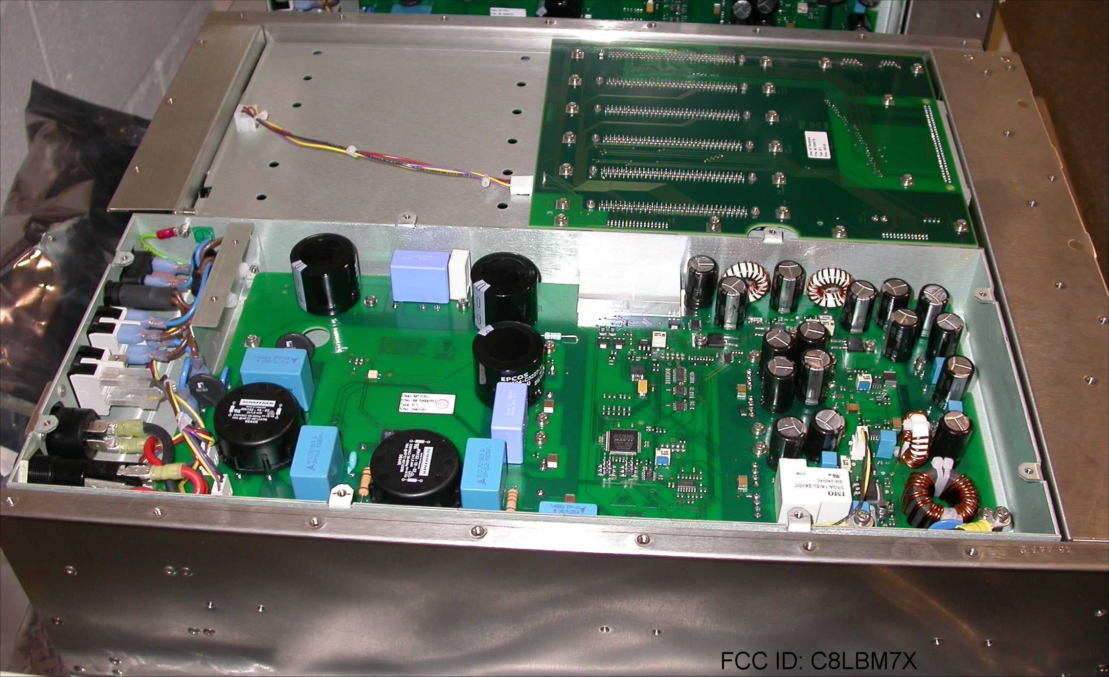
C8LBM7X
Feb 03, 200850W Transceiver
Equipment Class
TNB - Licensed Non-Broadcast Station Transmitter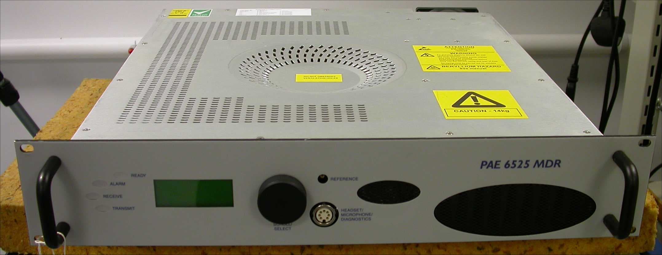
C8LB6525MDR
Aug 01, 2007Multimode VHF Ground to Air Transceiver
Equipment Class
TNB - Licensed Non-Broadcast Station Transmitter
C8LB6350-S2
Oct 02, 2005VHF ground to air transmitter
Equipment Class
TNB - Licensed Non-Broadcast Station Transmitter
C8LB6100-S2
Oct 02, 2005VHF fixed ground based aeronautical receiver
Equipment Class
CXX - Communications Rcvr for use w/ licensed Tx and CBs
C8LB6550-S2
Sep 29, 2005VHF ground to air transceiver
Equipment Class
TNB - Licensed Non-Broadcast Station Transmitter