C8LB6100VHF Fixed Ground Based Aeronautical Receiver
Park Air Systems Limited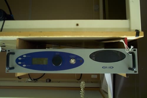
Click to zoom
Application Details
- Equipment Class
- CXX - Communications Rcvr for use w/ licensed Tx and CBs
- Date of Grant
- Apr 25, 2000
- Application Purpose
- Original Equipment
- Date of Application
- Mar 29, 2000
- Equipment Note
- VHF Fixed Ground Based Aeronautical Receiver
- Frequency Range
- 118.00000000 - 136.97500000
- Company
- Park Air Systems Limited
- Country
- United Kingdom
Documents & Files
Document Text
Text extracted from the exhibit documents filed with the FCC. Open a document above to read the original.
Users Manual
T6R Receiver User Guide Issue 1 Handbook Title:T6R Receiver User Guide Handbook Part Number:31-360000RX Issue Number:1 Date of Issue:November 1999 Published By:Park Air Electronics Northfields Market Deeping Peterborough England PE6 8UE Telephone:From UK,01778 345434 From outside UK, 44 1778 345434 Fax:From UK,01778 342877 From outside UK, 44 1778 342877 Page ii Handbook Amendment Record Amendments to this handbook, originated by Park Air Electronics, are listed in the following table. Amendment Number DateBrief Details PAE Change Note Number Equipment Modification Record Modifications to the T6R receiver are detailed in the following table. The equipmentís modification label shows all modifications embodied in the equipment. Modification Number DateBrief Details PAE Change Note Number Page iii List of Abbreviations The following abbreviations are used in this user guide: Page iv Aamp AMamplitude modulation BITbuilt-in test dBdecibel DSPdigital signal processing ETIelapsed time indicator ICAOinternational civil aviation organisation kgkilogram kHzkilo Hertz LCDliquid crystal display mAmilliamp MARC multi-access remote control system MHzmega Hertz mmmillimetre ppmparts per million PSKphase shift keying rmsroot mean square RSSIreceiver signal strength indication Vvolt VFPvirtual front panel VHFvery high frequency T6R Receiver User Guide Section 1 General Information T6R General InformationSection 1 Page 1 Section 1T6R General Information Page 2 Section 1 Contents Chapter 1.Overview Introduction to the T6R Receiver3 T6R Handbooks3 Operational Settings4 Virtual Front Panel5 Built-In Tests5 Configuring the T6R Receiver6 Chapter 2.Specification Dimensions and Weight9 RF Characteristics9 Environmental9 Power Requirements10 Chapter 3.Controls, Indicators, and Connectors Front Panel11 Receive Indicator11 Alarm Indicator11 Ready Indicator11 Standby Indicator11 Reference Connector12 Headset/Diagnostics Connector12 Scroll/Select Switch and LCD13 Rear Panel14 Power Switch14 AC Input Connector14 DC Input Connector15 Fuse F115 Chassis Stud Connection15 Facilities Connector CN515 MARC Port CN616 Computer Port CN716 Antenna Connector16 Chapter 4.Installation Procedures Introduction21 Initial Inspection of the Receiver22 Fitting the Correct AC Input Fuse22 Fitting a Radio into an Equipment Rack23 Connecting Remote Facilities23 Chassis Stud Connection24 AC Supply Connection24 DC Supply Connection25 Connecting an Antenna25 Switching on25 Page Chapter 1.Overview This chapter provides an introduction to the T6R receiver, briefly describes the features, and shows how the radio is configured for operational use. INTRODUCTION TO THE T6R RECEIVER Park Air Electronics (PAE) T6R is a VHF multi-mode air traffic control receiver compatible with analogue (AM) and digital (D8PSK) modulation modes. Current models are supplied programmed for AM voice operation in the frequency range 118 to 136.975 MHz using 25 kHz or 8.33 kHz channel spacing. Future software upgrades will allow D8PSK operation. A multi-channel feature of the receiver allows up to 100 channels to be stored, and recalled by channel number. Channel designation and all operational settings can be selected from the front panel, or by using the virtual front panel (VFP), or through a compatible control and data system such as the PAE multi-access remote control (MARC). The receiver is designed to be fitted in an industrial 19 inch (483 mm) equipment rack. Operation is from either a standard ac mains supply, or from a low voltage dc supply. When both input supplies are connected, the dc supply acts as a back-up if the mains supply fails. Comprehensive continuous and interruptive Built-In Tests (BIT) provide confidence of the receiver's serviceability. T6R HANDBOOKS This user guide describes the T6R receiver and gives complete installation and setting up procedures. The user guide is split into sections as follows: Section 1.Section 1 (this section) provides general information that is common to all operating modes. Section 2.Section 2 provides information that is specific to operating the T6R receiver in AM-voice mode. Section 3.Section 3 onwards will, when available, describe the digital operating modes. A maintenance kit (PAE part number 70-6100MKIT) is also available. A maintenance handbook, included in the kit, contains fault finding guides to module level and details VFP operation. The VFP can be used for setting up, maintenance purposes, and for loading new software. The maintenance kit includes a CD-ROM containing the VFP software, and a lead for connecting the radio to a Personal Computer (PC). The CD-ROM also contains the software as loaded into the T6R at the time of sale. This enables the original software to be re-loaded if the receiver's Digital Signal Processing (DSP) module is ever replaced. Both the user guide and maintenance handbook are available on CD ROM. Contact PAE for details. T6R General InformationSection 1 Page 3 T6R receiver maintenance should not be attempted without reference to the maintenance handbook OPERATIONAL SETTINGS Operational settings for the T6R receiver are configured at the front panel, through the VFP, or through an associated MARC system (or compatible control and data system). At the receiver, operational settings are selected and displayed using the front panel Scroll/Select switch and the LCD. The settings are selected through a series of menus. Full details are given in the section of this user guide applicable to the operating mode. Two example selection menus, Set Frequency menu and Channel Storage menu, are shown below. 121 . 500MHz Cance lOK Ch100121 . 500MHz Cance l Store Storeand End During normal receiver operation, the Main screen, shown below, is displayed. The screen shows the operating frequency, the channel number (if the channel store facility is used), and displays a graphical representation of volume. Fr eq123 . 000MHz Chan1 VollllIIIIIIIII Section 1T6R General Information Page 4 Freq123.000MHz Chan…
Text truncated - open the document above for the full version.
Users Manual
PARKAIRELECTRONICST6R VHF RECEIVER Description Digital Multimode Receiver PARKAIRELECTRONICS FEATURES Analogue and Digital programmable modulation modes AM voice with 25 kHz and 8.33 kHz channel spacing AM-MSK for Mode 1 (ACARS) D8PSK for Mode 2 (CSMA) and Mode 3 (TDMA) Exceptional dynamic range and co-location performance Compact 2U high rack mounting package Class leading RF performance Static and dynamic BIT The T6 Series represent the latest generation of Park Air ATC radios which are designed for professional applications in airport and en-route centres. The T6 Series fulfils both analogue (AM) modulation and the future digital (D8PSK) modes, which are being planned by ICAO. The T6 Series makes extensive use of advanced DSP (digital signal processing) technology to enable the transition from analogue to digital modulation modes to be made via software upgrade. Investment in radio systems is thereby pro- tected against obsolescence as new digital modulation waveforms are introduced. The T6R operates in the VHF aviation band and provides both 25KHz and 8.33KHz channel spacing. A 100 channel memory is incorporated for recall of pre-set frequency and operating modes in multichannel applications. All demodulation is implemented using DSP algorithms, which provide consistent long term performance. D8PSK digital modula- tion waveforms require high performance demodulators to ensure reliable synchronisation and low BER (bit error rate) at low signal levels. The T6R employs specially developed algo- rithms allied to high performance RF circuitry to ensure optimum performance in this critical area. Control of receiver operating parameters can be effected locally using a menu driven front panel LCD or remotely via serial ports on the rear panel. All receiver adjustments are under software control and can be accessed externally avoiding any necessity to remove covers during the operational life of the equipment. Should software updates be required to support new modulation modes in the future, these can be simply effected via a front panel diagnostic port or remotely via rear panel serial ports. The T6R has comprehensive BIT which monitors both static (supplies etc) and dynamic (S+N/N, etc) parameters. A novel technique provides an accurate assessment of receiver sensitivity using BIT. Results can be viewed on the front panel LCD and are summarised via READY and ALARM indicators. All BIT data is available for remote monitoring via the serial ports and receivers can be readily networked for remote monitoring using PAE MARC or similar systems. The receiver is a compact 2U 19” rack mounted unit. Power can be 110/220 VAC or 24/28 VDC, with automatic switching to DC in the event of an AC failure. Both inputs are fully filtered and protected. Specification Digital Multimode Receiver PARKAIRELECTRONICST6R VHF RECEIVER UK HEAD OFFICE: Northfields, Market Deeping, Peterborough, PE6 8UE, England. Tel + 44 1778 345434 Fax + 44 1778 341286 USA: Tel +1 410 349 8629 Fax +1 410 349 1846 FAR EAST: Tel +603 706 4898 Fax +603 706 4775 Email: [email protected] Web site: www.parkair.co.uk Park Air Electronics Ltd is a subsidiary of Northrop Grumman PARKAIRELECTRONICS General Characteristics Frequency range: 117.975 to 136.975 MHz Channel spacing: 25 KHz and 8.333 KHz Programmable Channels 100 Frequency error: ±1 ppm Modulation mode AM voice AM-MSK D8PSK Mode 2 and Mode 3 Power supplies: ac: 110/120/220/240 V (±10%), 45 to 65 Hz <75 VA max dc: 21.4 to 32 V <2 A Environmental: Operating: -20 to +55 degrees C Storage: -30 to +70 degrees C EMC/EMI: 89/336/EEC Weight/Dimensions Width: 483 mm (19 inches) Height: 2U/89 mm (3.5 inches) Depth: 419 mm (16.5 inches) Weight: 6kg RF Characteristics Sensitivity AM -107 dBm for 10 dB S+N/N D8PSK -103dBm for 1x10 -3 BER (without FEC) Synchronisation Probability D8PSK 0.999 for -103 dBm signal Selectivity 25 KHz channels ±11 KHz for 6 dB ±25 KHz for 80 dB 8.33 KHz channels ±3.5 KHz for 6 dB ±8.33 KHz for 70 dB Spurious signal suppression <2 MHz from carrier -80 dB >2 MHz from carrier -100 dB Intermodulation >75 dB for signals >100 KHz from carrier Cross Modulation -10 dBm for signals >1% from carrier Modulation Characteristics (AM) Response 25KHz channel spacing: 300 Hz to 3.4 KHz ±3 dB ref 1 KHz >20 dB attenuation at 100 Hz >30 dB attenuation at 5 KHz Response 8.33KHz channel spacing: 350 Hz to 2.5KHz ±3 dB ref 1 KHz >20 dB attenuation at 100 Hz >25 dB attenuation at 5 KHz Distortion: <5% THD at 80% modulation AGC: <3 dB change in audio output for RF signals between - 107 dBm and +10 dBm <1 dB change in audio output for modulation depth change between 30% and 90% Mute: Noise compensated, range <6 to >16 dB S+N/N Audio outputs 600 ohm balanced line adjustable -20 dBm to +10 dBm Front panel loudspeaker 1 W nominal Front Panel Facilities: A rotary encoder and back lit 4-line LCD provide simple menu driven control of all receiver operating parame- ters and BIT functions LED indicators for standby, ready, alarm and receive Combined headphone and diagnostic port connector Recessed co-axial connector for monitoring internal ref- erence oscillator Loudspeaker Rear Panel Facilities: Antenna: N-type female connector Supply connectors ac and dc supply connectors with associated fuses Facilities connector 15-way D-type includes audio, control, and BIT con- nections Data connector 25-way D-type used to link receiver to control comput- er when operating in digital modes. Provides two RS422 synchronous HDLC interfaces for status/ control and transmission data plus real time data and timing for TDMA. Message protocol and packet structures con- form to ICAO/VDL SARPS requirements. MARC connector 9-way D-type provides independent connection of audio/serial control data to MARC remote control and monitoring systems.
Cover Letter(s)
Northfields, Market Deeping, Peterborough, PE6 8UE, England. Tel: +44 (0) 1778 345434 Fax: 342877 Sales Fax: 341286 www.parkair.co.uk Registered in England 1951792 An ISO9001 Approved Company A subsidiary of Northrop Grumman Corporation 20 March 2000 Federal Communications Commission Equipment Approval Services P.O. Box 358315 Pittsburgh PA 15251-5315 USA Dear Sirs, Please find enclosed an application for Type Certification of a receiver under Part 15 rules. This equipment is a VHF AM receiver model number B6100 for ground to air communication use in licensed installations. Should you require further information in support of this application please do not hesitate to contact me. Yours faithfully, Allan Horsfield Principal Engineer EMC and Approvals Message: Commercial, in Confidence
Cover Letter(s)
Northfields, Market Deeping, Peterborough, PE6 8UE, England. Tel: +44 (0) 1778 345434 Fax: 342877 Sales Fax: 341286 www.parkair.co.uk Registered in England 1951792 An ISO9001 Approved Company A subsidiary of Northrop Grumman Corporation 15 March 2000 Federal Communicatio ns Co mmission Equipment Approval Services PO Box 358315 Pittsb urgh PA 15251-5315 Reference: C8LB6100 731 Confirmation No. Request for Confidentiality Dear Sir or Madame, Park Air Electronics respectfully requests that all circuit diagrams provided for this application should be regarded as Company Confidential and not made available to third parties. The product includes advanced digital signal processing technology w hich ensures the Company remains a world leader in this field of communications. Yours faithfully, Allan Horsfield Principal Engineer EMC and Approvals
Cover Letter(s)
PAE T6R Receiver Model 6100 C8L6100 FCC ApplicationPage 1 of 1 ---------------------------------------------------------------------------------------------------------------------------------------------- ------ LIST OF EXHIBITS EXHIBIT AFCC Identification label position illustration Photograph of equipment ; front view Photograph of equipment ; rear view Photograph of equipment ; internal view - top Photograph of equipment ; internal view - bottom Photographs of dsp modules EXHIBIT BTest Report for FCC Certification EXHIBIT CEquipment Block Diagram EXHIBIT DOperators User Guide and Technical Specification EXHIBIT ECircuit Diagrams EXHIBIT FSales Leaflet
Cover Letter(s)
Northfields, Market Deeping, Peterborough, PE6 8UE, England. Tel: +44 (0) 1778 345434 Fax: 342877 Sales Fax: 341286 www.parkair.co.uk Registered in England 1951792 An ISO9001 Approved Company A subsidiary of Northrop Grumman Corporation 26 April 2000 Federal Communicatio ns Co mmission Equipment Approval Services PO Box 358315 Pittsb urgh PA 15251-5315 Reference: C8LB6100 731 Confirmation No. Request for Confidentiality Dear Sir or Madame, Park Air Electronics respectfully requests that all circuit diagrams and block diagrams, provided for this application, should be regarded as Company Confidential and not made available to third parties. The product includes advanced digital signal processing technology which ensures the Company remains a world leader in this field of communications. Yours faithfully, Allan Horsfield Principal Engineer EMC and Approvals
External Photos
EXHIBIT A2 Photographs Front view Rear View (label position )
ID Label/Location Info
EXHIBIT A Model number label and location This equipment is intended for operation with associated transmitter PAE B6350 for which a separate filing application (C8LB6350) has been made under Pt 87 of the FCC Rules. EQUIPM ENT T6R VHF FREQ SER No. JOB No. CUSTOM ER NAME VOLTS AC ~ 28 DC QA STAMP TEST STAMP (B6100) T6R M ain Assem bly Page 9 Issue 1 Fit Top and bottom covers and Labels Also on bottom cover Model label with FCC identifier Text label placed above main label
Internal Photos
Exhibit A3 Photographs Top view (PSU & DSP Modules) Exhibit A3 Photographs Bottom view (RF Module)
Internal Photos
Exhibit A4 Photographs DSP Module (from top
Test Report
EQUIPMENT : T6R/B6100 TEST REPORT NUMBER: CTMS 2000/1221B FCC Identifier : C8L B6100 CTMS FCC Registration Number : 93385 Page 1 of 18 TEST REPORT ON Park Air VHF AM Receiver FCC Procedures Part 15 TEST REPORT NUMBER CTMS 2000/1221 January 2000 Prepared for: Park Air Electronics Ltd. Bleheim Way, Northfields, Market Deeping, Peterborough, Lincolnshire PE6 8UE This results in this report refer to the tested unit only EQUIPMENT : T6R/B6100 TEST REPORT NUMBER: CTMS 2000/1221B FCC Identifier : C8L B6100 CTMS FCC Registration Number : 93385 Page 3 of 18 General Test Information Date Test Sample Received : 18 th January 2000 Date Testing Started : 19 th January 2000 Date Testing Finished : 20 th January 2000 Equipment Serial Number : 2003 CTMS Project Number : 2000/1221 Test Engineer : M. Billis Report Copy No EQUIPMENT : T6R/B6100 TEST REPORT NUMBER: CTMS 2000/1221B FCC Identifier : C8L B6100 CTMS FCC Registration Number : 93385 Page 4 of 18 Contents list and Information 2.1033 Application for Certification For use in accordance with FCC Rules and Regulations 47 CFR parts 2 and parts 15. 2.1033 (b) (1) Name of applicant : Park Air Electronics Ltd. Address of applicant : Bleheim Way, Northfields, Market Deeping, Contact : Mr. A. Horsfield Peterborough, Lincolnshire PE6 8UE 2.1033 (b) (2) FCC Identifier : C8L B6100 Model Type Number : T6R/B6100 2.1033 (b) (3) Installation and operating instructions : User Guide, see exhibit D 2.1033 (b) (4) Brief description of circuit function & antenna : see exhibit D & E 2.1033 (b) (5) Block diagram of frequency of oscillators : see exhibit D & E 2.1033 (b) (6) Report of measurements 15 Subpart A General 15.31 Measurement standards (OATS) : Page 5 15.33 Frequency range of radiated measurements: Page 6 15.35 Measurement detector and bandwidths : Page 6 15 Subpart B Unintentional Radiators 15.107 Conducted Limits : Pages 7 & 8 15.109 Radiated emission limits : Page 9 15.111 Antenna power conducted limits (receivers) : Page 10 2.1033 (7) Photograph of identification plate / label : Pages 11 - 17 General Information and Attachments : Company Accreditations & Credentials : Page 18 EQUIPMENT : T6R/B6100 TEST REPORT NUMBER: CTMS 2000/1221B FCC Identifier : C8L B6100 CTMS FCC Registration Number : 93385 Page 5 of 18 15.31 Measurement standards The measurement facilities at Cambridge Test and Measurement Services LTD, are in accordance with ANCI C63.4 and lodged with the FCC under rule 2.948, a letter from the FCC recognising compliance with the requirements was dated March 02,1999 with the registration number 93385. Open Area Test Site (OATS) Transmission Axis 10 m EUT d where d is the maximum EUT dimension 2D 10m 40m 10m Automatic LISN LISN √3.D 1 - 4 m Automas t ESVS10 Receiver Fibre Optic Control PC Controller EUT Equipment Test Set Up Antenna to EUT Distance EUT Mains Supply: Fed under the ground plane EQUIPMENT : T6R/B6100 TEST REPORT NUMBER: CTMS 2000/1221B FCC Identifier : C8L B6100 CTMS FCC Registration Number : 93385 Page 6 of 18 Frequency spectrum to be investigated - 47 CFR 15.33 The level of frequency search was from the lowest radio frequency generated to the 10 th Harmonic of the fundamental frequency, the highest carrier frequency. Measurement detector and bandwidths 47 CFR 15.35 Measurements below 1000 MHz are taken using a quasi-peak detector which has been calibrated to the requirements of CISPR 16-1. For frequencies above 1000MHz a minimum resolution bandwidth of 1MHz was employed. General Test Conditions Laboratory environment . Ambient Temperature : 23 °C Relative Humidity : 22 % Open Area test Site : 12 °C EQUIPMENT : T6R/B6100 TEST REPORT NUMBER: CTMS 2000/1221B FCC Identifier : C8L B6100 CTMS FCC Registration Number : 93385 Page 7 of 18 Conducted Limits 47 CFR 15.107 ANSI C63.4-1 1992: This EMC Work Instruction defines the test procedures and test equipment configurations to be used by engineers when measuring Conducted Emissions to ANSI C63.4-1 1992 and CISPR 16:1987. Both LISN's are bonded to the ground plane and positioned relative to the EUT and ancillary equipment as fig 5, below, and as per ANSI C63.4-1992, fig 9(a). It should be noted that all the procedural notes within (a) EN55022:1994/ CISPR 22:1993 should be followed in addition to the above. 0.4m >0.8m Wooden table Moveable EUT 0.75m 0.91m 0.23m 0.8m 0.91m EUT Vertical reference plane (bare metal doors) GPIB Interface ESHS10 Receiver PC Controller Printer LISN 2 0.8m LISN 2 0.1m Non inductive bundles 30-40 cm long 0.1m Ancillary Equipment Ancillary Equipment LISN 1 Earth Strap bonded to Ground Plane Transient Limiter Transient Limiter SIDE ELEVATION PLAN VIEW To Receiver Earth Strap bonded to Ground Plane 0.4mapprox LISN 1 The EUT and Ancillary Equipment must be at least 0.8m from LISN 1 and LISN 2 respectively and from all other metal surfaces (other from the vertical reference plane and floor) When the EUT does not have a flexible lead it shall be placed at a distance of 0.8m from the LISN and connected to the LISN via a lead no longer than 1m. Blue Screened Chamber Penetration Panel Penetration Panel N.B. It should be noted that it willbe necessary to remove temporarily some RF absorber cones from the wall at just above floor height to accommodate the separation between the LISN's. The EUT and Ancillary Equipment must be at least 0.8m from LISN 1 and LISN 2 respectively and from all other metal surfaces (other from the vertical reference plane and floor) When the EUT does not have a flexible lead it shall be placed at a distance of 0.8m from the LISN and connected to the LISN via a lead no longer than 1m. The unused 50 ohm LISN port is terminated in a resistive 50 ohm load. Figure 5: Test Configuration for tabletop Equipment - as per ANSI-C63.4-1992, fig 9(a) EQUIPMENT : T6R/B6100 TEST REPORT NUMBER: CTMS 2000/1221B FCC Identifier : C8L B6100 CTMS FCC Registration Number : 93385 Page 8 of 18 Conducted Limits 47 CFR 15.107 - Results Port AC Mains Limit Class B Measurement Ports …
Text truncated - open the document above for the full version.
Contact Information
Applicant
Philip Ackerman(Consultant Engineer)
Test Firm
Cambridge Test & Measurement ServicesJon Larkin
Technical Specifications
| # | Rule Parts | Frequency Range | Power Output | Tolerance |
|---|---|---|---|---|
| 1 | 15B | 118 MHz - 136.975 MHz | - | ppm |
Other Applications from Park Air Systems Limited
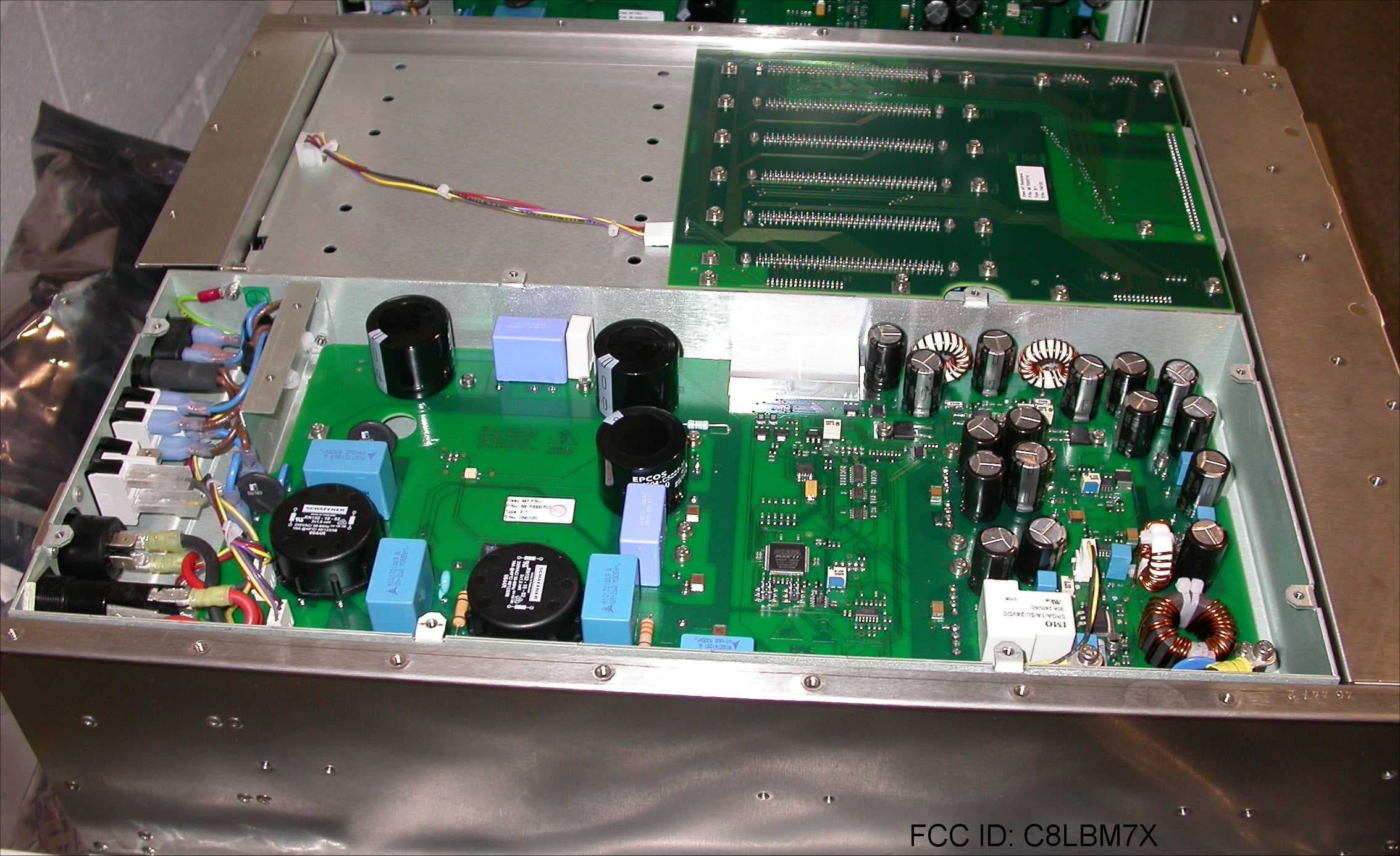
C8LBM7X
Feb 03, 200850W Transceiver
Equipment Class
TNB - Licensed Non-Broadcast Station Transmitter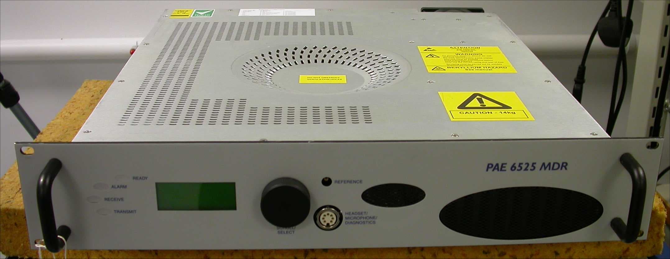
C8LB6525MDR
Aug 01, 2007Multimode VHF Ground to Air Transceiver
Equipment Class
TNB - Licensed Non-Broadcast Station Transmitter
C8LB63300HS
Jun 06, 2007VHF Ground to Air Transmitter
Equipment Class
TNB - Licensed Non-Broadcast Station Transmitter
C8LB6350-S2
Oct 02, 2005VHF ground to air transmitter
Equipment Class
TNB - Licensed Non-Broadcast Station Transmitter
C8LB6100-S2
Oct 02, 2005VHF fixed ground based aeronautical receiver
Equipment Class
CXX - Communications Rcvr for use w/ licensed Tx and CBs