C8LB63100HSVHF Ground to air transmitter
Park Air Systems Limited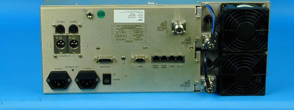
Click to zoom
Application Details
- Equipment Class
- TNB - Licensed Non-Broadcast Station Transmitter
- Date of Grant
- Jul 07, 2005
- Application Purpose
- Original Equipment
- Date of Application
- Jul 07, 2005
- Equipment Note
- VHF Ground to air transmitter
- Frequency Range
- 118.00000000 - 136.97500000
- Company
- Park Air Systems Limited
- Country
- United Kingdom
Documents & Files
Document Text
Text extracted from the exhibit documents filed with the FCC. Open a document above to read the original.
Users Manual
T6T VHF 100 W Transmitter User Documentation Page iiT6T VHF 100 W Transmitter Handbook Title:T6T VHF 100 W Transmitter User Documentation Handbook Part Number:31-3T6T100V Handbook Version:2.0 Date of Issue:February 2005 Equipment Modification Level7 Published By:Park Air Systems Northfields Market Deeping Peterborough PE6 8UE England Telephone:From UK, 01778 345434 From outside UK, 44 1778 345434 Fax:From UK, 01778 342877 From outside UK, 44 1778 342877 www.parkairsystems.com Errata Any errors found in this handbook are promulgated through the Park Air FTP network. Any user can access this information by logging on to: ftp.parkairsystems.com When logged on, select the public (Pub) folder, then the Handbook Errata Sheets folder, and then select the required equipment model. [Adobe Acrobat™ must be loaded on your PC to use this facility] T6T VHF 100 W TransmitterPage iii Health and Safety Warnings A warning is used to indicate possible danger to personnel. Throughout Park Air handbooks, warnings are indicated by the following symbols: Cautions A caution is used to indicate possible danger to the equipment. Trademarks The following tradenames are used in this handbook. IBMThis is a registered trademark of International Business Machines. MicrosoftThis is a registered trademark of Microsoft Corporation in the USA and other countries. WindowsThis is a registered trademark of Microsoft Corporation in the USA and other countries. Indicates electrical danger to personnel.WARNING Indicates a hazardous material. WARNING Indicates a non-ionizing radiation hazard. WARNING Indicates a specified danger to personnel. WARNING Indicates the presence of electrostatic sensitive devices (ESSD). Caution Indicates a specified danger to the equipment. Caution Page ivT6T VHF 100 W Transmitter List of Abbreviations acalternating current AGCautomatic gain control AMamplitude modulation ATCair traffic control BERbit error rate BITbuilt-in test Ccelsius CDcompact disk dBdecibel dcdirect current DSBdouble sideband E-BITexternal bit signal ESSDelectrostatic sensitive devices Figfigure FMfrequency modulation Hzhertz IFintermediate frequency kgkilogramme kHzkilohertz LCDliquid crystal display mmetre mAmilliamp MARCmulti-access remote control mmmillimetre mWmilliwatt MHzmegahertz MSKminimum shift keying PApower amplifier PCpersonal computer PCBprinted circuit board pk-pkpeak-to-peak ppmparts per million PSUpower supply unit PTTpress to transmit RFradio frequency ROMread-only memory RSE2remote site equipment RSSIreceiver signal strength indication Vvolt VFPvirtual front panel VHFvery high frequency VOGADvoice-operated gain adjusting device VSWRvoltage standing wave ratio Wwatt Approvals and Standards T6T VHF 100 Watt Transmitters Approvals: The equipment is designed to meet the essential requirements of Directives 1999/5/EC, 89/336EEC as amended by Directive 93/68/EEC, and 72/23/EEC. Standards: The following standards are applied: EMC EN 301 489-1; EN 301 489-22. Health & Safety, EN 60950, CAN/CSA-C22.2 No. 60950, UL 60950. Radio EN 300 676, IC RSS141, FCC part 15 and 87. Telecom CS-03. FCC Statement: This device has been tested and found to comply with the limits for a Class B digital device, pursuant to part 15 of the FCC Rules. These limits are designed to provide reasonable protection against harmful interference in a residential installation. This equipment generates, uses and can radiate radio frequency energy and, if not installed and used in accordance with the instructions, may cause harmful interference to radio communications. However, there is no guarantee that interference will not occur in a particular installation. If this equipment does cause harmful interference to radio or television reception, which can be determined by turning the equipment off and on, the user is encouraged to try to correct the interference by one or more of the following measures: -Reorient or relocate the receiving antenna. -Increase the separation between the equipment and the receiver. -Connect the equipment into an outlet on a circuit different from that to which the receiver is connected. -Consult the supplier or an experienced radio/TV technician for help. Operation on 8.33 kHz channel spacing is restricted to European customers. Page viT6T VHF 100 W Transmitter About This Hard Copy This document, apart from the preface, is a hard copy of the files contained on the CD and comprises the following parts: Preface (not on CD) Introduction Specification Operation Installation Maintenance. Back to Transmitter Main Page Introduction This topic gives a brief introduction to the T6T VHF 100 W Multimode Transmitter. T6T VHF 100 W TransmitterPage 2Introduction Back to Transmitter Main Page Purpose The T6T VHF multimode 100 W transmitter is intended for use in fixed ground environments such as airports and en-route centres. The transmitter operates in voice and ICAO defined data modes at frequencies between 118 and 136.975 MHz. Dependent on the software loaded into the radio, the following operating modes can be selected: ❑AM-Voice. All transmitters have this mode ❑AM-MSK (optional) ❑Mode 2 (optional) ❑Mode 3 (optional). Fig 1 T6T VHF 100 W Transmitter Models and Part Numbers The following table identifies the T6T VHF 100 W transmitters: Mechanical Installation The transmitter fits into an industrial standard 19 inch (483 mm) equipment cabinet and occupies 4U of space. DescriptionPart NumberFrequency RangeChannel Spacing (AM-Voice) Special Applications T6T 100 W standard frequency coverage high stability transmitter B63100HS/NB118 to 136.975 MHz25 kHz or 8.33 kHz Supports 5-offset carrier operation T6T VHF 100 W TransmitterPage 3Introduction Back to Transmitter Main Page Frequency Selection T6 radios operate with 8.33 kHz and 25 kHz channel spacing. The radios recognize frequencies entered in ICAO format and automatically adjust to the correct channel spacing. For multichannel operation up to 100 preset frequency channels can be stored i…
Text truncated - open the document above for the full version.
Cover Letter(s)
1 March 2005 BABT 34 Molesey Road Walton on Thames Surrey KT12 4RQ Re: Request of Confidentiality Pursuant to Sections 0.457(d)(1)(ii) and 0.459 of the Commission’s Rules, the Applicant hereby requests confidential treatment of information accompanying as outlined below: Schematics, Technical Description, & Bill of Materials . The above materials contain trade secrets and proprietary information not customarily released to the public. The public disclosure of these matters might be harmful to the Applicant and provide unjustified benefits to its competitors. The Applicant understands that pursuant to Rule 0.457(d)(1)(ii), disclosure of this Application and all accompanying documentation will not be made before the date of the Grant for this Application. Sincerely, Allan Horsfield Consultant Engineer EMC & Approvals Telephone Number 01778 34534 Fax Number 01778 381587 Email [email protected] Park Air Systems Ltd, Northfields, Market Deeping, Peterborough, PE6 8UE, England. Tel: +44 1778 345434 Fax: +44 1778 342877 www.parkairsystems.com Registered in England 1951792 A subsidiary of Northrop Grumman Corporation VAT No: 551 086 749
Cover Letter(s)
Product: 100W VHF ground to air communications transmitter Type Designation: T6T HS 100, Model Number B63100HS We authorise TUV Product Service Ltd, Segensworth Road, Fareham, PO15 5RH / Octagon House Concorde Way Segensworth North PO15 5RL to act on our behalf on all certification matters concerning the above named equipment. This shall include the following: a) Certification application and procedures b) Payment of approval fees We declare that TUV Product Service Ltd is allowed to forward all information related to the approval project to Industry Canada & the FCC and discuss any issues concerning the applications for certification. On behalf of Park Air Systems Limited. Mr. Allan Horsfield Date: 4 March 2005 Consultant Engineer. Location: Market Deeping Park Air Systems Ltd, Northfields, Market Deeping, Peterborough, PE6 8UE, England. Tel: +44 1778 345434 Fax: +44 1778 342877 www.parkairsystems.com Registered in England 1951792 A subsidiary of Northrop Grumman Corporation VAT No: 551 086 749
Cover Letter(s)
1 April 2005 FAA Spectrum Engineering Division 800 Independence Avenue SW Washington, DC 20591 Dear Sirs, Please be advised that we are making applications to the Federal Communications Commission to obtain Equipment Authorisation grants for Park Air Systems new range of VHF multimode transmitters and receiver type T6. The models covered are : T6T 50W VHF AM transmitter under filing C8LB6350/S2 T6TR 50W VHF AM transceiver under filing C8LB6550/S2 T6R VHF AM receiver under filing C8LB6100/S2 T6T HS 100 VHF 100W AM transmitter under filing C8LB63100HS The equipment provides upto 50W/100W RF output power in the 118 – 136.975 MHz band employing A3E (AM) modulation. The original versions of of the 50W T6 transmitter and receiver were filed in 2000. The new models have been redesigned to use more common modules and improve compatibility with future digital modes. A summary of the equipment’s performance is attached. Our application to the FCC is being made via TuV Product Service in the UK, acting as our Conformity Assessment Body. If you could address any concerns or objections to myself or TuV I would be grateful. Yours faithfully, Allan Horsfield Principal Engineer EMC and Approvals CAB: TUV Product Service Ltd, Segensworth Road, Fareham, Hampshire PO15 5RH England Attention: Maggie Glasspool [email protected] Park Air Systems Ltd, Northfields, Market Deeping, Peterborough, PE6 8UE, England. Tel: +44 1778 345434 Fax: +44 1778 342877 www.parkairsystems.com Registered in England 1951792 A subsidiary of Northrop Grumman Corporation FAA Notification of FCC Type Acceptance Application for T6 Series. General FCC Number T6T 50W VHF transmitter C8LB6350/S2 T6TR 50W VHF transceiver C8LB6550/S2 T6T HS 100 A 100W variant of the T6T HS C8LB63100HS T6R VHF receiver C8LB6100/S2 Manufacturer Park Air Systems Ltd. England. RF Output Power 50 Watts (100 Watts for T6T HS 100) Antenna port 50R N-type connector Frequency range 118 MHz to 136.975 MHz. Method of tuning Frequency selected by front panel control and LCD display. Channelling capability 25 kHz (8.33kHz capable). Emission bandwidth Within FCC limits see attached report summary Emission type 6K00A3E Emission/harmonics See attached report summary EMC All products are Type examined under the EMC Directive to comply with emission and immunity requirements to Class B. Certificates attached. Description Park Air Systems T6 series are VHF multi-mode air-traffic control radios compatible with analogue (AM) and digital (D8PSK) modulation modes. Current models are supplied programmed for AM voice operation in the frequency range 118 to 136.975 MHz using 25 kHz or 8.33 kHz channel spacing. The latter is disabled through front panel settings for the American market. The transmitter produces a 50W/100W carrier output that can be reduced, in steps, to 5/10W. The output power, and the majority of operational settings, can be selected at the front panel, using the virtual front panel (VFP) on a pc, or through a compatible control and data system such as the PAE multi-access remote control (MARC) system. A multi-channel feature allows up to 100 frequency channels to be stored and recalled by channel number. The T6R is the complementary receiver utilising the same front panel and processor modules to minimise spares requirements. The equipment is designed to be fitted in an industrial 19 inch (483 mm) equipment rack. Operation is from either a standard ac mains supply, or from a low voltage dc supply. When both input supplies are connected, the dc supply acts as a back-up if the mains supply fails. Comprehensive continuous and interruptive Built-In Tests (BIT) provide confidence of the radios serviceability. All transmitters employ the same processor control module, power amplifiers and power supplies. The T6TR power amplifier is identical to the T6T but has a PIN diode antenna changeover device fitted. The 100W version uses two combined 50W power amplifiers. T6 Series transmitter emission performance summary: All results taken from report number OR613603/02 (T6T) OR613603/03 (T6TR) & OR613878/01 (T6 HS 100) produced by TuV Product Service* for our applications for Grant of Equipment Authorisation. Occupied Bandwidth - 47 CFR 2.1049 (1) From Report OR613603/02 T6T From Report OR613603/03 T6TR From Report OR613878/01 T6T HS 100 * FCC Registration Number 90987 T6T T6TR T6T HS 100 Spurious emissions at antenna terminals - 47 CFR 2.1051 Results in accordance with Part 2.1051 and 87.139 Emission Limits Note: Emissions 20dB below limit are not required to be listed Carrier Frequency (Fc) : 127.5 MHz Transmitting From Report OR613603/02 T6T From Report OR613603/03 T6TR From Report OR613878/01 T6T HS 100 Field Strength of Spurious radiation - 47 CFR 2.1053 Carrier Frequency (Fc) : 118 MHz (T6T/TR) Absolute Level Level (relative to RF Power 50W) dB w.r.t limit of 43+10 log power Frequency (MHz) Identity dBm dBc Remarks limit - 13 limit - 60 236.00 2Fc --26.68 -73.68 354.00 3Fc -27.67 -74.67 All others greater than 20dB within Specification Limit. From Report OR613878/01 T6T HS 100 Carrier Frequency (Fc) : 118 MHz Absolute Level Level (relative to RF Power 50W) dB w.r.t limit of 43+10 log power Frequency (MHz) Identity dBm dBc Remarks limit - 13 limit - 63 200.8 spur -24.83 -74.83 236.00 2Fc --22.45 -72.45 354.00 3Fc -42.33 -92.33 All others greater than 20dB within Specification Limit. UK EMC Type Certification Equipment Photos T6T HS 100 T6T HS 100 Rear panel. Note all interface connections are common across the range.
External Photos
FCC ID: C8LB63100HS PARK AIR SYSTEMS T6T 100W VHF Transmitter ©2005 Not to be reproduced without the permission of TÜV Product Service Ltd Page 1 of 4 PHOTOGRAPHS OF EQUIPMENT Front /Top View FCC ID: C8LB63100HS PARK AIR SYSTEMS T6T 100W VHF Transmitter ©2005 Not to be reproduced without the Permission of TÜV Product Service Ltd Page 2 of 4 PHOTOGRAPHS OF EQUIPMENT Right Hand Side View FCC ID: C8LB63100HS PARK AIR SYSTEMS T6T 100W VHF Transmitter ©2005 Not to be reproduced without the Permission of TÜV Product Service Ltd Page 3 of 4 PHOTOGRAPHS OF EQUIPMENT Base/Rear View FCC ID: C8LB63100HS PARK AIR SYSTEMS T6T 100W VHF Transmitter ©2005 Not to be reproduced without the Permission of TÜV Product Service Ltd Page 4 of 4 PHOTOGRAPHS OF EQUIPMENT Left Hand Side View
ID Label/Location Info
LO613878 Park Air Systems T6T HS 100 Park Air Systems T6T HS 100 Example label and label position
ID Label/Location Info
24 March 2005 TuV Product Service Octagon House Concorde Way Segensworth North Fareham Hampshire PO15 5RL Reference FCC Filing for T6T 100 HS Dear Sirs, Regarding our applications for FCC certification on the above product please be advised that the model T6T 100HS (C8LB63100HS) will have the following Part 15 label attached: This device complies with Part 15 of the FCC Rules. Operation is subject to the following two conditions: (1) This device may not cause harmful interference, and (2) this device must accept any interference received, including interference that may cause undesired operation. Yours sincerely, Allan Horsfield Consultant Engineer EMC and Approvals Park Air Systems Ltd, Northfields, Market Deeping, Peterborough, PE6 8UE, England. Tel: +44 1778 345434 Fax: +44 1778 342877 www.parkairsystems.com Registered in England 1951792 A subsidiary of Northrop Grumman Corporation VAT No: 551 086 749 Park Air Systems Ltd, Northfields, Market Deeping, Peterborough, PE6 8UE, England. Tel: +44 1778 345434 Fax: +44 1778 342877 www.parkairsystems.com Registered in England 1951792 A subsidiary of Northrop Grumman Corporation VAT No: 551 086 749
Internal Photos
FCC ID: C8LB63100HS PARK AIR SYSTEMS T6T 100W VHF Transmitter ©2005 Not to be reproduced without the permission of TÜV Product Service Ltd Page 1 of 2 PHOTOGRAPHS OF EQUIPMENT Internal View 1 FCC ID: C8LB63100HS PARK AIR SYSTEMS T6T 100W VHF Transmitter ©2005 Not to be reproduced without the permission of TÜV Product Service Ltd Page 2 of 2 PHOTOGRAPHS OF EQUIPMENT Internal View 2
Operational Description
T6T VHF 100 W Transmitter User Documentation Page iiT6T VHF 100 W Transmitter Handbook Title:T6T VHF 100 W Transmitter User Documentation Handbook Part Number:31-3T6T100V Handbook Version:2.0 Date of Issue:February 2005 Equipment Modification Level7 Published By:Park Air Systems Northfields Market Deeping Peterborough PE6 8UE England Telephone:From UK, 01778 345434 From outside UK, 44 1778 345434 Fax:From UK, 01778 342877 From outside UK, 44 1778 342877 www.parkairsystems.com Errata Any errors found in this handbook are promulgated through the Park Air FTP network. Any user can access this information by logging on to: ftp.parkairsystems.com When logged on, select the public (Pub) folder, then the Handbook Errata Sheets folder, and then select the required equipment model. [Adobe Acrobat™ must be loaded on your PC to use this facility] T6T VHF 100 W TransmitterPage iii Health and Safety Warnings A warning is used to indicate possible danger to personnel. Throughout Park Air handbooks, warnings are indicated by the following symbols: Cautions A caution is used to indicate possible danger to the equipment. Trademarks The following tradenames are used in this handbook. IBMThis is a registered trademark of International Business Machines. MicrosoftThis is a registered trademark of Microsoft Corporation in the USA and other countries. WindowsThis is a registered trademark of Microsoft Corporation in the USA and other countries. Indicates electrical danger to personnel.WARNING Indicates a hazardous material. WARNING Indicates a non-ionizing radiation hazard. WARNING Indicates a specified danger to personnel. WARNING Indicates the presence of electrostatic sensitive devices (ESSD). Caution Indicates a specified danger to the equipment. Caution Page ivT6T VHF 100 W Transmitter List of Abbreviations acalternating current AGCautomatic gain control AMamplitude modulation ATCair traffic control BERbit error rate BITbuilt-in test Ccelsius CDcompact disk dBdecibel dcdirect current DSBdouble sideband E-BITexternal bit signal ESSDelectrostatic sensitive devices Figfigure FMfrequency modulation Hzhertz IFintermediate frequency kgkilogramme kHzkilohertz LCDliquid crystal display mmetre mAmilliamp MARCmulti-access remote control mmmillimetre mWmilliwatt MHzmegahertz MSKminimum shift keying PApower amplifier PCpersonal computer PCBprinted circuit board pk-pkpeak-to-peak ppmparts per million PSUpower supply unit PTTpress to transmit RFradio frequency ROMread-only memory RSE2remote site equipment RSSIreceiver signal strength indication Vvolt VFPvirtual front panel VHFvery high frequency VOGADvoice-operated gain adjusting device VSWRvoltage standing wave ratio Wwatt Approvals and Standards T6T VHF 100 Watt Transmitters Approvals: The equipment is designed to meet the essential requirements of Directives 1999/5/EC, 89/336EEC as amended by Directive 93/68/EEC, and 72/23/EEC. Standards: The following standards are applied: EMC EN 301 489-1; EN 301 489-22. Health & Safety, EN 60950, CAN/CSA-C22.2 No. 60950, UL 60950. Radio EN 300 676, IC RSS141, FCC part 15 and 87. Telecom CS-03. FCC Statement: This device has been tested and found to comply with the limits for a Class B digital device, pursuant to part 15 of the FCC Rules. These limits are designed to provide reasonable protection against harmful interference in a residential installation. This equipment generates, uses and can radiate radio frequency energy and, if not installed and used in accordance with the instructions, may cause harmful interference to radio communications. However, there is no guarantee that interference will not occur in a particular installation. If this equipment does cause harmful interference to radio or television reception, which can be determined by turning the equipment off and on, the user is encouraged to try to correct the interference by one or more of the following measures: -Reorient or relocate the receiving antenna. -Increase the separation between the equipment and the receiver. -Connect the equipment into an outlet on a circuit different from that to which the receiver is connected. -Consult the supplier or an experienced radio/TV technician for help. Operation on 8.33 kHz channel spacing is restricted to European customers. Page viT6T VHF 100 W Transmitter About This Hard Copy This document, apart from the preface, is a hard copy of the files contained on the CD and comprises the following parts: Preface (not on CD) Introduction Specification Operation Installation Maintenance. Back to Transmitter Main Page Introduction This topic gives a brief introduction to the T6T VHF 100 W Multimode Transmitter. T6T VHF 100 W TransmitterPage 2Introduction Back to Transmitter Main Page Purpose The T6T VHF multimode 100 W transmitter is intended for use in fixed ground environments such as airports and en-route centres. The transmitter operates in voice and ICAO defined data modes at frequencies between 118 and 136.975 MHz. Dependent on the software loaded into the radio, the following operating modes can be selected: ❑AM-Voice. All transmitters have this mode ❑AM-MSK (optional) ❑Mode 2 (optional) ❑Mode 3 (optional). Fig 1 T6T VHF 100 W Transmitter Models and Part Numbers The following table identifies the T6T VHF 100 W transmitters: Mechanical Installation The transmitter fits into an industrial standard 19 inch (483 mm) equipment cabinet and occupies 4U of space. DescriptionPart NumberFrequency RangeChannel Spacing (AM-Voice) Special Applications T6T 100 W standard frequency coverage high stability transmitter B63100HS/NB118 to 136.975 MHz25 kHz or 8.33 kHz Supports 5-offset carrier operation T6T VHF 100 W TransmitterPage 3Introduction Back to Transmitter Main Page Frequency Selection T6 radios operate with 8.33 kHz and 25 kHz channel spacing. The radios recognize frequencies entered in ICAO format and automatically adjust to the correct channel spacing. For multichannel operation up to 100 preset frequency channels can be stored i…
Text truncated - open the document above for the full version.
Parts List/Tune Up Info
Wednesday, 24 March 2005 TuV Product Service Octagon House Concorde Way Segensworth North Fareham Hampshire PO15 5RL Reference FCC Filings for T6T 100HS (C8LB63100HS), Dear Sirs, Regardi ng our application for FCC certification on the above product please be advised that there are no user tuneable parts on the equipment. Yours sincerely, Allan Horsfield Consultant Engineer EMC and Approvals - Park Air Systems Ltd, Northfields, Market Deeping, Peterborough, PE6 8UE, England. Tel: +44 1778 345434 Fax: +44 1778 342877 www.parkairsystems.com Registered in England 1951792 A subsidiary of Northrop Grumman Corporation VAT No: 551 086 749
Test Report
REPORT ON FCC CFR 47: Part 15 (Subparts B & C) and Part 87 Testing in support of an Application for Grant of Equipment Authorisation of a Park Air Systems T6T 100W VHF Transmitter FCC ID: C8LB63100HS Report No OR613878/01 Issue 2 July 2005 Competence. Certainty. Quality COMMERCIAL-IN-CONFIDENCE TUV Product Service Ltd, Octagon House, Concorde Way, Segensworth North, Fareham, Hampshire, United Kingdom, PO15 5RL Tel: +44 (0) 1489 558100. Website: www.tuvps.co.uk ; www.babt.com Report No OR613878/01 Issue 2 Page 1 of 48 COMMERCIAL-IN-CONFIDENCE REPORT ON FCC CFR 47: Part 15 (Subparts B & C) and Part 87 Testing in support of an Application for Grant of Equipment Authorisation of a Park Air Systems T6T 100W VHF Transmitter FCC ID: C8LB63100HS Report No OR613878/01 Issue 2 July 2005 PREPARED FOR Park Air Systems Limited Northfields Ind Estate Market Deeping Peterborough PE6 8UE United Kingdom PREPARED BY M Glasspool Project Manager APPROVED BY K Adsetts M Jenkins UKAS Signatory UKAS Signatory DATED 4 th July 2005 DISTRIBUTION Park Air Systems Limited Copy 1 TUV Product Service Ltd Copy 2 Copy No ENGINEERING STATEMENT The measurements shown in this report were made in accordance with the procedures described on test pages. All reported testing was carried out on a sample equipment to demonstrate limited compliance with FCC CFR 47: Parts 87 & 15 Subparts B & C. The sample tested was found to comply with the requirements defined in the applied rules. Test Engineers; S Hartley B Airs G Lawler S Bennett FCC ID: C8LB63100HS COMMERCIAL-IN-CONFIDENCE Report No OR613878/01 Issue 2 Page 2 of 48 COMMERCIAL-IN-CONFIDENCE CONTENTS Section Page No 1 REPORT SUMMARY 1.1 Status.................................................................................................................................. 4 1.2 Introduction ......................................................................................................................... 5 1.3 Brief Summary of Results................................................................................................... 6 1.4 Product information............................................................................................................ 7 1.5 Test Conditions (Configuration).......................................................................................... 7 1.6 Deviations from the Standard............................................................................................. 7 1.7 Modification Record............................................................................................................ 7 1.8 Alternative Test Site ........................................................................................................... 7 2 TEST DETAILS 2.1 Spurious Radiated Emissions: Part 15.209........................................................................ 9 2.2 Conducted Emissions On Power Lines: Part 15.207......................................................... 12 2.3 Spurious Radiated Emissions: Part 87.139........................................................................ 17 2.4 Occupied Bandwidth Of Transmitter: Section 2.1049(c)(1)/ Parts 87.135 & 87.137. ........ 20 2.5 Modulation Characteristics Of The Transmitter: Section 2.1047/ Part 87.141................... 24 2.6 Frequency Stability: Part 87.133 (a) ................................................................................... 30 2.7 Transmitter Output Power: Part 87.131 .............................................................................. 32 2.8 Transmitter Unwanted Emissions: Part 87.139 (a) ............................................................. 33 3 TEST EQUIPMENT USED 3.1 Table of Test Equipment Used ........................................................................................... 44 3.2 Measurement Uncertainty .................................................................................................. 46 4 ACCREDITATION, DISCLAIMERS AND COPYRIGHT 4.1 Accreditation, Disclaimers and Copyright.................................................................................. 48 APPENDICES A Titchfield FCC Site Compliance Letter .....................................................................................A.2 FCC ID: C8LB63100HS COMMERCIAL-IN-CONFIDENCE Report No OR613878/01 Issue 2 Page 3 of 48 COMMERCIAL-IN-CONFIDENCE SECTION 1 REPORT SUMMARY FCC CFR 47: Parts 15 Subparts B & C and Part 87 Testing in support of an Application for Grant of Equipment Authorisation of a Park Air Systems T6T 100W VHF Transmitter FCC ID: C8LB63100HS COMMERCIAL-IN-CONFIDENCE Report No OR613878/01 Issue 2 Page 4 of 48 COMMERCIAL-IN-CONFIDENCE 1.1 STATUS EQUIPMENT UNDER TEST Park Air Systems T6R VHF Transmitter OBJECTIVE To undertake measurements to determine the Equipment Under Test's (EUT's) compliance with the specification. NAME AND ADDRESS OF CLIENT Park Air Systems Limited Northfields Ind Estate Market Deeping Peterborough PE6 8UE United Kingdom TYPE / MODEL NUMBER T6T HS 100 SERIAL NUMBER 2K5008 DECLARED VARIANTS None TEST SPECIFICATION / ISSUE / DATE FCC CFR 47; Part 15, Subparts B & C: 2003 FCC CFR 47; Part 87: 2004 NUMBER OF ITEMS TESTED One SECURITY CLASSIFICATION OF EUT Commercial In Confidence INCOMING RELEASE Declaration of Build Status DATE 22 February 2005 DISPOSAL Packing Note REFERENCE NUMBER OR613878-01 DATE 7 March 2005 ORDER NUMBER BPE14519 Ref Allan Horsfield DATE 23 February 2005 START OF TEST 28 February 2005 FINISH OF TEST 22 June 2005 RELATED DOCUMENTS ANSI C63.4: 2001. Methods of Measurement of Radio- Noise Emissions from Low-Voltage Electrical and Electronic Equipment in the Range of 9 kHz to 40 GHz. FCC Part 2.1053: 2003 FCC ID: C8LB63100HS COMMERCIAL-IN-CONFIDENCE Report No OR613878/01 Issue 2 Page 5 of 48 COMMERCIAL-IN-CONFIDENCE 1.2 INTRODUCTION The information contained within this report is intended to show limited verification of compliance of the Park Air Systems T6T 100W VHF Transmitter to …
Text truncated - open the document above for the full version.
Contact Information
Applicant
Philip Ackerman(Consultant Engineer)
Test Firm
TUV SUD Product ServiceJensen Adams
Technical Specifications
| # | Rule Parts | Frequency Range | Power Output | Emission | Tolerance |
|---|---|---|---|---|---|
| 1 | 87 | 118 MHz - 136.975 MHz | 100 W | 6K00A3E | 1.0000000000 ppm |
Other Applications from Park Air Systems Limited
C8LBM7X
Feb 03, 200850W Transceiver
Equipment Class
TNB - Licensed Non-Broadcast Station Transmitter
C8LB6525MDR
Aug 01, 2007Multimode VHF Ground to Air Transceiver
Equipment Class
TNB - Licensed Non-Broadcast Station Transmitter
C8LB63300HS
Jun 06, 2007VHF Ground to Air Transmitter
Equipment Class
TNB - Licensed Non-Broadcast Station Transmitter
C8LB6350-S2
Oct 02, 2005VHF ground to air transmitter
Equipment Class
TNB - Licensed Non-Broadcast Station Transmitter
C8LB6100-S2
Oct 02, 2005VHF fixed ground based aeronautical receiver
Equipment Class
CXX - Communications Rcvr for use w/ licensed Tx and CBs