C8LB6550-S2VHF ground to air transceiver
Park Air Systems Limited
Click to zoom
Application Details
- Equipment Class
- TNB - Licensed Non-Broadcast Station Transmitter
- Date of Grant
- Sep 29, 2005
- Application Purpose
- Original Equipment
- Date of Application
- Sep 29, 2005
- Equipment Note
- VHF ground to air transceiver
- Frequency Range
- 112.00000000 - 155.97500000
- Company
- Park Air Systems Limited
- Country
- United Kingdom
Documents & Files
Document Text
Text extracted from the exhibit documents filed with the FCC. Open a document above to read the original.
Users Manual
T6TR 50 Watt VHF Multimode Transceiver Select Topic Back to Main Page Maintenance Installation Operation Specification This documentation is applicable to transceivers at Mod strike 7 Approvals and Standards Back to Transceiver Main Page Approvals and Standards T6TR VHF 50 Watt Transceivers The following standards are applied: EMC EN 301 489-1; EN 301 489-22. Health & Safety, EN 60950, CAN/CSA-C22.2 No. 60950, UL 60950. Radio EN 300 676, IC RSS141, FCC part 15 and 87. Telecom CS-03. Approvals: Standards: The equipment is designed to meet the essential requirements of Directives 1999/5/EC, 89/336EEC as amended by Directive 93/68/EEC, and 72/23/EEC. FCC Statement: This device has been tested and found to comply with the limits for a Class B digital device, pursuant to part 15 of the FCC Rules. These limits are designed to provide reasonable protection against harmful interference in a residential installation. This equipment generates, uses and can radiate radio frequency energy and, if not installed and used in accordance with the instructions, may cause harmful interference to radio communications. However, there is no guarantee that interference will not occur in a particular installation. If this equipment does cause harmful interference to radio or television reception, which can be determined by turning the equipment off and on, the user is encouraged to try to correct the interference by one or more of the following measures: ❑Reorient or relocate the receiving antenna. ❑Increase the separation between the equipment and the receiver. ❑Connect the equipment into an outlet on a circuit different from that to which the receiver is connected. ❑Consult the supplier or an experienced radio/TV technician for help. Operation on 8.33 kHz channel spacing is restricted to European customers. Page 1 Back to Transceiver Main Page Specification Part 1 General Specification Part 2 AM Modes Part 3 Mode 2 Part 4 Mode 3 This document provides specifications applicable to the T6TR VHF Multimode Transceiver. Page 2 Back to Transceiver Main Page General Specification The general specification applies to a transceiver irrespective of the selected operating mode. Separate listings are given for AM modes, Mode 2 and Mode 3. Frequency Range The T6TR VHF Multimode Transceiver is available in two variants as listed below: ❑The B6550/NB/50 that operates within the frequency band 118 to 136.975 MHz. ❑The B65500/WB/50 that operates within the frequency band 112 to 155.975 MHz. Frequency Selectable Band Edges Four selectable frequency band edges are available on each model: BE1, BE2, BE3 and BE4. Frequencies can only be selected that lie between BE1 and BE2 inclusive or between BE3 and BE4 inclusive. The band edge frequencies can only be set in 25 kHz increments. BE1 and BE3 both default to the lowest selectable frequency for the model and BE2 and BE4 both default to the highest selectable frequency for the model. Frequency Accuracy Better than 1ppm. Reference Frequency Adjustment Provision is made on the front panel to allow the 20.95 MHz reference oscillator frequency to be adjusted. An output is provided suitable for driving an external frequency counter. Adjustment allows the frequency to be set to within 0.15 ppm. Frequency Change Time Less than 250 ms from receipt of a remote frequency change command message. Number of Channels The transceiver has a multi-channel capability. 100 channels can be stored and recalled. Modulation Modes AM-Voice (standard). AM-MSK (optional). Mode 2 (optional). Mode 3 (optional). Page 3 Back to Transceiver Main Page Power Requirements The transceiver operates from an ac mains supply, or a dc input supply. When both supplies are connected, the dc input acts as an automatic backup for the ac mains. ac input supplyThe transceiver operates from a 48 to 62 Hz single-phase ac supply and automatically adjusts to operate from any supply voltage ranging from 110 Vac to 240 Vac ±10%. The power consumption figures are given in Table 1. dc input supplyThe transceiver operates from a dc input supply between 21.6 and 32 V (measured at the radio’s input). The supply current figures are given in Table 1. Dimensions and Weight The dimensions and weight of the transceiver are: Width483 mm (19 inches). Height88.9 mm (3.5 inches). The height occupies 2U of equipment cabinet space. Depth 430 mm (16.9 inches) measured from front panel to rear panel. Depth 450 mm (17.8 inches) measured from front panel to rear of fan. Weight13.5 kg (29.76 pounds). Environmental Temperature rangeThe transceiver operates to specification across the temperature range of -20 to +55°C. The transceiver can be stored at temperatures ranging from -30 to +70°C without causing any damage. HumidityThe transceiver operates to specification at a relative humidity between 5% and 90% non-condensing. AltitudeThe radios operate to specification up to 15,000 feet. Additionally the equipment is capable of storage at altitudes up to 50,000 feet without damage. Shock and vibrationThe radios comply with shock and vibration protection MIL-STD-810E, method 516.4, procedure VI - Bench Handling. In all cases, no fixed parts become loose. No movable part or permanently set adjustment shifts its setting or position. Table 1 Power Consumption Transmitting or Receiving RequirementNormal Operation acdc TransmittingTypical300 VA8.5 A Maximum500 VA12 A ReceivingTypical70 VA1.2 A Page 4 Back to Transceiver Main Page VentilationThe transceivers are cooled by an integral fan, which normally runs at half speed. At an RF PA temperature of 45°C this is increased to full speed and at 40°C it reduces to half speed again. The transceivers also include an additional temperature controlled fan contained in the power supply. Warm up timeAll variants are fully operational to specification within 20 seconds after switch on. Page 5 Back to Transceiver Main Page AM Modes Introduction The transceiver can operate in AM-Voice mode and AM-MSK mode. The following specifi…
Text truncated - open the document above for the full version.
Users Manual
PAE T6TR PAE T6TR TRANSCEIVER, VHF Multimode Digital Radio (MDR) •VHF 118 to 144 MHz Multimode Digital Radio (MDR) •8.33 kHz and 25 kHz channel spacing •50 W RF output power •Digital Coherent Mute (DCM) technology •Compact 2U case •Analogue and digital operation •Extensive remote control facilities TECHNICAL INFORMATION PAE T6TR TRANSCEIVER, VHF Multimode Digital Radio (MDR) Park Air Systems reserves the right to amend specifications in the light of continuing development - 042-2 A subsidiary of Northrop Grumman Corporation GENERAL Frequency range:118 to 136.975 MHz Option 1118 to 143.975 MHz Channel spacing - AM8.33 kHz and 25 kHz Modes:A3E AM-voice OptionsAM-MSK VDL-2 VDL-3 Supported standardsICAO Annex 10 EN 301 841-1 EN 300 676 Frequency stability <1 ppm Ref oscillator adjustFrom front panel rotary encoder Duty cycle100% continuous transmit Operating temperature-20 to +55°C Storage temperature-30 to +70°C Housing:19” cabinet OptionDesk mount Power consumption: ac dc Transmit330 VA 10 A Receive70 VA 1.4 A Standby45 VA 0.5 A Supplyac: 99 to 264 V 48 to 62 Hz dc: 21.6 to 32 V RECEIVE RF Sensitivity-107 dBm for 10 dB (S+N)/N Selectivity: 8.33 kHz<6 dB at ±3.5 kHz >70 dB at ±8.33 kHz >80 dB at ±25 kHz 25 kHz<6 dB at ±11 kHz >80 dB at ±25 kHz SquelchThreshold adjustable in 1 dB steps for RF input levels from –114 dBm to –60 dBm (<6 to >30 dB (S+N)/N). Incorporates Digital Coherent Mute (DCM) technology to dynamically filter on-channel interference. DCM automatically mitigates co-location interference to ensure the squelch opens whenever an input signal exceeds the set threshold and has a positive (S+N)/N ratio AGC RF<3 dB change in audio output for RF signals between –107 dBm and +10 dBm AGC audio<1 dB change in audio output for modulation depth change between 90% and 30%. Automatically maintains audio at the 90% modulation equivalent level for maximum fidelity Antenna radiation<-73 dBm TRANSMIT RF Carrier power5 to 50 W in 1 W steps Modulation 0 to 100% in 1% steps VSWR mismatchFull power into VSWR of 2.5:1 Infinite VSWR without damage Harmonic outputs<-36 dBm Spurious outputs<-46 dBm VOGAD<10% change in modulation depth for 30 dB change in input level Tx mute5 dB below VOGAD threshold Time outOff, or 2 s to 510 s in 2 s steps AUDIO CHARACTERISTICS Audio distortion<5% THD Audio bandwidth: 8.33 kHz350 Hz to 2500 Hz 25 kHz300 Hz to 3400 Hz Audio interface: Line output-30 dBm to +10 dBm in 1 dB steps Line input-40 dBm to 0 dBm in 1 dB steps Loudspeaker1 W External speaker3 Vac peak-to-peak Tape-10 dBm MECHANICAL Dimensions (mm)89(H) x 483(W) x 450(D) Weight14.5 kg RF connectorsN-type sockets ORDERING INFORMATION T6TRPart No. B6550 Option 1(extended frequency range) Part No. 6550OPT1 Desk mount kitPart No. 70-6550DESK User guidePart No. 31-360000TR MicrophonePart No. 24-11030301 Headset/microphonePart No. 24-12002801 End-fed dipole antenna Part No. B2080 CONTROL Control and monitoring of the T6TR can be carried out locally from the front panel, or remotely via a RS422 serial port Pre-set channels100 Channel settingsFrequency, channel spacing, memory assignment Operation settingsIncludes mode, TX power, modulation depth, squelch defeat/level, PTT time out Installation settingsIncludes audio line levels, PTT/mute level/polarity, reference oscillator frequency Local control facilitiesRotary encoder and backlit multifunction display provide menu driven control of all transceiver operating parameters and BIT functions LED indicators for standby, ready, alarm, receive and transmit Mic/headset/diagnostic port for local operation and programming from computer via RS232 serial link Coaxial connector for monitoring reference oscillator frequency Remote control portsFacilities: Audio, control and BIT for AM operation MARC: RS422 serial port for control of radio from MARC or other compatible system HDLC: Serial interface for VDL operation T1: For connection to Remote Interface Unit for VDL operation Park Air Systems Ltd, Northfields, Market Deeping, Peterborough, England, PE6 8UE Tel: +44 1778 345434 Fax: +44 1778 342877 Email: [email protected] www.parkairsystems.com The PAE T6TR TRANSCEIVER for advanced airspace communications PAE T6TR TRANSCEIVER, VHF Multimode Digital Radio (MDR) PAET6TR The PAE T6TR TRANSCEIVER for advanced airspace communications The PAE T6TR multimode digital transceiver for ground-to-air communicationsis intended for use at low and medium density airports and air traffic control installations, emergency services and airline communications. The compact dimensions allow the T6TR to be conveniently used for both desk and rack mount operations. The radio supports both voice and ICAO defined data modes. The radio can be operated locally using the front panel controls, or remotely via flexible control interfaces. STANDBY mode allows the radio to be powered on and off remotely to ensure minimal current drain on local power supplies. A 100 channel memory allows immediate recall of stored frequencies. Frequency change can be inhibited to prevent unauthorised tuning. Both 8.33 kHz and 25 kHz channel spacing are incorporated.The T6TR recognises frequencies entered in ICAO format and automatically adjusts to the correct channel spacing. For multichannel operation, any combination of 8.33 kHz and 25 kHz channel spacing can be programmed. Careful implementation of DSP techniques significantly reduces the component count within the radio. This leads to increased reliability and reduced logistic costs. All modulation and demodulation processes are carried out using DSP algorithms that provide consistent long-term performance to further enhance equipment reliability. All adjustable parameters within the radio can be modified using the front panel controls, or from a computer connected to the headset/ diagnostics port, eliminating the need to remove equipment covers during the operational life of the radio. The use of innovative RF engineering allied to sophisticated DSP technology provides…
Text truncated - open the document above for the full version.
Cover Letter(s)
1 April 2005 FAA Spectrum Engineering Division 800 Independence Avenue SW Washington, DC 20591 Dear Sirs, Please be advised that we are making applications to the Federal Communications Commission to obtain Equipment Authorisation grants for Park Air Systems new range of VHF multimode transmitters and receiver type T6. The models covered are : T6T 50W VHF AM transmitter under filing C8LB6350/S2 T6TR 50W VHF AM transceiver under filing C8LB6550/S2 T6R VHF AM receiver under filing C8LB6100/S2 T6T HS 100 VHF 100W AM transmitter under filing C8LB63100HS The equipment provides upto 50W/100W RF output power in the 118 – 136.975 MHz band employing A3E (AM) modulation. The original versions of of the 50W T6 transmitter and receiver were filed in 2000. The new models have been redesigned to use more common modules and improve compatibility with future digital modes. A summary of the equipment’s performance is attached. Our application to the FCC is being made via TuV Product Service in the UK, acting as our Conformity Assessment Body. If you could address any concerns or objections to myself or TuV I would be grateful. Yours faithfully, Allan Horsfield Principal Engineer EMC and Approvals CAB: TUV Product Service Ltd, Segensworth Road, Fareham, Hampshire PO15 5RH England Attention: Maggie Glasspool [email protected] Park Air Systems Ltd, Northfields, Market Deeping, Peterborough, PE6 8UE, England. Tel: +44 1778 345434 Fax: +44 1778 342877 www.parkairsystems.com Registered in England 1951792 A subsidiary of Northrop Grumman Corporation FAA Notification of FCC Type Acceptance Application for T6 Series. General FCC Number T6T 50W VHF transmitter C8LB6350/S2 T6TR 50W VHF transceiver C8LB6550/S2 T6T HS 100 A 100W variant of the T6T HS C8LB63100HS T6R VHF receiver C8LB6100/S2 Manufacturer Park Air Systems Ltd. England. RF Output Power 50 Watts (100 Watts for T6T HS 100) Antenna port 50R N-type connector Frequency range 118 MHz to 136.975 MHz. Method of tuning Frequency selected by front panel control and LCD display. Channelling capability 25 kHz (8.33kHz capable). Emission bandwidth Within FCC limits see attached report summary Emission type 6K00A3E Emission/harmonics See attached report summary EMC All products are Type examined under the EMC Directive to comply with emission and immunity requirements to Class B. Certificates attached. Description Park Air Systems T6 series are VHF multi-mode air-traffic control radios compatible with analogue (AM) and digital (D8PSK) modulation modes. Current models are supplied programmed for AM voice operation in the frequency range 118 to 136.975 MHz using 25 kHz or 8.33 kHz channel spacing. The latter is disabled through front panel settings for the American market. The transmitter produces a 50W/100W carrier output that can be reduced, in steps, to 5/10W. The output power, and the majority of operational settings, can be selected at the front panel, using the virtual front panel (VFP) on a pc, or through a compatible control and data system such as the PAE multi-access remote control (MARC) system. A multi-channel feature allows up to 100 frequency channels to be stored and recalled by channel number. The T6R is the complementary receiver utilising the same front panel and processor modules to minimise spares requirements. The equipment is designed to be fitted in an industrial 19 inch (483 mm) equipment rack. Operation is from either a standard ac mains supply, or from a low voltage dc supply. When both input supplies are connected, the dc supply acts as a back-up if the mains supply fails. Comprehensive continuous and interruptive Built-In Tests (BIT) provide confidence of the radios serviceability. All transmitters employ the same processor control module, power amplifiers and power supplies. The T6TR power amplifier is identical to the T6T but has a PIN diode antenna changeover device fitted. The 100W version uses two combined 50W power amplifiers. T6 Series transmitter emission performance summary: All results taken from report number OR613603/02 (T6T) OR613603/03 (T6TR) & OR613878/01 (T6 HS 100) produced by TuV Product Service* for our applications for Grant of Equipment Authorisation. Occupied Bandwidth - 47 CFR 2.1049 (1) From Report OR613603/02 T6T From Report OR613603/03 T6TR From Report OR613878/01 T6T HS 100 * FCC Registration Number 90987 T6T T6TR T6T HS 100 Spurious emissions at antenna terminals - 47 CFR 2.1051 Results in accordance with Part 2.1051 and 87.139 Emission Limits Note: Emissions 20dB below limit are not required to be listed Carrier Frequency (Fc) : 127.5 MHz Transmitting From Report OR613603/02 T6T From Report OR613603/03 T6TR From Report OR613878/01 T6T HS 100 Field Strength of Spurious radiation - 47 CFR 2.1053 Carrier Frequency (Fc) : 118 MHz (T6T/TR) Absolute Level Level (relative to RF Power 50W) dB w.r.t limit of 43+10 log power Frequency (MHz) Identity dBm dBc Remarks limit - 13 limit - 60 236.00 2Fc --26.68 -73.68 354.00 3Fc -27.67 -74.67 All others greater than 20dB within Specification Limit. From Report OR613878/01 T6T HS 100 Carrier Frequency (Fc) : 118 MHz Absolute Level Level (relative to RF Power 50W) dB w.r.t limit of 43+10 log power Frequency (MHz) Identity dBm dBc Remarks limit - 13 limit - 63 200.8 spur -24.83 -74.83 236.00 2Fc --22.45 -72.45 354.00 3Fc -42.33 -92.33 All others greater than 20dB within Specification Limit. UK EMC Type Certification Equipment Photos T6T HS 100 T6T HS 100 Rear panel. Note all interface connections are common across the range.
Cover Letter(s)
12 January 2005 BABT 34 Molesey Road Walton on Thames Surrey KT12 4RQ Re: Request of Confidentiality Pursuant to Sections 0.457(d)(1)(ii) and 0.459 of the Commission’s Rules, the Applicant hereby requests confidential treatment of information accompanying as outlined below: Schematics, Technical Description, Bill of Materials, Theory of Operation. The above materials contain trade secrets and proprietary information not customarily released to the public. The public disclosure of these matters might be harmful to the Applicant and provide unjustified benefits to its competitors. The Applicant understands that pursuant to Rule 0.457(d)(1)(ii), disclosure of this Application and all accompanying documentation will not be made before the date of the Grant for this Application. Sincerely, Allan Horsfield Consultant Engineer EMC & Approvals Telephone Number 01778 34534 Fax Number 01778 381587 Email [email protected] Park Air Systems Ltd, Northfields, Market Deeping, Peterborough, PE6 8UE, England. Tel: +44 1778 345434 Fax: +44 1778 342877 www.parkairsystems.com Registered in England 1951792 A subsidiary of Northrop Grumman Corporation VAT No: 551 086 749
Cover Letter(s)
12 January 2005 BABT 34 Molesey Road Walton on Thames Surrey KT12 4RQ Dear Sir or Madam: We, Park Air Systems Ltd., Northfields, Market Deeping, Peterborough. PE6 8UE hereby authorize TÜV Product Service Limited, Segensworth Road, Fareham, Hampshire, United Kingdom, PO15 5RH, to act as our agent in all matters relating to applications for equipment authorization, including the signing of all documents relating to these matters. I further certify that the applicant nor any party to the application is subject to a denial of Federal benefits, that includes FCC benefits, pursuant to Section 5301 of the Anti- Drug Abuse Act of 1988, 21 U.S.C. Section 862. This authorization expires on 1 January 2006 Sincerely, Allan Horsfield Consultant Engineer EMC & Approvals Telephone Number 01778 34534 Fax Number 01778 381587 Email [email protected] Park Air Systems Ltd, Northfields, Market Deeping, Peterborough, PE6 8UE, England. Tel: +44 1778 345434 Fax: +44 1778 342877 www.parkairsystems.com Registered in England 1951792 A subsidiary of Northrop Grumman Corporation VAT No: 551 086 749
External Photos
T6TR Front Panel T6TR Rear panel T6TR Top view T6TR Bottom view T6TR Processor Module T6TR PA Control module T6TR Receiver module T6TR PA
ID Label/Location Info
23 March 2005 TuV Product Service Octagon House Concorde Way Segensworth North Fareham Hampshire PO15 5RL Reference FCC Filing for T6TR Dear Sirs, Regarding our applications for FCC certification on the above product please be advised that the model T6TR (C8LB6550/S2) will have the following Part 15 label attached: This device complies with Part 15 of the FCC Rules. Operation is subject to the condition that this device does not cause harmful interference. Yours sincerely, Allan Horsfield Consultant Engineer EMC and Approvals - Park Air Systems Ltd, Northfields, Market Deeping, Peterborough, PE6 8UE, England. Tel: +44 1778 345434 Fax: +44 1778 342877 www.parkairsystems.com Registered in England 1951792 A subsidiary of Northrop Grumman Corporation VAT No: 551 086 749
Internal Photos
T6TR Front Panel T6TR Rear panel T6TR Top view T6TR Bottom view T6TR Processor Module T6TR PA Control module T6TR Receiver module T6TR PA
Internal Photos
Receiver Mixer Layout under soldered centre can
Operational Description
T6TR 50 Watt VHF Multimode Transceiver Select Topic Back to Main Page Maintenance Installation Operation Specification This documentation is applicable to transceivers at Mod strike 7 Approvals and Standards Back to Transceiver Main Page Approvals and Standards T6TR VHF 50 Watt Transceivers The following standards are applied: EMC EN 301 489-1; EN 301 489-22. Health & Safety, EN 60950, CAN/CSA-C22.2 No. 60950, UL 60950. Radio EN 300 676, IC RSS141, FCC part 15 and 87. Telecom CS-03. Approvals: Standards: The equipment is designed to meet the essential requirements of Directives 1999/5/EC, 89/336EEC as amended by Directive 93/68/EEC, and 72/23/EEC. FCC Statement: This device has been tested and found to comply with the limits for a Class B digital device, pursuant to part 15 of the FCC Rules. These limits are designed to provide reasonable protection against harmful interference in a residential installation. This equipment generates, uses and can radiate radio frequency energy and, if not installed and used in accordance with the instructions, may cause harmful interference to radio communications. However, there is no guarantee that interference will not occur in a particular installation. If this equipment does cause harmful interference to radio or television reception, which can be determined by turning the equipment off and on, the user is encouraged to try to correct the interference by one or more of the following measures: ❑Reorient or relocate the receiving antenna. ❑Increase the separation between the equipment and the receiver. ❑Connect the equipment into an outlet on a circuit different from that to which the receiver is connected. ❑Consult the supplier or an experienced radio/TV technician for help. Operation on 8.33 kHz channel spacing is restricted to European customers. Page 1 Back to Transceiver Main Page Specification Part 1 General Specification Part 2 AM Modes Part 3 Mode 2 Part 4 Mode 3 This document provides specifications applicable to the T6TR VHF Multimode Transceiver. Page 2 Back to Transceiver Main Page General Specification The general specification applies to a transceiver irrespective of the selected operating mode. Separate listings are given for AM modes, Mode 2 and Mode 3. Frequency Range The T6TR VHF Multimode Transceiver is available in two variants as listed below: ❑The B6550/NB/50 that operates within the frequency band 118 to 136.975 MHz. ❑The B65500/WB/50 that operates within the frequency band 112 to 155.975 MHz. Frequency Selectable Band Edges Four selectable frequency band edges are available on each model: BE1, BE2, BE3 and BE4. Frequencies can only be selected that lie between BE1 and BE2 inclusive or between BE3 and BE4 inclusive. The band edge frequencies can only be set in 25 kHz increments. BE1 and BE3 both default to the lowest selectable frequency for the model and BE2 and BE4 both default to the highest selectable frequency for the model. Frequency Accuracy Better than 1ppm. Reference Frequency Adjustment Provision is made on the front panel to allow the 20.95 MHz reference oscillator frequency to be adjusted. An output is provided suitable for driving an external frequency counter. Adjustment allows the frequency to be set to within 0.15 ppm. Frequency Change Time Less than 250 ms from receipt of a remote frequency change command message. Number of Channels The transceiver has a multi-channel capability. 100 channels can be stored and recalled. Modulation Modes AM-Voice (standard). AM-MSK (optional). Mode 2 (optional). Mode 3 (optional). Page 3 Back to Transceiver Main Page Power Requirements The transceiver operates from an ac mains supply, or a dc input supply. When both supplies are connected, the dc input acts as an automatic backup for the ac mains. ac input supplyThe transceiver operates from a 48 to 62 Hz single-phase ac supply and automatically adjusts to operate from any supply voltage ranging from 110 Vac to 240 Vac ±10%. The power consumption figures are given in Table 1. dc input supplyThe transceiver operates from a dc input supply between 21.6 and 32 V (measured at the radio’s input). The supply current figures are given in Table 1. Dimensions and Weight The dimensions and weight of the transceiver are: Width483 mm (19 inches). Height88.9 mm (3.5 inches). The height occupies 2U of equipment cabinet space. Depth 430 mm (16.9 inches) measured from front panel to rear panel. Depth 450 mm (17.8 inches) measured from front panel to rear of fan. Weight13.5 kg (29.76 pounds). Environmental Temperature rangeThe transceiver operates to specification across the temperature range of -20 to +55°C. The transceiver can be stored at temperatures ranging from -30 to +70°C without causing any damage. HumidityThe transceiver operates to specification at a relative humidity between 5% and 90% non-condensing. AltitudeThe radios operate to specification up to 15,000 feet. Additionally the equipment is capable of storage at altitudes up to 50,000 feet without damage. Shock and vibrationThe radios comply with shock and vibration protection MIL-STD-810E, method 516.4, procedure VI - Bench Handling. In all cases, no fixed parts become loose. No movable part or permanently set adjustment shifts its setting or position. Table 1 Power Consumption Transmitting or Receiving RequirementNormal Operation acdc TransmittingTypical300 VA8.5 A Maximum500 VA12 A ReceivingTypical70 VA1.2 A Page 4 Back to Transceiver Main Page VentilationThe transceivers are cooled by an integral fan, which normally runs at half speed. At an RF PA temperature of 45°C this is increased to full speed and at 40°C it reduces to half speed again. The transceivers also include an additional temperature controlled fan contained in the power supply. Warm up timeAll variants are fully operational to specification within 20 seconds after switch on. Page 5 Back to Transceiver Main Page AM Modes Introduction The transceiver can operate in AM-Voice mode and AM-MSK mode. The following specifi…
Text truncated - open the document above for the full version.
Parts List/Tune Up Info
Wednesday, 23 March 2005 TuV Product Service Octagon House Concorde Way Segensworth North Fareham Hampshire PO15 5RL Reference FCC Filings for T6T (C8LB6350/S2), T6R (C8LB6100/S2) and T6TR (C8LB6550/S2) Dear Sirs, Regarding our applications for FCC certification on the above products please be advised that there are no user tuneable parts on any of the products. Yours sincerely, Allan Horsfield Consultant Engineer EMC and Approvals - Park Air Systems Ltd, Northfields, Market Deeping, Peterborough, PE6 8UE, England. Tel: +44 1778 345434 Fax: +44 1778 342877 www.parkairsystems.com Registered in England 1951792 A subsidiary of Northrop Grumman Corporation VAT No: 551 086 749
Test Report
REPORT ON FCC CFR 47: Part 15 (Subparts B & C) and Part 87 Testing in support of an Application for Grant of Equipment Authorisation of a Park Air Systems T6TR VHF Transceiver FCC ID: C8LB6550-S2 Report No OR613603/03 Issue 3 September 2005 BABT, Segensworth Road, Fareham, Hampshire, PO15 5RH, United Kingdom Tel: +44 (0)1329 443300 Website: www.tuvps.co.uk Report No OR613603/03 Issue 3 Page 1 of 55 REPORT ON FCC CFR 47: Part 15 (Subparts B & C) and Part 87 Testing in support of an Application for Grant of Equipment Authorisation of a Park Air Systems T6TR VHF Transceiver FCC ID: C8LB6550-S2 Report No OR613603/03 Issue 3 September 2005 PREPARED FOR Park Air Systems Limited Northfields Ind Estate Market Deeping Peterborough PE6 8UE United Kingdom PREPARED BY S C Hartley Test Engineer APPROVED BY R F Clements M J Hardy Authorised Signatory Authorised Signatory DATED 29 th September 2005 DISTRIBUTION Park Air Systems Limited Copy 1 BABT Copy 2 ENGINEERING STATEMENT The measurements shown in this report were made in accordance with the procedures described on test pages. All reported testing was carried out on a sample equipment to demonstrate limited compliance with FCC CFR 47: Parts 87 & 15 Subparts B & C. The sample tested was found to comply with the requirements defined in the applied rules. Test Engineers; S Hartley B Airs G Lawler FCC ID: C8LB6550-S2 Report No OR613603/03 Issue 3 Page 2 of 55 CONTENTS Section Page No 1 REPORT SUMMARY 1.1 Status.................................................................................................................................. 4 1.2 Introduction ......................................................................................................................... 5 1.3 Brief Summary of Results................................................................................................... 6 1.4 Product information............................................................................................................ 7 1.5 Test Conditions................................................................................................................... 7 1.6 Deviations from the Standard............................................................................................. 7 1.7 Modification Record.......................................................................................................…
Text truncated - open the document above for the full version.
Contact Information
Applicant
Philip Ackerman(Consultant Engineer)
Test Firm
TUV SUD Product ServiceJensen Adams
Technical Specifications
| # | Rule Parts | Frequency Range | Power Output | Emission | Tolerance |
|---|---|---|---|---|---|
| 1 | 87 | 112 MHz - 155.975 MHz | 50 W | 6K00A3E | 1.0000000000 ppm |
Other Applications from Park Air Systems Limited
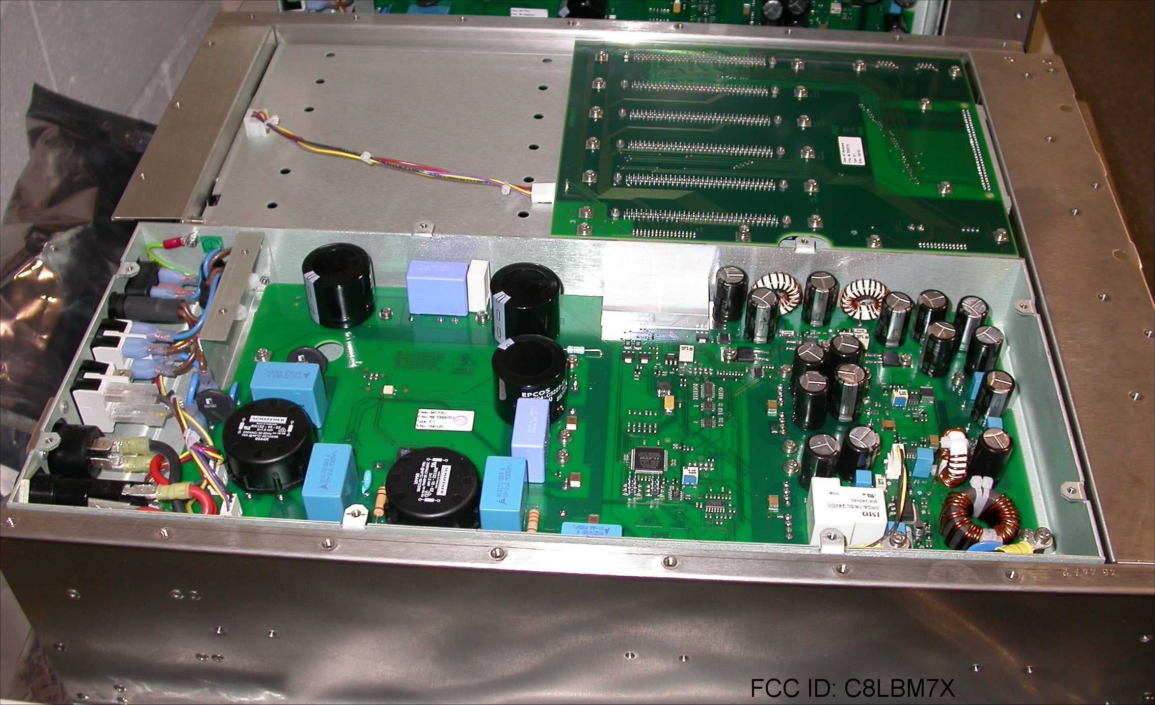
C8LBM7X
Feb 03, 200850W Transceiver
Equipment Class
TNB - Licensed Non-Broadcast Station Transmitter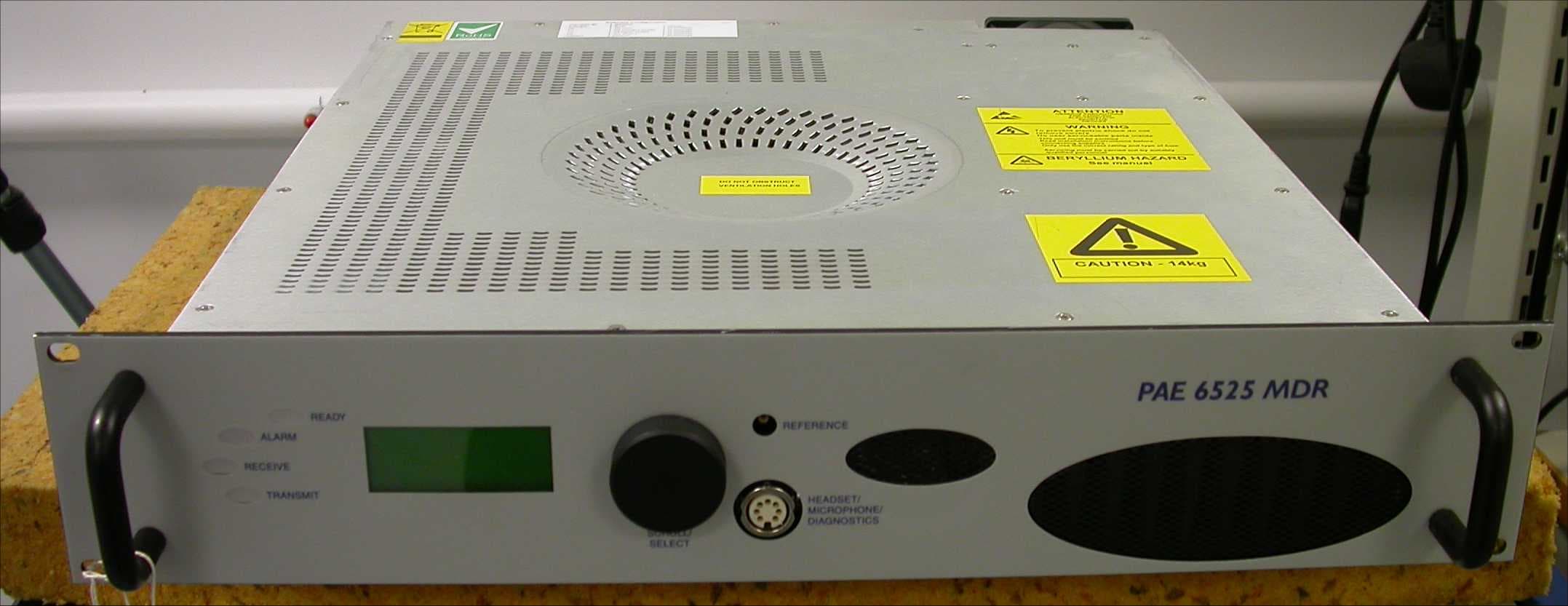
C8LB6525MDR
Aug 01, 2007Multimode VHF Ground to Air Transceiver
Equipment Class
TNB - Licensed Non-Broadcast Station Transmitter
C8LB63300HS
Jun 06, 2007VHF Ground to Air Transmitter
Equipment Class
TNB - Licensed Non-Broadcast Station Transmitter
C8LB6350-S2
Oct 02, 2005VHF ground to air transmitter
Equipment Class
TNB - Licensed Non-Broadcast Station Transmitter
C8LB6100-S2
Oct 02, 2005VHF fixed ground based aeronautical receiver
Equipment Class
CXX - Communications Rcvr for use w/ licensed Tx and CBs