C8LBT6MBS
Park Air Systems Limited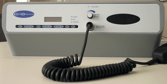
Click to zoom
Application Details
- Equipment Class
- TNB - Licensed Non-Broadcast Station Transmitter
- Date of Grant
- Dec 04, 2000
- Application Purpose
- Original Equipment
- Date of Application
- Oct 09, 2000
- Frequency Range
- 118.00000000 - 136.97500000
- Company
- Park Air Systems Limited
- Country
- United Kingdom
Documents & Files
Document Text
Text extracted from the exhibit documents filed with the FCC. Open a document above to read the original.
Users Manual
T6M Base Station User Guide Handbook Part Number: 31-360T6MBS Handbook Title:T6M Base Station User Guide Handbook Part Number:31-360T6MBS Issue Number:one Date of Issue:September 2000 Published by:Park Air Electronics Northfields Market Deeping Peterborough England Telephone:From UK, 01778 345434 From outside UK, 44 1778 345434 Fax:From UK, 01778 342877 From outside UK, 44 1778 342877 T6M Base Station User Guide Page 2 Amendment Record Amendments to this User Guide, initiated by PAE, are recorded in the following table. Amendment Number Incorporated by: DateBrief Details Modification Record Modifications to the T6M base station, authorized by PAE, are recorded in the following table. Modification Number Embodied by:DateBrief Details T6M Base Station User Guide Page 3 Changes or modifications to the T6M base station that are not expressly approved by Park Air Electronics could void your authority to operate the equipment. SAFETY Warnings [Failure to comply with warnings can result in personal injury, fire, or electric shock.] q DO NOToperate equipment at high volume levels. Hearing experts advise against continuous high volume operation. If you experience ringing in your ears, reduce the volume level, or discontinue use. q The Radio module's power amplifier circuit contains beryllium oxide that can be extremely toxic. No instructions within this user guide remove any of the radio module's covers so users are not exposed to a potential beryllium hazard. If the radio module is to be disposed of, users must be aware of current disposal regulations regarding equipment containing beryllium. q The antenna used with this radio equipment must be installed such that the resultant radiated field strength is below 10 W/m ²in areas normally accessible to personnel. q The base station can be fitted with an optional internal battery. It is a sealed lead-acid type with a thixotropic electrolyte. The battery has self sealing safety vents that may release small quantities of gas under extreme conditions. Because of this, users must ensure that the enclosure's vents are always free from obstruction. FEDERAL COMMUNICATIONS COMMISSION (FCC) REGULATIONS q This device complies with Part 15 of the FCC Rules. Operation is subject to the condition that this device does not cause harmful interference. q You are required to obtain a station licence before transmitting from your base station. q This equipment is only licenced for operation on 25 kHz channel spacing. Operation on 8.33 kHz channel spacing is not allowed within the USA. q The base station power output must not exceed the output necessary for satisfactory technical operation taking account of local conditions and the area to be covered. q The base station's frequency and parameters should be checked by authorized service personnel before use, and at least yearly thereafter. T6M Base Station User Guide Page 4 FOREWORD This user guide describes the purpose, installation, and operation of the Park Air Electronics (PAE) T6M base station. Read all instructions given in this user guide before operating the equipment. TRADEMARKS The following trademarks are used in this user guide. IBMIs a registered trademark of International Business Machines. MicrosoftIs a registered trademark of Microsoft Corporation in the USA and other countries. WindowsIs a registered trademark of Microsoft Corporation in the USA and other countries. T6M Base Station User Guide Page 5 T6M Base Station User Guide Page 6 CONTENTS SAFETY4 Federal Communications Commission (FCC) Regulations4 Foreword5 Trademarks5 Chapter 1 - Overview9 About this Handbook9 Associated Handbook9 Introduction to the T6M Base Station9 Facilities10 Remote Controllers10 Power Supplies10 Programming the Base Station's Personality10 Options11 Internal Battery11 Rack Mount Option11 Local Monitoring of Transmitted Audio11 Chapter 2 - Specification13 General13 Dimensions and Weight14 Input Supplies14 ac Supply14 dc Supply14 Optional Internal Battery14 Receive Circuit15 Transmit Circuit15 Chapter 3 - Operation17 Introduction17 Front Panel Controls18 Display18 Transmit Indicator18 Busy Indicator18 Power Indicator18 Microphone/Diagnostics Connector18 Volume Control18 External Tx Inhibit Indicator18 Battery Indicator18 Loudspeaker Grille18 PRI Button19 SQL Button19 SELsand SELtButtons19 T6M Base Station User Guide Page 7 CHsand CHtButtons19 SCN Button19 VOLsand VOLtButtons19 Power Button19 Switching On and Off20 Operating the Base Station in Normal Mode21 Selecting Normal Mode21 Selecting a Channel Frequency21 Transmitting and Receiving21 Switching and Adjusting the Squelch Facility21 Operating the Base Station in Priority Mode23 Selecting Priority Mode23 Selecting a Priority Channel Frequency23 Transmitting and Receiving23 Operating the Base Station in Scan Mode24 Selecting Scan Mode24 Selecting a Scan Group24 Transmitting and Receiving24 Programmable Options25 Display Blanking25 Warning Beeps25 Key Beeps25 Transmit Inhibit26 Maximum Transmit Time26 Front Panel Display for 25 kHz and 8.33 kHz Channel Spacing26 Fault and Error Codes28 Chapter 4 - Installation29 Introduction29 Unpacking30 Setting Internal Links30 Siting the Base Station31 Connecting a T6M Controller to the Base Station31 Connecting an antenna31 Connecting the Chassis Stud to Earth31 Connecting a microphone32 Securing the Microphone Bracket32 Connecting External Facilities33 Connecting a dc Input Supply35 Connecting an ac Input Supply36 Connecting a PC to the Base Station36 Chapter 5 - Programming the Base Station37 Introduction37 Programmable Options39 Display Blanking39 T6M Base Station User Guide Page 8 Warning Beeps39 Key Beeps39 Hold on Scan Mode40 Installing the Programming Software onto a Laptop, or PC40 Creating a New Personality40 Saving a Personality44 Opening a Saved Personality45 Loading a Personality into the Radio45 Reading a Personality from the Radio45 Printing a Personality Report46 Chapter 6 - Spares47 Introduction47 List of Spares47 Chapte…
Text truncated - open the document above for the full version.
Cover Letter(s)
Northfields, Market Deeping, Peterborough, PE6 8UE, England. Tel: +44 (0) 1778 345434 Fax: 342877 Sales Fax: 341286 www.parkair.co.uk Registered in England 1951792 An ISO9001 Approved Company A subsidiary of Northrop Grumman Corporation 9 October, 2000 Federal Communications Commission Equipment Approval Services P.O. Box 358315 Pittsburgh PA 15251-5315 USA Ref: FCC ID C8LBT6MBS Application EA 98998 FRN 0003-7782-63 Dear Sirs, Please find enclosed an application for Type Certification of a VHF aeronautical transceiver under Part 87 rules. This transceiver consists of an unmodified mobile radio (FCC ID C8LBT6M Application EA97773), an AC power supply and an interface module mounted in a moulded cabinet. This radio is capable of operating with channel spacing’s of 8.33kHz and 25kHz however, for the American market the equipment shall only be sold for operation on 25kHz-channel spacing. Only radios supplied for operation on 25kHz shall be marked with the FCC ID number. Since the RF parameters are governed by the mobile radio and this remains unmodified, please refer to the Mobile application for RF performance information regarding this application. The modulation input is routed via an interface module so I have enclosed a supplementary report covering the modulation characteristics. Only line bufering / level shifting is employed on this board so the modulation characteristic is essentially the same as the mobile on its own. Also included is a brief extract from the EMC approvals report produced by Cambridge Test & Measurement Services which shows compliance with EN55022 Class B for emissions. The UK Type examination certificate based on this report is also filed. Should you require further information in support of this application please do not hesitate to contact me. Yours faithfully, Allan Horsfield Principal Engineer Message: Commercial, in Confidence EMC and Approvals
Cover Letter(s)
9 October, 2000 FAA Spectrum Engineering Division 800 Independence Avenue SW Washington, DC 20591 FCC ID C8LBT6MBS FCC Application EA98998 Dear Sirs, Please be advised that we are making an application to the Federal Communications Commission to obtain an Equipment Authorisation Grant for Park Air Electronics VHF ground station transceiver model number BT6MBS. The equipment provides 8W RF output power in the 118 – 136.975 MHz band employing A3E (AM) modulation. The radio incorporates the PAE mobile radio BT6M (FCC ID C8LBT6M) together with an interface and AC power supply in a moulded cabinet to form a low power transceiver. A summary of the equipment’s performance is attached which is taken from the mobile radio test data. Yours faithfully, Allan Horsfield Principal Engineer EMC and Approvals FAA Notification of FCC Type Acceptance Application for PAE BT6MBS. General FCC NumberC8LBT6MBS ManufacturerPark Air Electronics Ltd. England. Type T6MBS VHF transceiver Model NumberBT6MBS RF Output Power8 Watts Antenna port50R N-type connector Frequency range118 MHz to 136.975 MHz. Method of tuningPre programmed frequencies selected by front panel controls. Channelling capability25 kHz and 8.33kHz. Emission bandwidthWithin FCC limits see attached report summary Emission type6K0A3EJN Emission/harmonicsSee attached report summary Description The Park Air Electronics (PAE) transceiver Type T6MBS is a multi-channel VHF AM equipment operating in the frequency range 118 to 137 MHz with a bandwidth of 8.33 or 25 kHz. The transceiver is designed for desktop mounting, but a rack version is also applicable. The equipment, which operates from a mains or DC supply incorporates automatic change-over in the event of mains failure The transceiver provides a nominal 8 watt output. This transceiver utilises a mobile radio model no. BT6M (C8LBT6M) as the basic RF source. An interface allows basic remote control (keying and audio) of the radio via 4 analogue ports. The required frequencies, priority frequencies and scan facilities are normally programmed, to the user’s requirements, during manufacture or by the equipment supplier. If a user wishes to programme the equipment, then disk based programming software and a programming lead can be supplied by PAE. The FCC application only covers operation on 25kHz channel spacing. PAE BT6MBS VHF transmitter emission performance summary: All results taken from report number CTMS 2000/1301a produced by Cambridge Test and Measurement Services * and submitted to the FCC supporting an original application for Grant of Equipment Authorisation for C8LBT6M mobile radio. This equipment incorporates the above mobile radio. No electrical or software changes are made to the radio. Occupied Bandwidth - 47 CFR 2.1049 (1) Occupied Bandwidth Rules Parts 2.1049 and 87.139 Mask showing compliance with 25 kHz channel spacing 0 - 10 - 20 - 30 - 40 - 50 - 60 - 70 - 80 - 90 -100 STOPP ED AT 25dBRB 300Hz# A: POS RLV: 9.1dBmST 5.0sVB 300Hz# CENTER:127.500 0MHz [BAND ~] SPAN:150kHz freq TR-A Results from mobile radio test report. Further tests to EN55022 Class B were performed on the base station model and showed compliance with the standard. A Type Examination Certificate No. 04/13 was granted by the UK Civil Aviation Authority in respect of EMC testing on the BT6MBS. Results in accordance with Part 2.1051 and 87.139 Emission Limits Note: Emissions 20dB below limit are not required to be listed Carrier Frequency (Fc) : 127.5 MHz Absolute LevelLevel (relative to RF Pow er 8W) dB w .r.t limit of 43+10 log pow er FrequencyIdentitydBmdBcRemarks (MHz)limit - 13limit - 52 127.398Spurio us- 35.7- 74.7All others > 127.603Spurio us- 39.2- 78.220 dB within 255.0002fc- 47.5- 86.5Specification 382.500 3fc- 53.7 - 92.7Limit. * FCC Registration Number 93395 Results in accordance w ith Part 2.1053 and 87.139 Emission Limits Notes: 1Emissions 20dB below limit are not required to be listed 2Following a pre-scan below 30MHz, no emissions detected greater than 20dB above specification limits Carrier Frequency (Fc) : 127.5 MHz FrequencyIdentity Absolute Level dBm Level (relative to RF Pow er 8W) dB w .r.t limit of 43+10 log pow er (MHz)limit - 13limit -52 dBcRemarks 176.94Spurio us- 63.2- 102.2All greater than 20dB 255.60Spurio us- 65.0- 104.0within Specification Limit. Internal view showing mobile radio
ID Label/Location Info
FCC ID Label Equipment identification label positioned on rear panel of equipment
Internal Photos
BT6MBS Inter nal PhotoFCC ID C8LBT6MBS FCC ID C8LBT6MBS T6MBS Internal View Note • Mobile radio Model BT6M FCC ID C8LBT6M is mounted on the left and butts up to the front panel. • The Battery pack in the centre is optional. Standard model incorporates a 33mFd capacitor in this position. • AC power supply is situated at the right hand side adjacent to the capacitor/battery. • No changes to software or hardware are made to the radio FCC ID C8LBT6M.
Internal Photos
FCC ID C8LBT6MBSInternal PhotosEA98998 Fro nt pa ne l mic ro pho ne input a nd vol ume co ntro l FCC ID C8LBT6MBSInternal PhotosEA98998 Inte rface Module FCC ID C8LBT6MBSInternal PhotosEA98998 Power Supply Module
RF Exposure Info
FCC ID C8LBT6MBSRF RadiationEA98998 Park Air Electronics Limited BT6MBS Statement on RF Safety Requirements. Reference FCC Rules Part 1 para. 1.1307, 2.1093. The PAE base station model BT6MBS is a low power transceiver operating in the 118 –137 MHz band with an RF output power of 8W nominal. This equates to a maximum field strength not exceeding 22V/m. (based on a half wave dipole with a gain of 1.64 times that of an isotropic radiator). This radiated level equates to a Power density of 1.3Wm -2 which is a minimum risk level. This equipment is designed for operation with a fixed site antenna. To ensure correct operation, the user guide issued with the equipment, carries the following warning on antenna use: The antenna used with this radio equipme nt must be installed such that the resultant radiated fie ld stre ngt h is be low 10 W/ m² i n a re as no rma lly acce ssible to pe rsonne l. This level is lower than the recommendations given by the NCRP and EN60215:1996. The equipment meets the requirements of EN60215 Clause 22 regarding Harmful Radiation (<100W/ m -2 ). The antenna connector is fitted with a warning symbol in accordance with EN60215 Clause 22 : Northfields, Market Deeping, Peterborough, PE6 8UE, England. Tel: +44 (0) 1778 345434 Fax: 342877 Sales Fax: 341286 www.parkair.co.uk Registered in England 1951792 An ISO9001 Approved Company A subsidiary of Northrop Grumman Corporation
Schematics
MOBILE_ON TP1 C31n 0V T6M MIC Drive C106 1n C105 1n C27100u C24 100n 0V 0V 0V C107 1n C108 1n C109 1n 3 CN9:C C39 47u 3V3D1 R4100k TR1 BC847 0V Pulls to GNDwhen T6M is on 0V Audio to T6MMIC Connector R31k5 1k R20 TO TP29SHEET 3 C1171n NF 0V 14 CN7:N BS LS - 17 CN7:Q BS LS - R241R0 C19100n 16 CN7:P TP9 BS LS + C23 470u C22 470u 7 CN7:G 0V VOL Out 13 CN7:M BS LS + 8 CN7:H VOL Return 0V 1nC115 0V 1nC116 LOUDSPEAKER DRIVE R1298k2 +5V V_UNREG_SW 47R R32 C28 1n8 C29 470u 1 + 2 - 4 IC3 TDA2003 R27220R R282R2 C741u 470RR128 0V 2u2 C33 100k R64 2k7 R18 9 - 10 + 8 IC2:C TL084 C59 2u2 +5V IC3Decoupling HSMS2822 D3 C57 1n RX AUDIO DETECT CIRCUIT 20k R6 HSMS2822 D9 +5V 2k2 R86 1k2 R63 TR2FZT653 13 - 12 + 14 IC2:D TL084 +5V 10k R72 12k R74 R75 2k2 2u2 C62 1k8 R70 9 CN5:I 8 CN5:H 7 CN5:G 9 CN4:I 0V 7 CN4:G 8 CN4:H C102 1n C103 1n C104 1n 0V IC3 V_UNREG_SW 53 6 CN5:F 5 CN5:E 5 CN4:E 6 CN4:F C100 1n C101 1n C90 1n 5 CN3:E 6 CN3:F 0V 0V C91 1n C95 1n C96 1n 3k3 R71 0V 7 CN3:G 8 CN3:H 9 CN3:I 0V C92 1n C93 1n C94 1n C97 1n C98 1n C99 1n 0V 1nC114 1nC65 TP8 Sidetone 3 CN7:C 6 CN7:F MIC GND 2 CN8:B 4 CN8:D 8 CN8:H Not usedNot usedNot usedMIC in 1 CN7:A 0V 1n NFC111 0V C128 2u2 IC1 11 0V 4 V_UNREG_SW TP6 MIC Audiofrom front panel 1n NFC113 +5V 200R R25 C21 47u 13 - 12 + 14 IC1:D TL084 22k R33 3k3 R34 2k2 R31 HEADSETDRIVE C25 1n8 8k2 R29 2 - 3 + 1 IC1:A TL084 0V C12 100n 2k2 R12 C10 10n IGNSNS V_UNREG_SW 7 CN8:G 3 CN8:C 1 CN8:A RECEIVED AUDIO - DIFFERENTIAL TO SINGLE ENDED CONVERSION Speaker +Speaker - Ignition Sense C1101n NF 1k R7 1k R8 IC1Decoupling V_UNREG_SW C110u 4 11 2 - 3 + 1 IC2:A TL084 +5V V_UNREG_SW 0V IC2 C26 100n 10k R22 C32 2u2 TP10 Volume Controlled Audiofor loudspeaker/headset +5V 5k6 R19 5k6 R21 IC2Decoupling 0V 100n C18 MIC AUDIOAMPLIFY AND FILTER D4 BAS16 BAS16 D5 33k R26 C1410u 6 - 5 + 7 IC2:B TL084 +5V 22nC30 C35 1n8 3k3 R30 3k3 R35 3k3 R36 R16k8 C6 68n 0V 0V Select type of audio forBS speaker and headset 5R6 R42 0V C43 2u2 VCCS Audiofor Transmission C41 10n C40 47u 100kR73 1k2 R45 1k2 R78 RL2:B TP14 TP17 TP19 DRIVE FORT6M MIC INPUT Audio forTransmission 0V 0V 5R6 R46 Received Audio or Audio forTransmission (but not MIC audio) T1 0V R761k2 100kR92 RL1:B TP15 Received Audio MIC Audio C38 47u 0V 2 CN2:B 3 CN2:C 1 CN2:A 4 CN2:D 0V0V RCU1 GNDRCU1 PTTRCU1 LINE-RCU1 LINE+ C86 1n D151000V1000VD21 0V 1 CN4:A 3 CN5:C 2 CN5:B 4 CN4:D 2 CN4:B 3 CN4:C 1 CN5:A 4 CN5:D RCU3 GNDRCU3 LINE-RCU3 PTTRCU4 LINE-RCU4 LINE+RCU4 PTTRCU4 GND C52 1n C51 1n 0V C87 1n C88 1n C89 1n 0V 4 CN3:D 3 CN3:C 2 CN3:B 1 CN3:A RCU2 PTTRCU2 LINE-RCU2 LINE+RCU2 GNDRCU3 LINE+ 0V C81 1n C82 1n C83 1n C85 1n 0V C84 1n 9 CN2:I 8 CN2:H 7 CN2:G 0V 13 CN6:M 12 CN6:L 15 CN6:O C77 1n C78 1n 6 CN2:F 5 CN2:E 1 CN6:A 11 CN6:K C66 1n 10k R40 +5V R47 3k3 0V 9 - 10 + 8 IC1:C TL084 TAPE OUTPUT DRIVE C45 47u TP18 5R6 R88 31st July 2000T6M Base Station Interface 10k R41 0V 4 CN6:D C1251n Rx Squelch C80 10u 6 - 5 + 7 IC1:B TL084 Rx’d andTx’d audio JP1 Rx’d audio only +5V 330R R48 R891k2 C44 2u2 1k2 R50 5R6 R56 0V0V 10k R54 C42 1n8 Tape Audio 0V 0V 0V C461n 6 CN6:F 5 CN6:E 0V 0V0V T3 C471nC501n VCCS RX-VCCS RX+ D171000VD361000VD371000V 0V 0V 7 CN6:G VCCS_PHANT_PTT RCU_PHANT_PTT RCU_LINE_PTT 0V 8 CN6:H T2 C491n To D14-3Sheet 2To D12-3Sheet 2To D11-3Sheet 2 VCCS TX- VCCS TX+ C53 1n 0V D161000V 3 CN6:C 2 CN6:B 0V0V0V 0V0V T4 C481nC541n Tape-Tape+ D181000VD381000V D GA10510 S Beaton / D Hand 14 0V 9 CN6:I 10 CN6:J VCCS PTT- VCCS PTT+ 1nC55 14 CN6:N C561n 0V Ext Tx Inhib D13 BAS16 R9047k NF 0V R13247k NF R13147k NF R12747k NF R9347k NF V_UNREG_SW TR3BC847 R1110k D29 BAS16 BAS16 D33 0V V_UNREG_SW IC4 R15 47k 0V 0V R61 10k V_UNREG_SW 1k R52 100n C129 TR10 BC857 PTT INHIBIT 10k R60 C133100n 18 V_UNREG_SW C31100n 0V 435 276 RESET O/P TRIG IC4 CA555 2u2 C17 0V D2 5.1V 0V 150k R17 IC4Decoupling 680R R9 D10 BAS16 D11 BAS16 D14 BAS16 D12 BAS16 RCU_PHANT_PTT From T1-2Sheet 1 VCCS_PHANT_PTT From T2-2Sheet 1 RCU_LINE_PTT 2 CN7:B MIC PTT 0V C124 1n 5 CN7:E 0V 1nC118 0V 1nC119 100k R23 0V VFP TxD From pin 4on CN2,3,4,5Sheet 1 4 CN7:D VFP RxD IC5 15 +5V C36 100n +5V 0V 14 0V BAS16 D20 TR8BC857 +- RL1:A RL1 switchon sheet 1 10k R53 AUDIO SWITCHING (RELAYS 1 AND 2)AND PTT OF T6M BY ALL SOURCES OF PTTINCLUDES PTT INHIBIT C13 100n 1kR43 0V on PTT fromany source TP16 1k R38 C34 100n V_UNREG_SW 10k R37 D8 BAS16 RL2 switchon sheet 1 TP13 NF TP12 NF D7 BAS16 +- RL2:A TR6 BC857 V_UNREG_SW 100n C131 2 C1+ 4 C1- 9 R1OUT 11 T1IN 12 FORCEON 16 FORCEOFF 1 EN 10 INVALID 13 T1OUT 8 R1IN 6 C2- 5 C2+ 7 V- 3 V+ IC5 MAX3221E 0V +5V TP7 +5V when VFPlead attached 3 21 EN IC6:A 74HC126 6 54 EN IC6:B 74HC126 1k R59 100n C16 C8 100n 100nC11 0V C15 100n 0V PROGRAMMING LEADRS232-TTL Conversionand VFP lead detect TP2 T6M MIC CONNECTOR 2 CN9:B PTT/RxD IC6 7 0V 14 5V_PERM V_UNREG 5V_PERM 560RR130 1 CN9:A TxD 1n C2 4 CN9:D On hook MIC Gnd 5 CN9:E 6 CN9:F Call End 0V 1n C5 1n C4 8 9 10 EN IC6:C 74HC126 270R R5 T6M Base Station Interface 31st July 2000 D6 BAS16 C132 100n 10k R58 R391k D19 BAS16 R493k3 C130 100n R621k 0V TR7BC847 TP11 PTT to T6M R57 10k TR9BC847 TR11 BC857 T6M PTT 0V IC6Decoupling 5.1V D34 0V 0V 100n C37 11 1213 EN IC6:D 74HC126 C123 1n 0V 11 CN7:K INHIB LED D 24 GA10510 S Beaton / D Hand R9827k C6910u V_UNREG 220k R97 C6810u TR21BC847 0V R9910k FROM TR1SHEET 1 MOBILE_ON TP29 0V 100RR100 Low whenT6M is on Switch closed= 11.5 TO 15.5V 1 CN1:A 2 CN1:B SUPPLYON\OFFSWITCH BAS16D25 15 CX 14 RCX 12 1113 R 9 10 IC11:B HEF4528 0V R95 10k R94 10k R103 10k 0V 9 SECOND POWER DOWN CIRCUIT TP20 C6010u R661k 470k R67 BAS16 D22 2k2 R87 3 + 2 - 1 IC9:A LM2903M Output low for> 9 secondsafter switch off TP22 R4422k V_UNREG 47kR68 V_UNREG IGNITION SENSE3 SECOND PULSECIRCUIT R5510kR8318k V_UNREG 5 + 6 - 7 IC9:B LM2903M V_UNREG R8410k C7210u R961M0 1 CX 2 RCX 4 53 R 7 6 IC11:A HEF4528 IC11 V_UNREG 16 0V 8 V_UNREG C67100n 0V TP23 0V TP28 0V MBR2535CTL D28 D23 MBR2535CTL Common Supply Pointfrom all supplies C582u2 C20100n TP21 R80 2k2 NF R79 2k2 NF 1 CN10:A 2 CN10:B 3 CN10:C 4 CN10:D BATTERY 2 CN12:B 1 CN12…
Text truncated - open the document above for the full version.
Test Report
EQUIPMENT : BT6MBSSupplement to Test Report: SUP-BT6MBS-001 FCC ID C8LBT6MBSDate: 9-Oct-00 Page1 FCC ID C8LBT6MBS Modulation Characteristics – 47 CFR 2.1047 (a) The transceiver is operated under standard test conditions and the output monitored with a modulation analyser via an attenuator of nominal impedance matching that of the transmitter. A test signal of 1000Hz sine wave is applied to the facilities connector modulation input pins, and the level adjusted to give 30% depth of modulation. Ensuring the audio input level is maintained constant, the modulation frequency is varied from 100Hz to 10kHz. The variation in depth of modulation is observed and recorded. The modulation characteristic was measured in accordance with the following test configuration, using the test instruments listed. Test instruments used: RF Attenuator:Bird 30dB, 500W Type 8325 Serial No. 102 AF Oscillator:H P Audio Analyser Type HP8903B Cal due 6-21-2001 AC Voltmeter:Philips PM2519 Serial No.DY0101684 Cal due 6-0 5-2001 Modulation Analyser:H P Audio Analyser Type HP8901BCal due 6-21-2001 EUT AF Oscillator AC Voltmeter 30dB AttenuatorModulation Analyser EQUIPMENT : BT6MBSSupplement to Test Report: SUP-BT6MBS-001 FCC ID C8LBT6MBSDate: 9-Oct-00 Page2 FCC ID C8LBT6MBS Results in accordance with Part 2.1047(a) and 87.141 Modulation Requirements. Modulation characteristic Level (dB) -40 -35 -30 -25 -20 -15 -10 -5 0 5 100100010000 Modulation Frequency dB EQUIPMENT : BT6MBSSupplement to Test Report: SUP-BT6MBS-001 FCC ID C8LBT6MBSDate: 9-Oct-00 Page3 FCC ID C8LBT6MBS Modulation Characteristics – 47 CFR 2.1047 (b) The transceiver is operated under standard test conditions and the output monitored with a modulation analyser via an attenuator of nominal impedance matching that of the transmitter. A test signal of 1000Hz sine wave is applied to the facilities connector modulation input pins, and the input level varied between –50dBm and +10dBm and the variation in the depth of modulation is observed and recorded. The test was repeated with the test modulation frequency of 300Hz and 3000Hz The modulation limiting characteristic was measured in accordance with the following test configuration, using the test instruments listed. Test instruments used: RF Attenuator:Bird 30dB, 500W Type 8325 Serial No. 102 AF Oscillator:H P Audio Analyser Type HP8903B Cal due 6-21-2001 AC Voltmeter:Philips PM2519 Serial No.DY0101684 Cal due 6-0 5-2001 Modulation Analyser:H P Audio Analyser Type HP8901BCal due 6-21-2001 EUT AF Oscillator AC Voltmeter 30dB AttenuatorModulation Analyser EQUIPMENT : BT6MBSSupplement to Test Report: SUP-BT6MBS-001 FCC ID C8LBT6MBSDate: 9-Oct-00 Page4 FCC ID C8LBT6MBS Results in accordance with Part 2.1047(b) and 87.141 Modulation Requirements. Modulation Limiting Characteristic Modulation Depth vs Audio Line Input Level 0 10 20 30 40 50 60 70 80 90 100 -50-40-30-20-1001020 dBm % Modulation 1kHz 300Hz 3kHz
Test Report
EQUIPMENT:BT6MBS Transceiver TEST REPORT NUMBER: CTMS 00/1519a Page 1 of 70 EMC TEST REPORT PARK AIR ELECTRONICS LTD. BT6MBS TRANSCEIVER To: PAE Test Plan 001 SEPTEMBER 2000 PROJECT FILE NUMBER: 00/1519a PREPARED FOR: Park Air Electronics Ltd. Northfields Market Deeping Peterborough PE6 8UE EQUIPMENT:BT6MBS Transceiver TEST REPORT NUMBER: CTMS 00/1519a Page 9 of 70 2. Test House Details All of the tests described in the following report were performed at Cambridge Test and Measurement Services Limited (CTMS). The address is as follows: Cambridge Test and Measurement Services Limited PO Box 465 St. Andrews Road Cambridge CB4 1ZJ England Tel: (+44) (0)1223 876876 Fax: (+44) (0)1223 876851 2.1 UKAS Accreditation Cambridge Test and Measurement Services is a UKAS Accredited test house, UKAS Testing No. 1831 and is Accredited to undertake Category 0, UKAS testing. All tests in this report are compliant with the UKAS Accreditation Standard. 3. Customer Details This report was prepared for: Mr Allan Horsfield Park Air Electronics Ltd. Northfields Market Deeping Peterborough PE6 8UE EQUIPMENT:BT6MBS Transceiver TEST REPORT NUMBER: CTMS 00/1519a Page 18 of 70 8. Summary Of Test Results The following table shows a summary of all the test results. For more detail refer to the respective section. 8.1 Test Result Summary Table PortEMC PhenomenaBasic StandardCompliance Status Emissions EnclosureRadiated EmissionEN 55022 Class BComplied (Mode 1 & 2) AC MainsConducted EmissionsEN 55022 Class BComplied (Mode 1 & 2) DC MainsConducted EmissionsEN 55022 Class BComplied (Mode 1 & 2) AC MainsHarmonicsEN 61000-3-2Complied (Mode 1) AC MainsFlickerEN 61000-3-3Complied (Mode 1) Immunity EnclosureRadio-Frequency Electromagnetic Field. Amplitude Modulated. EN 61000-4-3Complied (Mode 1 & 2) .Electrostatic DischargeEN 61000-4-2Complied (Mode 1 & 2) Ports for Process, Measurement & Control Lines Radio-Frequency Common Mode. EN 61000-4-6Complied (Mode 1 & 2) Fast TransientsEN 61000-4-4Complied (Mode 1 & 2) Input and Output AC Power Ports Radio-Frequency Common Mode EN 61000-4-6Complied (Mode 1 & 2) Fast TransientsEN 61000-4-4Complied (Mode 1 & 2) Surges, Line to Earth, Line to Line EN 61000-4-5Complied (Mode 1 & 2) Voltage DipsEN 61000-4-11Complied (Mode 1) Voltage InterruptionsEN 61000-4-11Complied (Mode 1) Voltage VariationEN 61000-4-11Complied (Mode 1) Input and Output DC Power Ports Radio-Frequency Common Mode EN 61000-4-6Complied (Mode 1 & 2) Fast TransientsEN 61000-4-4Complied (Mode 1 & 2) Surges, Line to Earth, Line to Line EN 61000-4-5Complied (Mode 1 & 2) Voltage DipsEN 61000-4-11Complied (Mode 1) Voltage InterruptionsEN 61000-4-11Complied (Mode 1) Voltage VariationEN 61000-4-11Complied (Mode 1) Mode 1: Transmitting full power. M = 0.80 at 1kHz. Modulation Mode 5K00A3EJN Mode 2: Equipment is in receive mode with an on channel signal level producing 20dB SINAD level. EQUIPMENT:BT6MBS Transceiver TEST REPORT NUMBER: CTMS 00/1519a Page 19 of 70 9. Measurements, Examination And Test Results 9.1 Radiated Emissions Transmit Mode PortEnclosure SpecificationEN 55022:1994 LimitClass B Measurement distance10m Temperature22 ̄C Humidity51% Frequency (MHz) PolarisationLevel (dBμV/m) Limit (dBμV/m) Margin (dBμV/m) Result 31.1340Horizontal27.530.02.5Complied 30.0600Vertical26.530.03.5Complied The plots for these tests can be seen in Appendix 1. 9.1.1 Test Equipment Used For Radiated Emissions DescriptionModel NumberCTMS Number Bilog antenna Chase CBL6141ATMS 933 Receiver Rhode & Schwarz ESVS10TMS 917 Partially lined screened roomRay Proof SR2TMS 817 PC Controller486, fitted with a GPIB interfaceNot Applicable PrinterHewlett Packard DeskJet 850CNot Applicable Coaxial cable4mTMS 123 Coaxial cable10mTMS 116 Coaxial cable40mTMS 122 MastChase CAM 6340Not Applicable TurntableCTMS, WT001Not Applicable PC Controller486, fitted with a GPIB InterfaceNot Applicable ThermometerRadio Spares TH200TMS 907 Tape Measure, Height GaugesNot ApplicableNot Applicable 9.1.2 Measurement Uncertainties Measurement Uncertainty For Radiated Emissions (95% confidence) +4.17dB / -4.21dB EQUIPMENT:BT6MBS Transceiver TEST REPORT NUMBER: CTMS 00/1519a Page 20 of 70 9.2 Radiated Emissions Receive Mode PortEnclosure SpecificationEN 55022:1994 LimitClass B Measurement distance10m Temperature22 ̄C Humidity51% Frequency (MHz) PolarisationLevel (dBμV/m) Limit (dBμV/m) Margin (dBμV/m) Result 31.0145Horizontal26.230.03.8Complied 31.1194Vertical26.130.03.9Complied 31.2020Vertical26.330.03.7Complied The plots for these tests can be seen in Appendix 1. 9.2.1 Test Equipment Used For Radiated Emissions DescriptionModel NumberCTMS Number Bilog antenna Chase CBL6141ATMS 933 Receiver Rhode & Schwarz ESVS10TMS 917 Partially lined screened roomRay Proof SR2TMS 817 PC Controller486, fitted with a GPIB interfaceNot Applicable PrinterHewlett Packard DeskJet 850CNot Applicable Coaxial cable4mTMS 123 Coaxial cable10mTMS 116 Coaxial cable40mTMS 122 MastChase CAM 6340Not Applicable TurntableCTMS, WT001Not Applicable PC Controller486, fitted with a GPIB InterfaceNot Applicable ThermometerRadio Spares TH200TMS 907 Tape Measure, Height GaugesNot ApplicableNot Applicable 9.2.2 Measurement Uncertainties Measurement Uncertainty For Radiated Emissions (95% confidence) +4.17dB / -4.21dB EQUIPMENT:BT6MBS Transceiver TEST REPORT NUMBER: CTMS 00/1519a Page 21 of 70 9.3 Conducted Emissions Transmit Mode PortAC Mains SpecificationEN 55022:1994 LimitClass B Measurement portsLive and Neutral Temperature22 ̄C Humidity45% FrequencyLine Level (dBμV)Limit (dBμV) MarginResult (MHz)QPAVEQPAVEQPAVE 0.174Live58.29-64.77-6.48-Complied 0.588Live42.5638.4556.0046.0013.447.55Complied 0.588Neutral40.0637.6756.0046.0015.948.33Complied The plots for these tests can be seen in Appendix 1. 9.3.1 Test Equipment Used DescriptionModel NumberCTMS Number LISNChase MN2053TMS 912 Transient limiterChase CFL9206TMS 905 ReceiverRhode & Schwarz ESHS10TMS 916 Coaxial cable4mTMS 123 Coaxial cable10mTMS 116 Partially lined scre…
Text truncated - open the document above for the full version.
Contact Information
Applicant
Philip Ackerman(Consultant Engineer)
Technical Specifications
| # | Rule Parts | Frequency Range | Power Output | Emission | Tolerance |
|---|---|---|---|---|---|
| 1 | 87 | 118 MHz - 136.975 MHz | 8 W | 6K00A3E | 1.0000000000 ppm |
Other Applications from Park Air Systems Limited
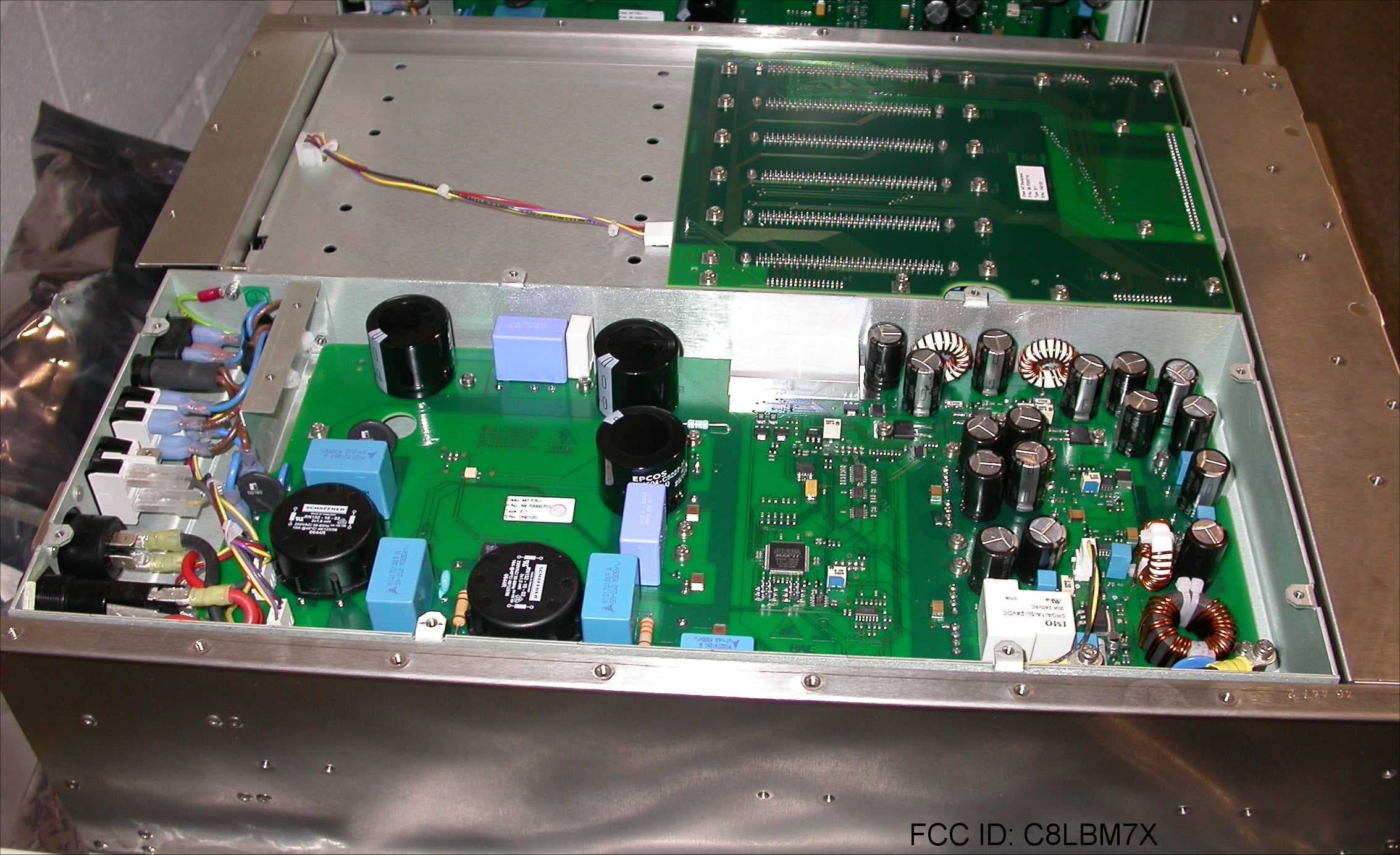
C8LBM7X
Feb 03, 200850W Transceiver
Equipment Class
TNB - Licensed Non-Broadcast Station Transmitter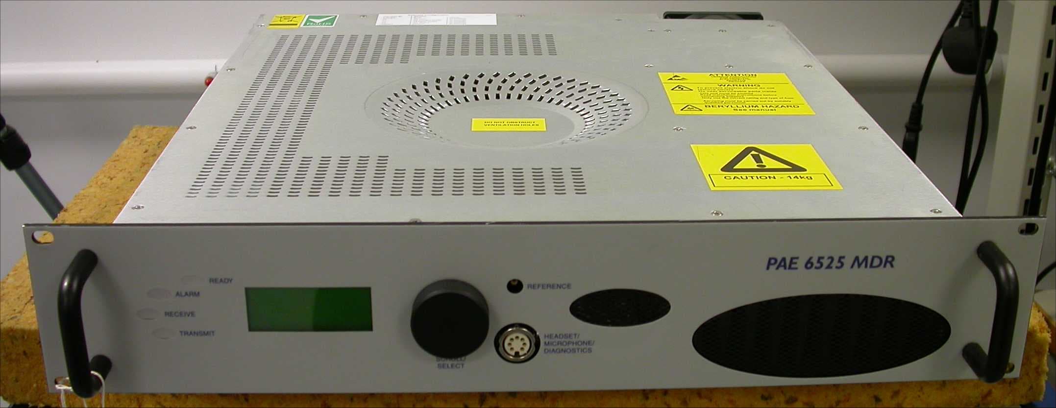
C8LB6525MDR
Aug 01, 2007Multimode VHF Ground to Air Transceiver
Equipment Class
TNB - Licensed Non-Broadcast Station Transmitter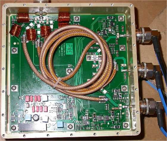
C8LB63300HS
Jun 06, 2007VHF Ground to Air Transmitter
Equipment Class
TNB - Licensed Non-Broadcast Station Transmitter
C8LB6350-S2
Oct 02, 2005VHF ground to air transmitter
Equipment Class
TNB - Licensed Non-Broadcast Station Transmitter
C8LB6100-S2
Oct 02, 2005VHF fixed ground based aeronautical receiver
Equipment Class
CXX - Communications Rcvr for use w/ licensed Tx and CBs