CA6330Digital Microwave Field Disturbance Sensor
Southwest Microwave Inc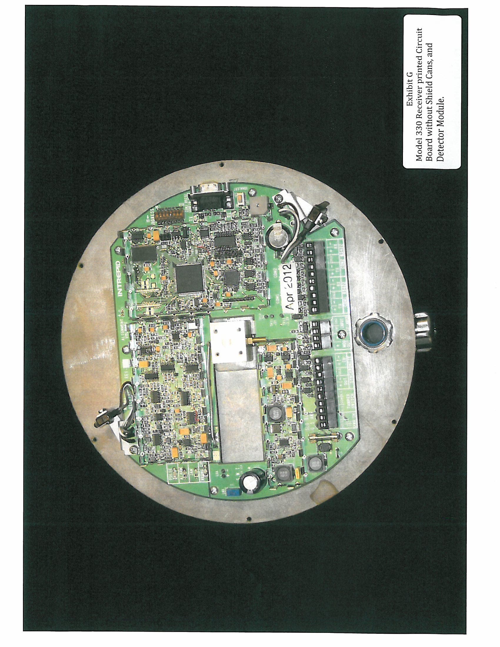
Click to zoom
Application Details
- Equipment Class
- FDS - Part 15 Field Disturbance Sensor
- Date of Grant
- Sep 12, 2012
- Application Purpose
- Original Equipment
- Date of Application
- May 23, 2012
- Equipment Note
- Digital Microwave Field Disturbance Sensor
- Frequency Range
- 24125.00000000 - 24125.00000000
- Company
- Southwest Microwave Inc
- Country
- United States
Documents & Files
Document Text
Text extracted from the exhibit documents filed with the FCC. Open a document above to read the original.
Users Manual
Version 0 Southwest Microwave, Inc. Security Systems Division INTREPID™ MicroWave 330 A DIGITAL MICOWAVE OUTDOOR PERIMETER INTRUSION DETECTION SYSTEM MicroWave 330 Installation and Operation Manual 2 Version 0 Trademark Notice and Certifications INTREPID™, MicroPoint™ and MicroTrack™ are registered trademarks of Southwest Microwave, Inc. Copyright 1995 and 2012 Southwest Microwave, Inc. All rights Reserved. FCC Notice MicroWave 330 is classified as a field disturbance sensor. This device complies with FCC Rules Part 15.245. Operation is subject to the following two conditions: This device may not cause harmful interference and this device must accept interference received, including interference that may cause undesired operation. Notice: changes or modifications not expressly approved by Southwest Microwave, Inc. could void the user’s authority to operate the equipment. This equipment has been tested and found to comply with the limits for a Class A digital device, pursuant to part 15 of the FCC Rules. These limits are designed to provide reasonable protection against harmful interference when the equipment is operated in a commercial environment. This equipment generates, uses, and can radiate radio frequency energy and, if not installed and used in accordance with the instruction manual, may cause harmful interference to radio communications. Operation of this equipment in a residential area is likely to cause harmful interference in which case the user will be required to correct the interference at his own expense. RoHS Compliant Radiation Safety The allowable standard minimum of safe radiation exposure level in the United States as established by the American National Standards Institute is 10mW/cm 2 . There is currently a proposal to drop this limit to 1mW/cm 2 . The average Southwest Microwave sensor surface radiation level (when in operation) is approximately.0186mW/cm 2 or 1/50 of the proposed lower standard. This level rapidly dissipates at distances from the unit. For example, at one meter, the figure reduces to .0012mW/cm 2 or 1/800 of the proposed level. Copyright Southwest Microwave, Inc. May 2012 Southwest Microwave, Inc. 9055 South McKemy Street Tempe, Arizona 85284-2946 Tel: (480) 783-0201 Fax: (480) 783-0401 Email: [email protected] Web: www.southwestmicrowave.com 3 Version 0 INTREPID™ MicroWave 330 Software Southwest Microwave, Inc. thanks you for your purchase of the INTREPID MicroWave 330 Digital Microwave Intrusion Link. Please refer to the Universal Installation Service Tool II (UIST II) for the software setup of this sensor. One disk is required to setup the system. It is called: Universal Installation Service Tool II (UIST II) This software is used to configure and set-up the system as well as being used for maintenance and troubleshooting the system. Software provided by Southwest Microwave, Inc. is subject to the license agreement terms of the individual product. A copy of the license agreement is available by contacting Southwest Microwave, Inc. 4 Version 0 Table of Contents 1. Introduction ................................................................................................................................................ 5 2. Hardware .................................................................................................................................................... 5 2.1 MicroWave 330 Link ............................................................................................................................ 5 2.2 Optional Power Supplies ...................................................................................................................... 6 2.3 Oprional Accessories ............................................................................................................................ 6 3. Principles of Operation and Detection ..................................................................................................... 6 3.1 Description ............................................................................................................................................ 6 3.2 Range of Operation ............................................................................................................................... 7 3.3 Overlaps ................................................................................................................................................ 8 3.3.1 High Security Overlaps ................................................................................................................... 9 3.4 Transmitter Block Diagram .................................................................................................................. 9 3.5 Receiver Block Diagram ..................................................................................................................... 10 3.6 Specifications ...................................................................................................................................... 11 4. Installation Instructions .......................................................................................................................... 13 4.1 Location of MicroWave 330 ............................................................................................................... 13 4.1.1 Required Area ................................................................................................................................ 13 4.1.2 Terrain ........................................................................................................................................... 14 4.1.2.1 Terrain in High Security Applications .................................................................................... 14 4.1.3 Physical Protection ........................................................................................................................ 15 4.1.4 Best Security ......................…
Text truncated - open the document above for the full version.
Operational Description
Digital Microwave link intrePiD™ Microwave 330 is a digital microwave field disturbance sen- sor providing protection for open areas, gates, entr yways, wall and rooftop applications. Based on Southwest Microwave’s field-proven microwave detection technology, it provides volumetric detection of human intruders with minimal environmental nuisance alarms. advanced digital signal pro- cessing (DSP) allows continuous monitoring of intrusion alarm and tamper switch status, received signal strength and detection parameters. Micro w ave 330 operates at k-band frequencies, achieving superior per- formance to X-band sensors. Because k-band is 2.5 times higher than X- band, the multipath signal generated by an intruder is more focused, and detection of slow-moving intruders is correspondingly better. at k-band frequency, the unit also has low susceptibility to outside inter ference from air/seaport radar or other microwave systems. a ntenna beam width is approximately 3.5 degrees in the horizontal and vertical planes for long range operation and superior beam control within narrow corridors. a dvanced receiver design increases detection prob- ability by alarming on partial or complete beam interruption, increase / decrease in signal level or jamming by other transmitters. automatic gain control (agc) compensates for var ying site or weather conditions. Six field-selectable modulation channels with narrow band filtering al- low multiple Micro w ave 330’s to operate simultaneously without mutual inter ference, and permit synchronous use with Southwest Microwave’s microwave transceivers. Units can also be stacked for the ultimate in detection per formance. as part of the new-generation intrePiD™ family, Microwave 330 net- works seamlessly with MicroPoint™ ii fence detection sensor and Micro t rack™ ii buried cable detection sensor using a common, open architecture communications protocol. Single PlatforM networking caPaBilitieS 244 M (800 ft) range k-BanD MUltiPath Detection 6 fielD-SelectaBle, crYStal-controlleD MoDUlation channelS BUilt-in SYnchroniZation PreventS interference Between SenSorS rf Power Monitoring for Path changeS Digital Signal ProceSSing for high PD / low nar keY featUreS PrinciPleS of oPeration anD Detection a typical system includes Microwave 330 sensors networked via rS422 serial data inter face using a universal intrePiD™ System controller. auxiliar y inputs or relay outputs may also be integrated using an intrePiD™ i/o Module. a point to point communications network distributes data among network devices. a microprocessor and proprietar y algorithms provide power ful Digital Signal Processing to recognize the unique bi-static digital signatures of intruders walking, jumping or crawling through the detection field. targets are classified and scored in real time at each sensor. 1000 events and alarms are stored in the receiver’s flash memor y. intrusion detection, using a modulated amplitude sensitive system (not Doppler), takes place within the invisible pattern of microwave energy existing between transmitter and receiver. changes in signal amplitude at the receiver are directly related to the object’s size and density, allowing the sensor to discriminate between objects. Micro wave 330 will alarm on average sized humans walking, running or crawling on hands and knees through the pattern. field adjustments can provide alarm on larger or smaller targets, depending on the specific application. the sur face mounted electronics and parabolic antenna of Microwave 330 are mounted on a rugged metal base-plate and covered by a molded aBS radome for all weather operation. Swivel mount permits precise setup and provides firm lock against movement. f or detailed information on application, installation and adjustment, consult Microw ave 330 t echnical Manual. tYPical Microwave 330 configUration DiagraM GCM II RS422 Star Configuration RCM II CM II PSM SDK Rx Rx Rx Rx Tx Tx Tx Tx RS422 Loop Configuration DC POWER DC POWER DC POWER DC POWER DC POWER DC POWER DC POWER DC POWER Other System Controller Options ™ Digital Microwave link inStallation anD Set-UP PerforMance featUreS anD BenefitS Microwave 330 transmitter and receiver are mounted on 1.2 m (4 ft) posts. connect each transmitter and receiver to a batter y- backed 10.5 to 60 vDc power supply. t amper ter minals on each transmitter may be connected to any receiver. connect a four-wire communication cable from the system controller to each receiver. no additional batteries, multiplex boards or exterior enclosures are required. Universal installation Ser vice tool ii (UiSt ii) software graphically controls and monitors sensor status, control parameters, signal strength, and intrusion / tamper alarm histor y with laptop convenience at each module via rS232 connection. Sensor auto discover y, guided navigation and for ward propagation simplify set-up. Unique configuration security allows lockdown of device settings, ensuring that only approved changes are implemented. remote adjustment via tcP/iP connection is available, even while the system is operational*. *See intrePiD™ System controllers data sheet and configuration Diagrams for complete specifications. **requires cM ii or gcM ii System controller Digital Signal ProceSSing (DSP) Proprietar y algorithms recognize the unique signatures of intruders walking, running or jumping through the detection field for superior probability of detection and a low nuisance alarm rate. SeaMleSS networking caPaBilitieS Microwave 330 digital microwave links are networked via standard rS422 serial data inter face using a common open architecture communications protocol. intrePiD™ Microt rack™ ii, MicroPoint™ ii, the intrePiD™ Polling Protocol ii (iPP ii), and i/o modules may also be networked within the system*. Microwave Path Monitoring Detects received rf power changes and triggers a compromised path alarm. k-BanD freQUencY Sensor is inherently less susceptible than X band to outside inter ference from…
Text truncated - open the document above for the full version.
Contact Information
Applicant
Edward J Foley(Vice President Engr.)
Test Firm
Compliance Testing, LLCMichael Schafer
Technical Specifications
| # | Rule Parts | Frequency Range | Power Output |
|---|---|---|---|
| 1 | 15.245 | 24.13 GHz - 24.13 GHz | - |
Other Applications from Southwest Microwave Inc
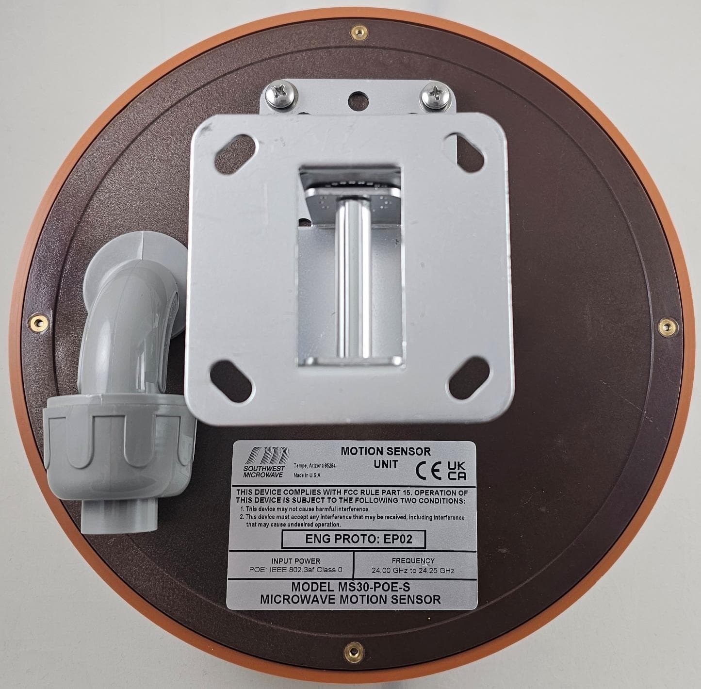
CA6MS30
May 08, 2026Short Range K-Band Transceiver
Equipment Class
DXX - Part 15 Low Power Communication Device Transmitter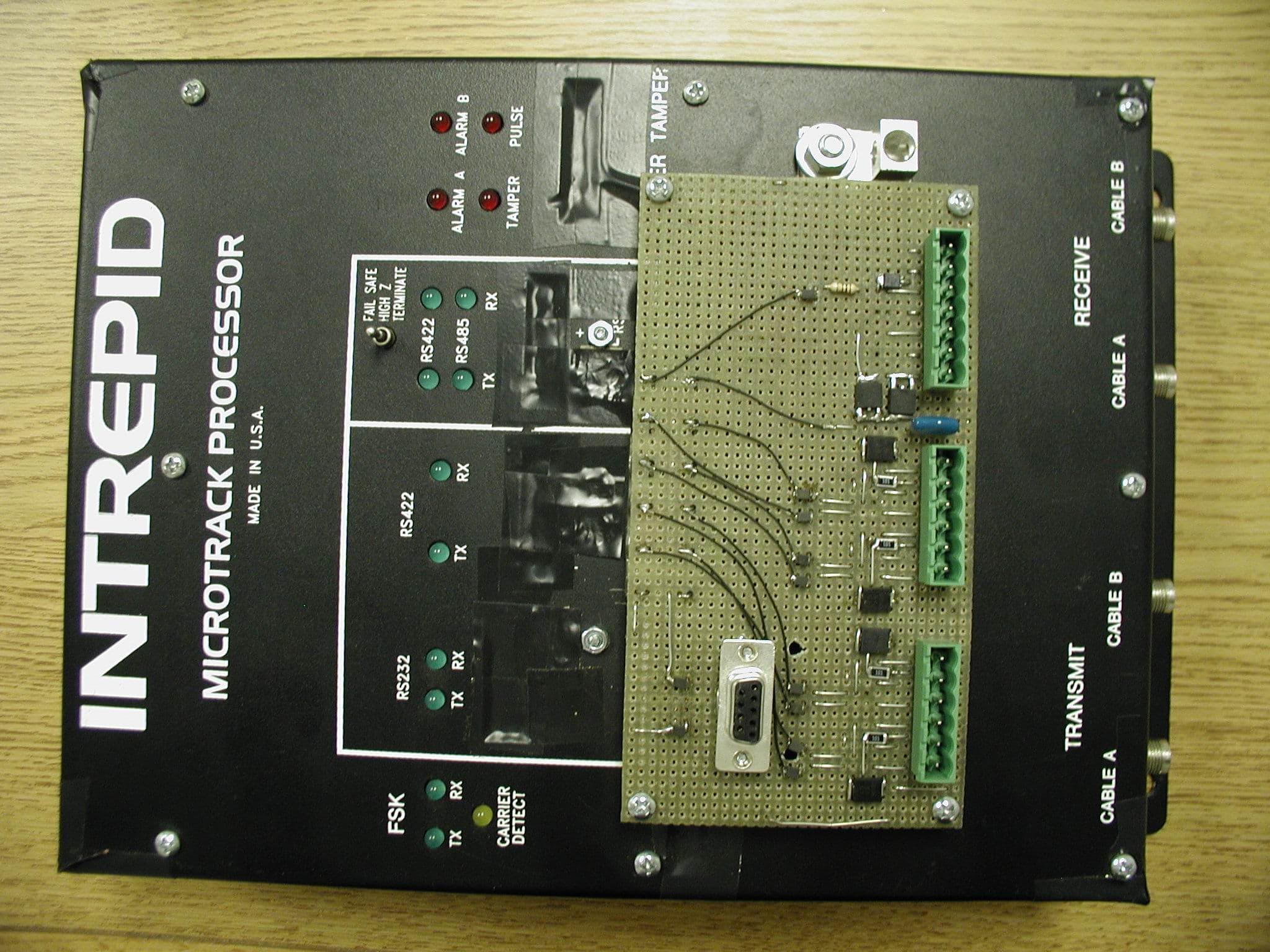
CA6MTP
Mar 06, 2011Perimeter Intrusion Sensor
Equipment Class
FDS - Part 15 Field Disturbance Sensor
CA6380
May 08, 2003Outdoor Microwave Transceiver
Equipment Class
FDS - Part 15 Field Disturbance Sensor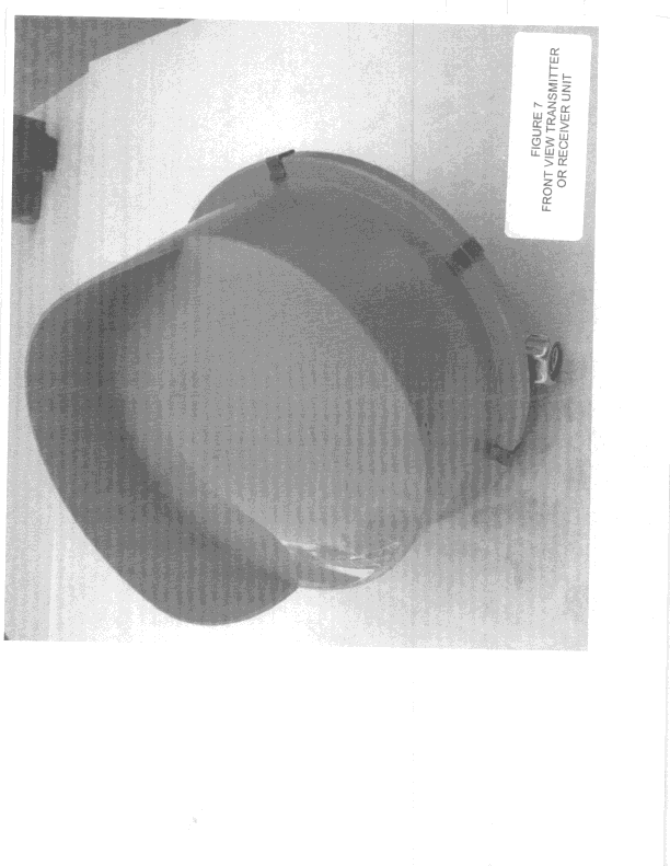
CA6316
Jan 02, 2000FDS - Part 15 Field Disturbance Sensor
Equipment Class
FDS - Part 15 Field Disturbance Sensor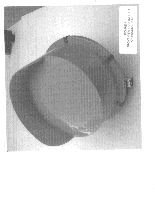
CA6315
Jan 02, 2000FDS - Part 15 Field Disturbance Sensor
Equipment Class
FDS - Part 15 Field Disturbance Sensor