CA6MTPPerimeter Intrusion Sensor
Southwest Microwave Inc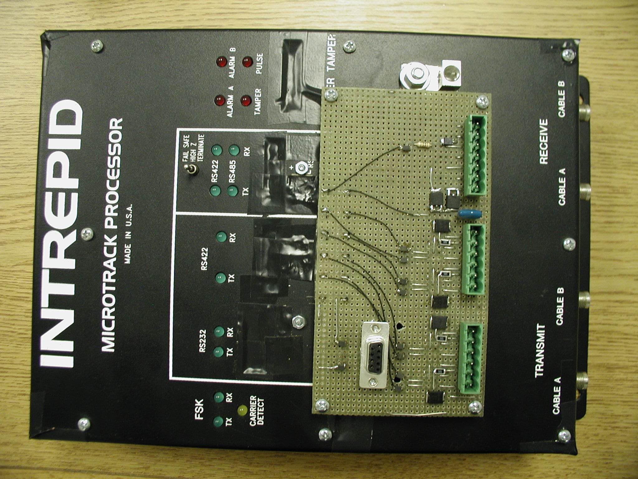
Click to zoom
Application Details
- Equipment Class
- FDS - Part 15 Field Disturbance Sensor
- Date of Grant
- Mar 06, 2011
- Application Purpose
- Original Equipment
- Date of Application
- Apr 19, 2004
- Equipment Note
- Perimeter Intrusion Sensor
- Frequency Range
- 18.20000000 - 25.40000000
- Company
- Southwest Microwave Inc
- Country
- United States
Documents & Files
Document Text
Text extracted from the exhibit documents filed with the FCC. Open a document above to read the original.
Cover Letter(s)
Southwest Microwave, Inc. 9055 South McKemy Street Tempe, Arizona 85284-2946 April 13, 2004 Federal Communication Commission Office of Engineering and Technology Subject: Confidential Files Processing Staff: MicroTrack is a new buried cable outdoor perimeter intrusion detection system. MicroTrack is the first buried cable sensor that is truly site-adaptive and can both detect and locate intruders. MicroTrack is a smart sensor with an integral power and data network. It is patented and it is the first outdoor intrusion detection sensor to use ultra wide band FS/PCM (frequency stepped, phase code modulated) technology. Typical site applications are listed below. . • Military installations • Parked aircraft areas • Government facilities • Nuclear power plants • Electrical substations • Equipment storage areas • Pharmaceutical plants • Correctional facilities • Commercial airports • Oil, gas and petrochemical facilities • R&D facilities • Banking and computer centres • Vehicle parking areas • Communications facilities • Border crossing area Rule section 0.457(a2) and 0.457(d) With many of the applications associated with Military or Homeland Defence, Southwest Microwave, Inc. requests that certain designated files, schematics, operational description and block diagrams be treated as confidential. A technically sophisticated terrorist might design equipment to defeat the intrusion alarm system if the MicroTrack schematics and operational description were available. Although MicroTrack is a patented system, foreign competitors would be advantaged if they had access to the schematics and operational description. Sincerely. James Cheal Director of Research Southwest Microwave, Inc.
Cover Letter(s)
Southwest Microwave, Inc. 9055 South McKemy Street Tempe, Arizona 85284-2946 April 13, 2004 Federal Communication Commission Office of Engineering and Technology Subject: MicroTrack Enclosure Modification. Processing Staff: The external photo of the MicroTrack enclosure has a modification as a result of the preliminary emissions tests. A filter plate was added to suppress harmonics radiated from the power and communication lines. The connectors for these lines were then mounted on a panel external to the main enclosure. This modification will be included in all production units as shown in the Photo titled “MT-Enclosure filter plate”. Sincerely, James Cheal Director of Research Southwest Microwave, Inc.
Cover Letter(s)
Southwest Microwave, Inc. 9055 South McKemy Street Tempe, Arizona 85284-2946 April 13, 2004 Federal Communication Commission Office of Engineering and Technology Subject: Test Site: Processing Staff: The MicroTrack sensor is designed as a low power unlicensed sensor compliant with 15.209 over the frequency band of 18.2 MHz to 25.4 MHz. Paragraph 15.31 suggests an open field site be used for field strength measurements whenever possible. Contract test facilities that conform to 2.948 do not have the space required to bury 200 meters of leaky cable in a straight line; therefore the intentional radiation emission testing was performed at Southwest Microwave, Inc. Maricopa test site. This site as shown in the test setup photos is a level open 31acre field with more than 30 meters access in the area surrounding the 200 meters of radiating cable. The open field site is believed to provide the most accurate data to show compliance with 15.209. The alternative is the conduct the tests at three different sites that can be demonstrated to be typical. Typical user sites may have tall fences or building that serve to contain the field and cause lower levels of field strength at 30 meters. The data recorded at the Maricopa test site for cables buried at 6 inches, 9 inches and on the surface of the ground clearly shows compliance with 15.209 and is believed to provide an accurate representation of the maximum field strength that can be expected from the MicroTrack Perimeter Intrusion Sensor. Sincerely. James Cheal Director of Research Southwest Microwave, Inc.
External Photos
11.16 1.30 0.75 0.875 0.438 0.375 8.51 13.21 MICROTRACK PROCESSOR FILTER PLATE
External Photos
11.16 1.30 0.75 0.875 0.438 0.375 8.51 13.21 MICROTRACK PROCESSOR FILTER PLATE
Test Report
DESCRIPTION OF SOUTHWEST MICROWAVE TEST SITE Southwest Microwave, Inc. purchased 31.7 acres of vacant flat desert land in Pinal County, Arizona for the purpose of engineering and compliance testing of Microtrack and other intrusion detection products. The precise location is given in Fig 1 Fig 1 The site is level desert area with scattered low growing brush as shown in Fig 2. A 10 x 20 foot trailer for storing test equipment and providing a source of AC power is located in the southwest corner of the property. The only other buildings are a farmhouse and water tank over 500 meters west of Hartman Road. The soil is sandy and dry. Measured conductivity is .3 to .5 mS/meter when soaked with water and below .01 mS/ meter when dry. Two pairs of leaky cables are buried in the locations as shown in Fig 1. The photo in Fig 3 is taken near the end of buried cable number 1. The tall trees and the water tank beyond Hartman Road are visible in the top of the picture. Fig 2 Fig 3
Test Report
1 MICROTRACK TEST REPORT Applicable Standards Part 15 of Title 47 of the code of Federal Regulations Paragraphs 15.31, 15.35, 15.205, 15.209 Part 2 of Title 47 Paragraphs 2.948 List of Measuring Equipment ARA model ALA-130/RS Calibrated Loop Antenna Agilent Technologies model E7402A Spectrum Analyzer Calibration Certificates of calibration are included in the Test Setup Photo file. 2 TEST SITE The test site with the cable locations are shown in Fig 1. Fig 1 MEASUREMENT PROCEDURE Microtrack is a low power intrusion detection system. It requires two pairs of 200 meters of radiating cable buried 6 to 9 inches below the surface of the ground. Testing at the typical contract test facility that conforms to Title 47 Part 2 paragraph 2.948 is not feasible due to space limitations. Southwest Microwave, Inc. purchased 31.7 acres of vacant flat desert land in Pinal County, Arizona (Fig 1) for the purpose of engineering and compliance testing of Microtrack and other intrusion detection products. Radiation measurements are made on both buried and unburied cable to determine the maximum field strength possible. Although the Microtrack Sensor is designed and specified only as buried cable system, it is important to know if the system is still in compliance if it is not buried but on the surface of the ground. 3 Measurements of the field strength are made with a calibrated shielded loop antenna (ARA Model ALA-130/RS) and a spectrum analyzer (Agilent Technologies Model E7402A). The Model E7402A was specifically designed by Agilent for FCC and ETSI compliance testing. The loop antenna is mounted on a plastic PVC frame to maintain a constant height above the ground. Measurements are taken at 2.5 and 10 meter intervals along a line parallel and 3 meters from the cable. The data, in the form of a spectrum analyzer screens are recorded on a floppy disk and transferred to a CD for a permanent record. This series of measurements reveals the maximum field strength where data on a line perpendicular to the cable is recorded at one meter intervals out to a distance of 30 meters. Height data is also recorded up to 4 meters high at positions where the field strength is at a maximum. A standard test setup is stored on the Spectrum Analyzer “C” directory for which the peak detector is set for 9 KHz bandwidth and the correction factors for the calibrated loop antenna and the cable losses are included. Field strength in dbμV/m is then read directly from the spectrum analyzer screen. Peak detection was used since quasi-peak measurements are much slower to record. Approximately 400 spectrum analyzer screens (one for each data point) were recorded to arrive at the electro-magnetic field profile for each of the three leaky cables. Transmitted power is limited to 63 mw by fixing the peak to peak voltage at 5 volts on the power amplifier feeding the leaky cable. Each 200 meters of cable receives power 50% of the time. The leaky cables are designed for a coupling loss of 63 db as measured from the transmitter input to the cable and the power received by a standard calibrated antenna located 3 meters from the cable. Transmitter power = 63 mw = 10*log (63) = 18 dbm This value is confirmed by measurement shown in Fig 3 for a 5 volt cw source at 25 MHz. Peak values of the MICROTRACK transmitter with the four frequency phase modulated software are measured at 10.68 dbm (Fig 2). The maximum field strength measured at 3 meters from the buried cable is 55 dbμV. The relationship of dbμV and dbm is: dbμV=107+Pdbm Transmitter Voltage =117 dbμV Received Voltage = 55 dbμv Coupling loss (db) = Transmitter voltage (dbμv) –Receive voltage (dbμv) at 3 meters from the cable. Coupling loss = 62.68db (voltage) 4 Fig 2 Fig 3 1 RADIATED EMISSION TESTS Field strength data were taken as described in the PROCEDURES section. Three pairs of leaky cables were measured., one pair buried 6 inches (15.24 cm) below the surface, one pair buried 9 inches (22.86 cm) below the surface, and one pair on the surface of the ground. A diagram of the test setup is shown in Fig 4. The primary application for intrusion detection will require burial beneath the surface, which will attenuate the field strength due to the conductivity of the soil. The recorded data show the buried cable has significantly lower field strength compared to cable on the surface. The maximum field strength of the surface cable however is below the limit of 30μVolts/meter at 30 meters specified in Part 15 Paragraph 209. Vertical and horizontal polarization is recorded for each data position. The loop antenna is the orthogonal dual of a dipole and the vertical E field is measured with the plane of the loop parallel to the ground and the horizontal polarization with plane of loop perpendicular to the ground. The tests were conducted with modified sweep as described in the ‘OERATIONAL DESCRIPTION”. The linear sweep function has been turned off and replaced with four discrete frequencies. The phase code modulation is still in place. The spectrum is shown in Fig 3. Measurements were made with a peak value in a 9 KHz detection bandwidth. Although Quasi-peak reading is allowed and would yield lower values, peak reading is much faster. This is a major issue with nearly 400 data points for each cable. Soil Conductivity at the test site has been measured at .3 to .5 mS/meter with low moisture content. When the soil is dry, the conductivity was below the .01 mS/m sensitivity level of the test instrument (PET 2000, Dual Purpose EC Meter). Conductivity and dielectric constant of the soil increases with moisture and cause greater attenuation of the surface wave. The tests conducted in dry sandy soil may then be considered as worst case maximum with respect to radiation from the buried cable BURIED CABLE These tests were conducted with a pair of 205 meter leaky cables spliced to 20 meters of shielded lead-in cable buried 6 inches below the surface of the ground. The lead-in cables are used to connect both the …
Text truncated - open the document above for the full version.
Test Report
TEST EQUIPMENT List of Measuring Equipment ARA model ALA-130/RS Calibrated Loop Antenna Agilent Technologies model E7402A Spectrum Analyzer Electro-Metrics Model EM-6917 Biconical Log Periodic Antenna Calibration Certificates of calibration are included for the listed measuring equipment. Fig 1 Fig 2
Test Report
HARMONIC EMISSIONS Harmonic emissions measurements were performed by a certified testing facility: M. Flom Associates Inc. 3356 N. San Marcos Pl., #107 Chandler, AZ 85224-1571 Tel. 480 926 3100 Fax. 480 926 3598 This testing was for the radiation from the Microtrack Processor with communication and power cables attached. Photos of the M. Flon Associates are in the Test Setup file. Additional testing was performed at Southwest Microwave, Inc. for spurious and harmonic emissions directly from the transmitter and also from the radiating cable. Fig 1 shows a measurement with the spectrum analyzer connected to the TNC port of Microtrack transmitter. A 5 th order elliptic filter connected to the transmitter final amplifier attenuates all harmonics above 30 MHz. The second harmonic is 20 db below the fundamental and all other harmonic and spurious 50 db lower. Fig 1 Fig 2 is the same as Fig 1 with frequency sweep extended to 1GHz. Fig 2 The low levels of the harmonic and spurious signals from the transmitter output port is not expected to cause any measurable radiation 3 meters from the leaky cable. The coupling value from the transmitter to a point 3meters from the cable at the fundamental was measured at –63 db. The second harmonic as radiated from the leaky cable is expected to be: From Fig 1 -20 db Coupling loss -63 db Loss 3 meters to 30 meters -40 db Total 123 db below the transmitter power Additional measurements were made at the Southwest Microwave, Inc. Maricopa test site. The loop antenna used for the fundamental radiation from the buried cable is not calibrated above 30 MHz. An Electro-Metrics Model EM-6917 log periodic antenna, calibrated from 30 MHz –1000 MHz was used for the harmonic measurements. The antenna was placed 3 meters perpendicular to the cable and at 30 meters from the leaky cable input where the maximum fundamental was observed. Fig 3 is a typical screen. No harmonics are observed. The large signals are the local television and FM radio stations. The red and blue markers indicate where the harmonics from the Microtrack Processor would appear if they were visible above the noise level. Fig 3 Extending the spectrum analyzer sweep to 1 GHz also shows only local television and FM radio signals. The antenna is not calibrated below 30 MHz. Fig 4
Test Report
Harmonic Emissions Test Report Preliminary testing for harmonic emissions on the Microtrack Processor Module (CA6MTP) was conducted at Southwest Microwave and appropriate changes were incorporated to insure compliance with Part 15.209 of the Commissions Rules. An outside testing laboratory was contracted to verify the SMI tests and to perform official testing to the rules. Testing was performed on a preproduction Processor Module. Testing was performed on an FCC approved 3 meter test range. The certified testing facility was: M. Flom Associates Inc. 3356 N. San Marcos Pl., #107 Chandler, AZ 85224-1571 Tel. 480 926 3100 Fax. 480 926 3598 The emission tests were performed per 15.209 for the processor. Transmit and receive ports were connected to matched loads through 3 meters of specified lead-in cable (SMI P/N 02A15909-A01). The loads simulated the MTC 400-XXX coupled cables. Traffic was simulated on each I/O line to insure worst case emissions. The band was searched from the lowest clock frequency in harmonic steps to 1 GHz. Both the horizontal and vertical planes were searched from 1 to 4 meters. A copy of the following is attached: 1.0 Contractor Letter 2.0 Test Data – Emissions 3.0 Pictures of the 3-meter Test Site The result of the testing is shown on the attached report and no signals were found which exceed the specification. Approved By: Date: March 17, 2004 Title: Vice President, Engineering
Test Report
Southwest Microwave, Inc. 9055 South McKemy Street Tempe, Arizona 85284-2946 June 11, 2004 Federal Communication Commission Office of Engineering and Technology Attention: Andrew Leimer Re: FCC ID CA6MTP Correspondence Reference Number: 26974 731 Confirmation Number: EA669666 Southwest Microwave has a different interpretation of section 15.31(d.) It clearly states “Field strength measurements shall be made to the extent possible, on an open field site”. This is precisely what we did. It is certainly possible to bury and test leaky cable performance on an open field site as described in the referenced application. 31 acres of flat desert land should qualify as an open field site. We believe the open field tests are preferable to installation sites for the following reasons. Many installation sites that can be classified as typical, will have chain link fences and large buildings which will block the field inside the 30 meter test distance and result in a lower value than would be measured at the open field site. Until a large number of systems are installed, how can we demonstrate the three chosen installation are really typical? We understand the for carrier current systems or for leaky cable systems that are part of the internal wiring of a building, there is no other alternative to the three site testing, but for buried cable, measurements can be done on an open field site. Section 15.31(d) also states that “In the case of equipment for which the measurements can be performed only at the installation site”. This provides for alternative measurements at installation sites but does not apply to the Southwest Microwave buried leaky cable system as we have shown it can done on an open field site. We performed three separate tests at the open field site to provide more detailed performance characteristics of the leaky cable. One cable was buried at 6 inches, another at 9 inches and the third on surface of the ground. We specify system performance only with the cable buried 6 to 9 inches below the surface. We tested the cable on the surface only to determine the worst case condition with respect to the maximum radiation. The attenuation due to the conductivity of the soil will always cause lower field strength. Our tests indicate a decrease of more than 10 db of the maximum field strength between the surface mounted cable and buried cable at a 6 inch depth. The data we presented in the application provides an accurate profile of the surface wave established by the leaky cable. It is consistent with published data on leaky cable although we have found very little published that matches the same frequency range Sincerely. James Cheal Director of Research Southwest Microwave, Inc.
Test Report
MICROTRACK TEST REPORT #2 INSTALLION SITE #2 Installation address: 3551 Stonecrest Road Woodlawn, Ontario Canada KOA 3M0 Site Description The site is a level fenced area 140 x 300 feet. It can be considered as representative of an area within a correctional facility. The cables were buried in October, 2003 and system testing continued through the winter and spring of 2004. Parallel Tests Data for the parallel test is given in Fig 1. The maximum field strength is from 6 to 10 meters from the lead-in cable. Perpendicular tests were done at this point. Vertical tests were not recorded at this location. Tests at the Maricopa site show little or no change between 1 and 4 meters of vertical position. This is to be expected since 4meters is less than one half wave length at frequency being transmitted. Buried cable 9" deep 5' spacing, software FCC Loop antenna 5 meter from cable, 1 m above ground) O n tario S ite 0 10 20 30 40 50 60 70 80 90 10 0 -20020406080100120140160180200220 Position (Parallel to the cable,meters) Horizontal Vertical Fig 1 Fig 2 The data recorded on a line perpendicular to the leaky cable shows the field strength drops below the 15.209 limit of 30 uV/m at less than 10 meters from the cable. This is just inside the fence line. Only low level signals (below 15.209) were detected outside the fence. System tests also show no detection when the fence is vibrated. This confirms that radiation from the leaky cable does not illuminate the fence 10 meters away. Buried Cable, 9" deep, 5' spacing, software FCC 8 me te rs from le a d in Ontario Site 0 10 20 30 40 50 60 70 80 01234567891011 121314151617181920 21 22 23 24 25 26 27 28 29 30 Position (Perpendicular to the cable,meters) Horizontal Vertical FCC limit Part 15.209 Noise floor Photos of the Ontario Installation Site. 3551 Stonecrest Road, Woodlawn, Ontario
Test Report
MICROTRACK TEST REPORT # 3 INSTALLION SITE #3 Installation address: 9055 S McKemy Street Tempe, Arizona 85282 Site Description This installation is just inside the property boundary line. The leaky cable is buried to a depth of 9 inches between two chain link fences for the first 100 meters from the transmitter. The fences are separated by about 30 meters. The cable makes a right angle turn beyond 150 meters and runs for another 50 meters next to a low masonry wall (4ft high). The parallel measurements are recorded 3 feet from the cable (Fig1). The first peak in field strength occurs between 5 and 10 meters from the transmitter. Radiation was not detected outside the fence. The fences prevents any useful data perpendicular to the cable so the first peak beyond the fence line is at 105 meters from the transmitter. This peak is only 3 db less and provides more meaningful data out to 15 meters where the field strength falls below 30 uV/m. Fig 1 Fig 2 Buried Cable 9" deep, 5' spacing, software FCC Loop antenna 3 meter from cable, 1 m above ground Tempe, AZ 0.00 10.00 20.00 30.00 40.00 50.00 60.00 -5.015.035.055.075.095.0115.0135.0155.0175.0195.0 Position (Parallel to the cable,meters) Voltage (dbuV/m) Hor izont al Vertical Buried Cable 9" deep, 5' spacing, software FCC, Loop antenna, 105 meters from lead in splice, 1 m above ground. Tempe AZ Installation 0.00 10.00 20.00 30.00 40.00 50.00 60.00 70.00 0123456789101112131415161718192021222324252627282930 Position (Perpendicular to the cable,meters) Voltage (dbuV/m) Hor izont al Vertical FCC limit 15.209 Tempe installation, parking lot
Test Setup Photos
1 DESCRIPTION OF SOUTHWEST MICROWAVE TEST SITE Southwest Microwave, Inc. purchased 31.7 acres of vacant flat desert land in Pinal County, Arizona for the purpose of engineering and compliance testing of Microtrack and other intrusion detection products. The precise location is given in Fig 1 Fig 1 The site is level desert area with scattered low growing brush as shown in Fig 2. A 10 x 20 foot trailer for storing test equipment and providing a source of AC power is located in the southwest corner of the property. The only other buildings are a farmhouse and water tank over 500 meters west of Hartman Road. The soil is sandy and dry. Measured conductivity is .3 to .5 mS/meter when soaked with water and below .01mS/ meter when dry. Two pairs of leaky cables are buried in the locations as shown in Fig 1. The photo in Fig 3 is taken near the end of buried cable number 1. The tall trees and the water tank beyond Hartman Road are visible in the top of the picture. 2 Fig 2 Fig 3 3 Description of the Test Structures The equipment measures the field strength of the emissions from the leaky cable. A PVC frame holds the calibrated loop antenna at constant height above the ground and can be easily moved. The spectrum analyzer has the DC power option and is mounted along with a 12 volt battery on a moveable cart. This equipment is used to map the field near the ground level and is shown in the photo titled “Field Measurement Mobile Test Equipment”. Measurements at heights up to 4 meters used the equipment shown in the photo titled “Field Height Measurement Fixture”. This is also constructed from PVC tubing to minimize distortion of the emitted fields. The loop antenna can be raised, lowered and rotated for different polarizations as required
Test Setup Photos
Ontario Installation Site # 2, more photos. Microtrack processor Mounted on the fence. Trenches for lead-in cables to the Microtrack Processor.
Test Setup Photos
Photos of Tempe, AZ Installation Site # 3 MicroTrack processor, Tempe Installation. Buried cable between two fences.
Test Setup Photos
Tempe, AZ Installation (more Photos) Buried cable in landscaped perimeter Buried cable, north wall
Contact Information
Applicant
Edward J Foley(Vice President Engr.)
Technical Contact
Southwest Microwave, Inc.James Cheal
[email protected](480) 783 0201
9055 South McKemy Street · Tempe, Arizona · United States
Test Firm
M. Flom Associates, Inc.Morton Flom
Technical Specifications
| # | Rule Parts | Frequency Range | Power Output |
|---|---|---|---|
| 1 | 15C | 18.2 MHz - 25.4 MHz | 63.00 mW |
Other Applications from Southwest Microwave Inc
CA6MS30
May 08, 2026Short Range K-Band Transceiver
Equipment Class
DXX - Part 15 Low Power Communication Device Transmitter
CA6330
Sep 12, 2012Digital Microwave Field Disturbance Sensor
Equipment Class
FDS - Part 15 Field Disturbance Sensor
CA6380
May 08, 2003Outdoor Microwave Transceiver
Equipment Class
FDS - Part 15 Field Disturbance Sensor
CA6316
Jan 02, 2000FDS - Part 15 Field Disturbance Sensor
Equipment Class
FDS - Part 15 Field Disturbance Sensor
CA6315
Jan 02, 2000FDS - Part 15 Field Disturbance Sensor
Equipment Class
FDS - Part 15 Field Disturbance Sensor