CA6380Outdoor Microwave Transceiver
Southwest Microwave Inc
Click to zoom
Application Details
- Equipment Class
- FDS - Part 15 Field Disturbance Sensor
- Date of Grant
- May 08, 2003
- Application Purpose
- Original Equipment
- Date of Application
- Mar 09, 2003
- Equipment Note
- Outdoor Microwave Transceiver
- Frequency Range
- 24075.00000000 - 24175.00000000
- Company
- Southwest Microwave Inc
- Country
- United States
Documents & Files
Document Text
Text extracted from the exhibit documents filed with the FCC. Open a document above to read the original.
Users Manual
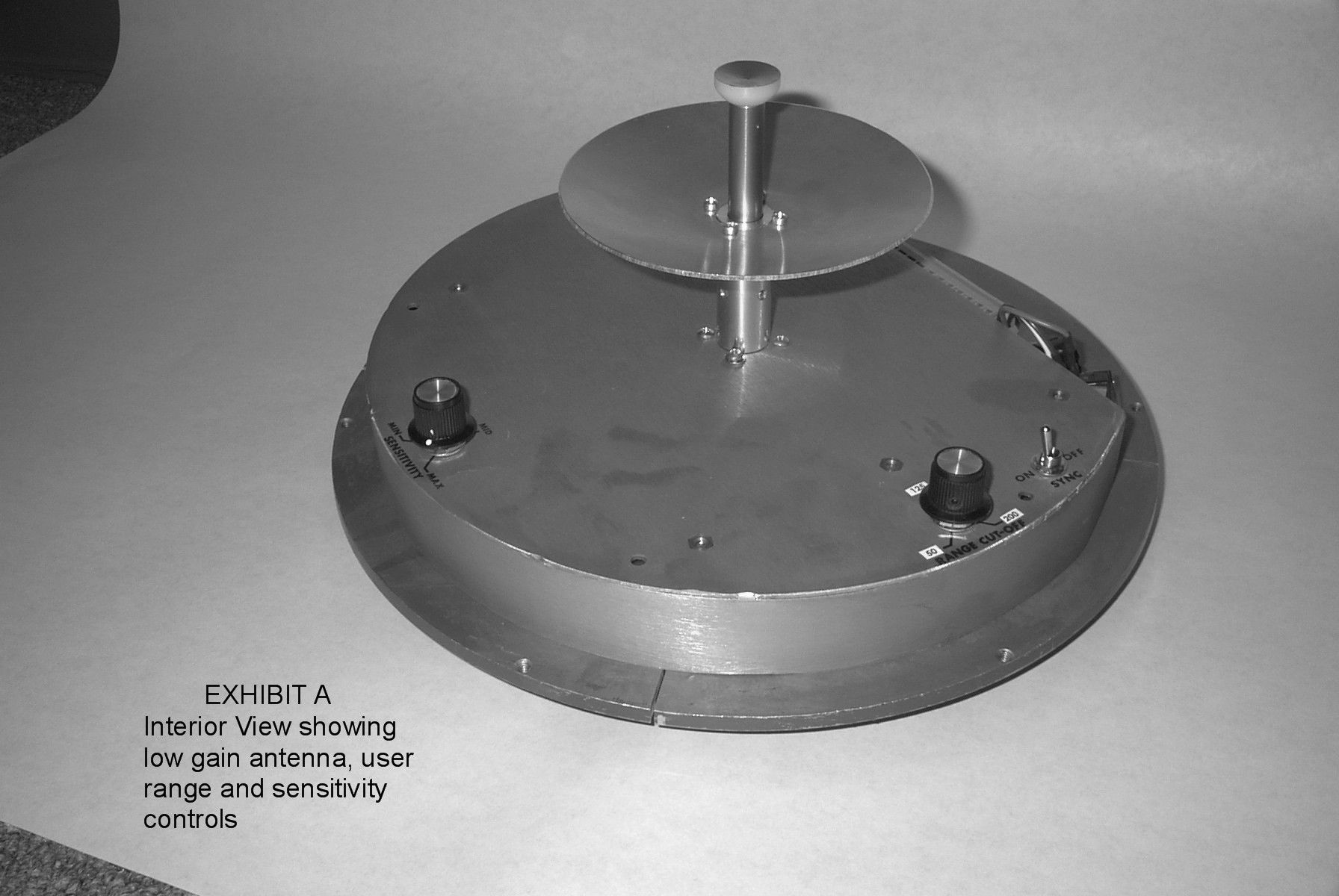
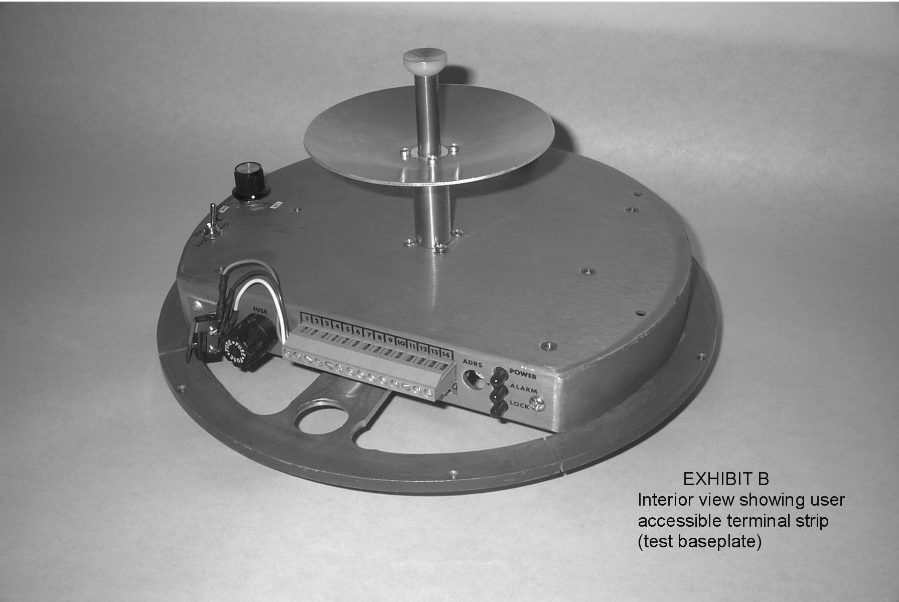
Southwest Microwave, Inc. Security Systems Division TECHNICAL MANUAL MODEL 380 OUTDOOR MICROWAVE TRANSCEIVER SOUTHWEST MICROWAVE, INC. 9055 S. McKemy Street Tempe, Arizona 85284-2946 TEL (480) 783-0201 FAX (480) 783-0401 2 TABLE OF CONTENTS INTRODUCTION ................................................................................................................................................................. 3 OPERATION ......................................................................................................................................................................... 3 THEORY ............................................................................................................................................................................... 4 SPECIFICATIONS ................................................................................................................................................................ 7 SITE PREPARATION .......................................................................................................................................................... 8 LOCATION OF TRANSCEIVERS ...................................................................................................................................... 9 MULTIPLE UNIT INSTALLATIONS .............................................................................................................................. 11 MOUNTING ........................................................................................................................................................................ 13 POWER WIRING ............................................................................................................................................................... 14 CONNECTIONS ................................................................................................................................................................. 15 ALIGNMENT AND TEST ................................................................................................................................................. 16 PREVENTATIVE MAINTENANCE ................................................................................................................................ 17 OPTIONAL EQUIPMENT ................................................................................................................................................. 18 WARRANTY AND RETURN INFORMATION .............................................................................................................. 18 NOTE: This manual is for Models 380 and 380-33453March 2003 3 INTRODUCTION_____________________________________________________________ Model 380 Outdoor Microwave Transceiver incorporates state-of-the-art technology and innovative electronic circuitry to provide reliable detection in the outdoor environment. A unique continuously variable Range Cutoff (RCO) circuit allows maximum detection range to be established independently of object size, thereby eliminating alarms caused by large objects beyond the desired detection range. Model 380 is also equipped with Zero Range Suppression (ZRS) circuitry that reduces sensitivity to small objects very close to the transceiver so that alarms due to rain or vibration are minimized. Model 380 includes synchronization and addressing circuitry that enables simultaneous operation of up to 16 units without mutual interference. The Model 380 is also built with staggered RF frequencies (Channel A and B) to help minimize mutual interference. Model 380 may be mounted to a variety of posts or wall structures by means of its universal-mounting bracket. A military style multi-pin connector, at the rear of the transceiver housing, permits remote monitoring and diagnostics of critical system parameters. OPERATION_________________________________________________________________ Model 380 includes both transmitter and receiver in a single enclosure. The transmitter radiates microwave energy that is reflected back into the receiver by objects within the detection zone. The observed detection zone is established by two controls - Sensitivity and Range. Figure 1A shows the zone of detection (horizontal pattern) for an upright man when Model 380 is mounted 2.5 feet (.75 meters) above smooth earth with its beam oriented parallel to the ground. The Range control adjusts the maximum range of the system and the Sensitivity control primarily adjusts the width. Figure 1B shows the vertical pattern for the same configuration, note that the detection zone does not extend into the small area immediately under Model 380. This area varies with the Sensitivity setting as shown in Figure 2. In order to provide uninterrupted detection of a man walking or crawling on his hands and knees, an additional unit must provide overlap protection such as shown in Figure 3. Detection of a man crawling "commando-style" may require additional overlap or special site preparation. Sensitivity should always be adjusted to the absolute lowest setting that will meet site security requirements. Excessively high sensitivity may cause nuisance alarms from high grass, small birds or windblown debris in the detection zone. Model 380 responds to any motion within the detection zone. Figure 1 - Model 380 Detection Pattern SENSITIVITY MINIMUM SENSITIVITY MAXIMUM ACTIVE DETECTION PATTERN CUTOFF RCO CONTINUOUSLY VARIABLE 50' MIN 200' MAX (3.4m) (15m) (122m) A) HORIZONTAL PATTERN B) VERTICAL PATTERN 15' MAX PATTERN HEIGHT 4 THEORY_____________________________________________________________________ A microwave transceiver transmits microwave energy into the detection zone, and objects in the zone reflect energy back to its receiver. Whenever an object is moving, the Doppler effect shifts the frequency of its reflection and the transceiver generates an alarm whenever it detects a frequency shift in the reflected energy. The size o…
Text truncated - open the document above for the full version.
Cover Letter(s)
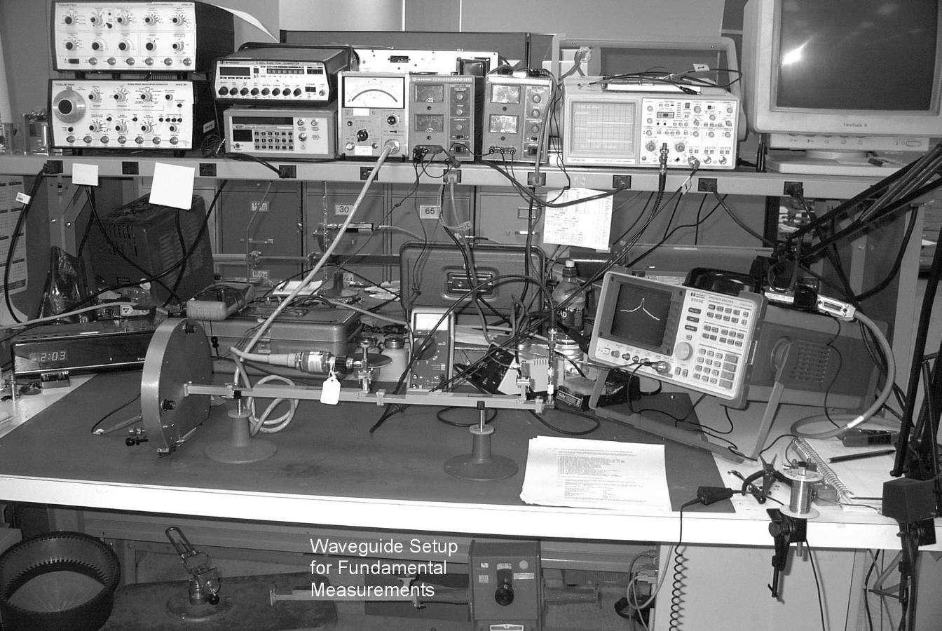
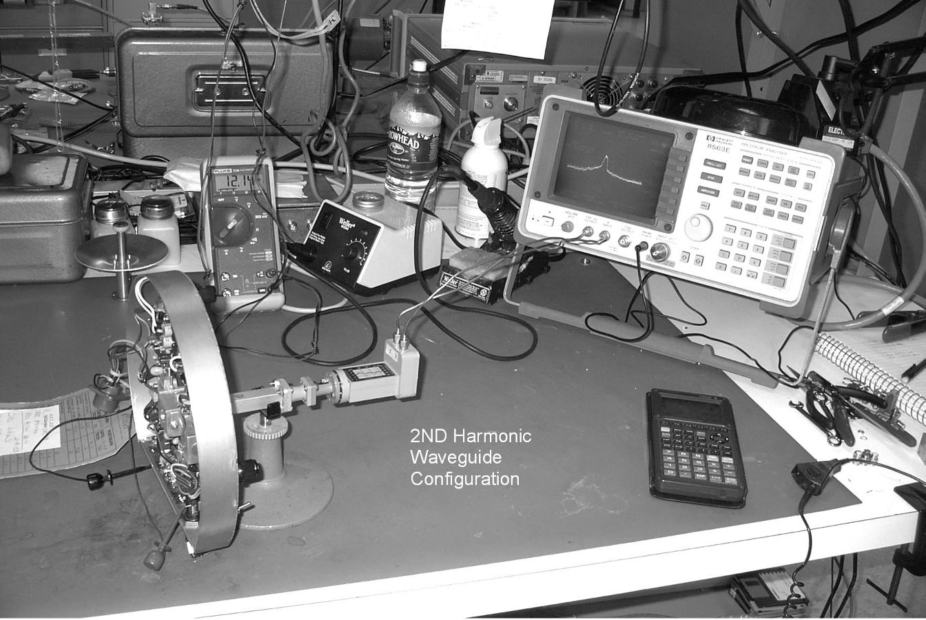
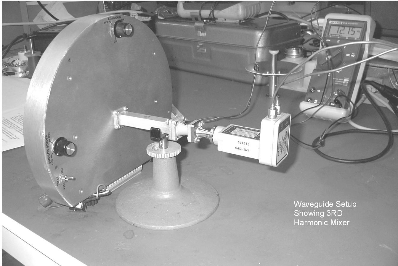
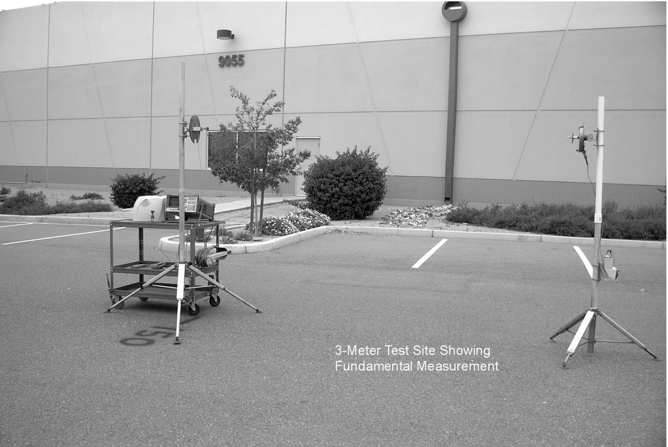
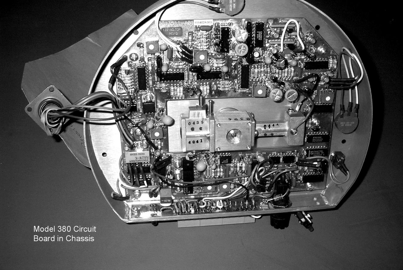
Addendum to FCC Submittal FCC ID: CA6380 Form 731 Confirmation Number: EA 454545 To: Federal Communications Commission Office of Engineering and Technology Attn.: Linda Elliot Ref.: Correspondence Number 24989 FCC ID CA6380 731 Confirmation Number EA454545 Date: April 9, 2003 From: Edward J. Foley Southwest Microwave, Inc. Per your request, Southwest Microwave submits the following documents as an addendum to our original submittal of March 10, 2003. The items contained in this submittal are the following: Document Description Type File 04D13509RevL Complete Schematic PDF 380 Tech Manual Users Manual PDF FCC Report380 Block Diagram and RF Test Report PDF Emissions Low Frequency Emissions PDF Report Pictures PDRM 0003 Waveguide Fundamental JPG Measurement PDRM 0004 2nd Harmonic Mixer JPG PDRM 0007 3rd Harmonic Mixer JPG PRDM 0011 3-Meter Test Site (Fund.) JPG PDRM 0019 3-Meter Test Site (Harm.) JPG PDRM 0021 3-Meter Test Site (Harm.) JPG PDRM 0042 Model 380 Circuit Board JPG We trust that this information will be sufficient to satisfy the submittal requirements. The Model 380 is a high-end security system and the need is urgent. Our primary customers are the military and nuclear power companies. Respectfully submitted, Edward J. Foley Vice President Engineering Southwest Microwave, Inc.
ID Label/Location Info
EXHIBIT E SAMPLE LABEL AND LOCATION ON UNIT
Test Report
EXHIBIT C Model 380 Antenna E Plane Profile Gain 22.36 dB 3 dB Beamwidth 8.13 Deg. -50-45-40-35-30-25-20-15-10 -5 05 -90 -60 -30 0 30 60 90 Angle (Degrees) Relative Amplitude (dBc)
Test Report
EXHIBIT D Model 380 Antenna H Plane Profile Gain 22.44 dB 3dB Beamwidth 7.84 Deg -45-40-35-30-25-20-15-10 -5 05 -90 -60 -30 0 30 60 90 Angle (Degrees) Relative Amplitude (dBc)
Test Report
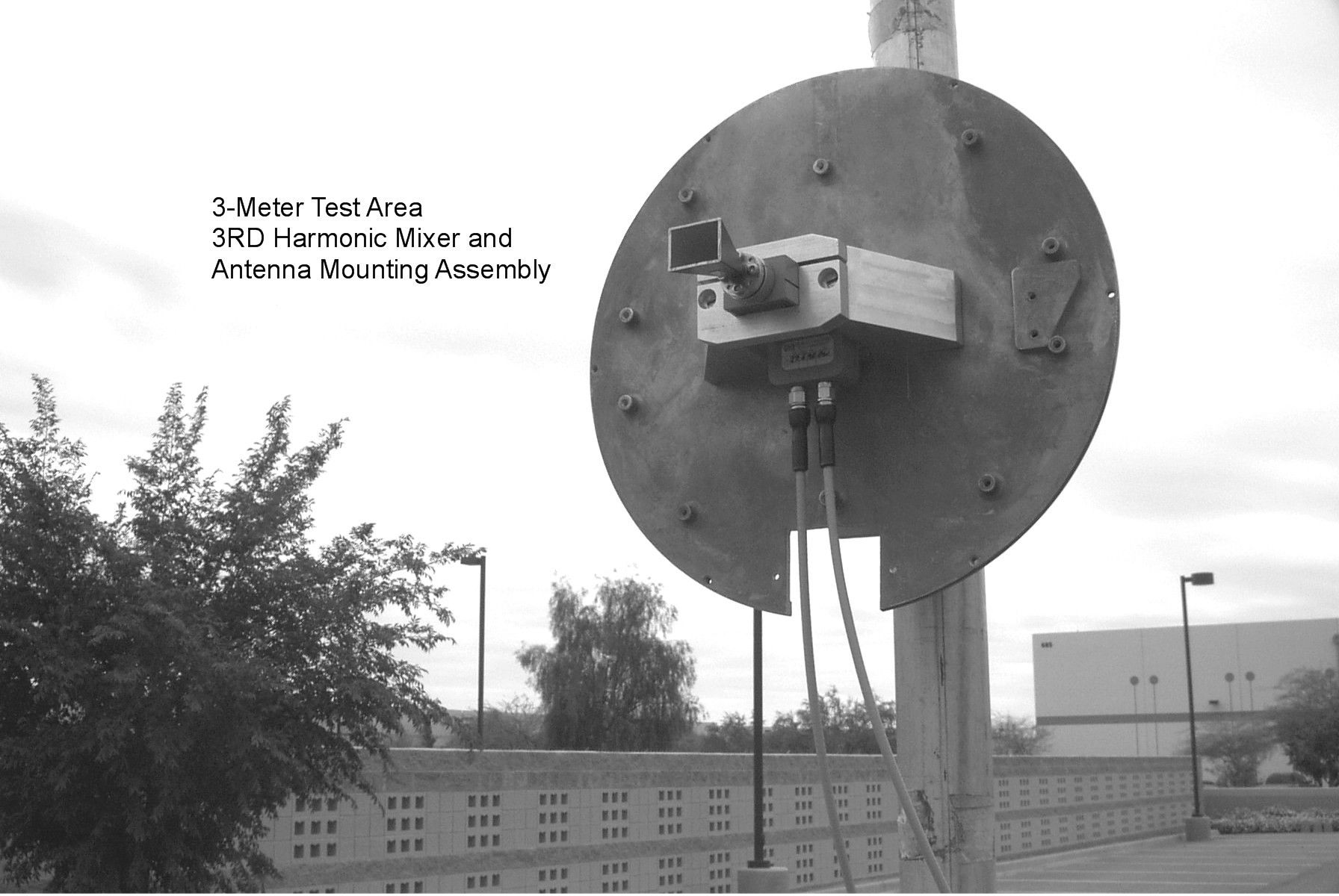
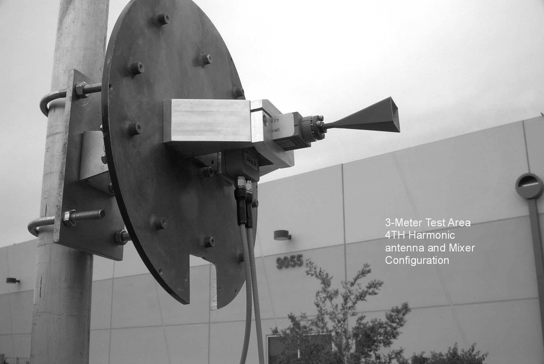
TEST PROCEDURE AND REPORT CONDUCTED AND RADIATED EMISSIONS UNLICENSED INTENTIONAL RADIATOR SOUTHWEST MICROWAVE MODEL 380 31 MARCH 2003 INTRODUCTION This procedure and report was prepared to insure compliance with the requirements of part 15.245 of the Federal Communications Rules and Regulations regarding unlicensed intentional radiators. The procedures outlined herein are based on the October 1, 2001 revision of the Federal Communications Commission Rules and Regulations, Parts 2 and 15. The measurements made herein were performed on a preproduction model of the equipment specified and is considered representative of all production units of this series. The product referenced in this document is a microwave transceiver operating within the frequency band of 24.075 to 24.175 GHz. It is a shorter-range version of the Southwest Microwave Model 385 that was certified under file number 31010/EQU 4-3-3 dated August 13, 1991. All aspects of the two sensors are electrically identical except that model 380 has a lower gain antenna. The Doppler sensor is intended to operate as an outdoor security system and therefore must be certified as an intentional radiator. Because of the low powers involved, RF harmonic measurements were performed directly on the transmitter using a waveguide test set-up and then repeated with an antenna installed on the 3-meter test site. All microwave testing was performed at the Southwest Microwave test site, documentation for which has been filed with the Federal Communications Commission. M. Flom and Associates, Chandler, AZ performed radiation tests per part 15.209 of the commission’s rules. This product utilizes a 4.2-inch diameter parabolic antenna, having a gain of approximately 22.4 dB and a beamwidth of 8.0 degrees (-3 dB) at 24.125 GHz. The modulation signal is comprised of a one-microsecond pulse train operating at a 32-kilohertz repetition rate resulting in a 3.2 percent duty cycle. Alternate pulses are shifted in frequency by approximately 615 kilohertz. BLOCK DIAGRAM Referring to the block diagram shown below, all timing functions are derived from the master clock which is contained within the phase locked loop and is operating at a frequency of 1.024 MHz. The clock is divided down to 1 kHz and coupled to the phase comparator of the phase locked loop. If the system is operated in the master mode the oscillator is free running and provides a 1 kHz clock at the master output terminals. This RS 422 master output can be used to sync up to 16 other units together, providing a unique address to each so that interference between sensors is eliminated. The address is selected by means of a binary switch located in each sensor. The phase-lock loop output is connected to a binary ripple counter which provides a 1 microsecond pulse at a 32 kHz repetition rate and a 32 kHz square wave which is connected to a divide by 2 circuit resulting in two channels at 16 kHz of opposite phase. The one-microsecond pulse is connected to oscillator drive circuit, which provides a minimal voltage change resulting in a small frequency shift on alternate pulses (approximately 615 kHz). The transmitted signal is therefore a continuous pulse train of 1- microsecond pulses at a 32 kHz repetition frequency with alternate pulses shifted by 615 kHz. A certain portion of the transmitted signal is coupled to a detector diode where the pulse envelope is detected, amplified and connected to a leading edge detector circuit. The output of this circuit is a narrow sampling pulse that is positioned from the leading edge in time by means of a user accessible range-cutoff potentiometer. The range cutoff feature prevents signals from being processed beyond the time it takes the RF pulses to intercept the target and return. The receiver channels are alternately switched at a 16 kHz rate coincident with the Fa and Fb frequencies. The two-frequency approach provides Doppler signals whose phase is proportional to range. The sampled Doppler output of each channel is then connected to a difference amplifier, the output of which provides a signal whose amplitude is proportional to the phase difference between the two Doppler signals. The purpose of this circuit is to cancel the effects of rain on the radome. Rain running down the radome causes Doppler signals that are in phase because of the close proximity to the transmitter and are essentially cancelled. The Doppler output of the difference amplifier is amplified after filtering and then connected to a comparator circuit that provides an alarm if the signal amplitude exceeds either threshold. 4 BIT COMP ADDR PLL CTR MASTER OUTPUT SLAVE INPUT 1.0 uSec AMP AMP + - SENS VL ALARM CKTS THRESHOLD LOW-PASS FILTER RCO TIMING RANGE FbFa TX OSC VCO DRIVER Fc FcFd + - LOCK S1 RELAY TB1-6 TB1-7 TB1-8 TB1-4 TB1-5 N.O. COM N.C. COM N.C. ALARM TB1-10 TB1-11 TB1-12 TB1-13 TB1-14 + + - - SUPPLY VCO SUPPLY POWER TB1-9 TB1-1 TB1-2 P1-A POWER P1-D + - P1-B +9V +5V +7V TEST P1-F P1-C P1-E LED LED TAMPER SWITCH TB1-3 N.O. ONE SHOT S2 VH +5V SYNC ONOFF LEADING EDGE DETECTOR VH VL 1.024 MHz Q Q 1 KHz Va Vb Va 32 KHz 31.2 uS Fa Fb 1uS Fa 62.5uS +15dBm Model 380 Block Diagram Divide by 2 Fc Fa Fb Delta F = Fb-Fa = 615 KHz Fc=24.125 GHz Spectrum ALARM LED Avg. Pwr = 0 dBm TABLE OF CONTENTS 1.0GENERAL 2.0SPECIFICATIONS 3.0PERTINENT SPECIFICATIONS 4.0EQUATIONS AND CALCULATIONS 4.1 Field Strength to Received Power 4.2 Conversion Calculations 5.0TEST PROCEDURE 5.1 Test Site 5.2 Test Equipment 5.3 Field Strength and Spurious Emission Measurements 5.4 Radiated Limits 5.5 Conducted Emissions 6.0TEST REPORT 6.1 Certification Test Report 1.0GENERAL The purpose of this test procedure and report is to specify the measurement technique to be used in determining compliance with Federal Communications Commission (FCC) regulations applying to an unlicensed intentional radiator for purpose of certification. 2.0SPECIFICATIONS 2.1Commission Rules & Regulations, Title 47, Parts 15, dated October 1, 2001.…
Text truncated - open the document above for the full version.
Test Report
FCC ID: CA6380 MFA p0340004, d0340008 g0340003: 2003-Apr-08 Tue 13:00:00 FREQUENCY TUNED, MHz FREQUENCY EMISSION, MHz LEVEL, dBuV @ mC.F., dBμV/m@ m 0.0000001.0240004.83315.4020.233 0.0000002.04800012.03315.4027.433 0.0000003.072000-2.03315.4013.373 0.0000004.0960002.47315.4017.873 0.0000005.1200000.49313.5013.993 0.0000006.144000-0.63313.5012.873 0.0000007.168000-0.15313.5013.353 0.0000008.192000-2.43313.5011.073 0.0000009.2160000.18313.5013.683 0.00000010.2140002.14312.7014.843 0.00000011.2640000.84312.7013.543 0.00000012.288000-3.52312.709.183 0.00000013.312000-1.82312.7010.883 0.00000014.3360004.69312.7017.393 0.00000015.36000010.87311.3022.173 0.00000016.3840008.05311.3019.353 0.00000017.4080000.65311.3011.953 0.00000018.432000-0.41311.3010.893 0.00000019.4560000.14311.3011.443 0.00000020.480000-2.3539.407.053 0.00000021.5040006.2739.4015.673 0.00000022.5280000.8439.4010.243 0.00000023.5520000.9539.4010.353 0.00000024.576000-0.9437.506.563 0.00000025.600000-2.8737.504.633 0.00000026.624000-0.3337.507.173 0.00000027.6480005.1837.5012.683 0.00000028.6720001.07310.1011.173 0.00000029.696000-0.37310.109.733 g0340003: 2003-Apr-07 Tue 13:29:00 FREQUENCY TUNED, MHz FREQUENCY EMISSION, MHz LEVEL, dBuV @ mC.F., dBμV/m@ m 0.00000030.7200006.50315.3112.323 0.00000032.7700004.21315.589.763 0.00000034.8200005.02315.8411.043 0.00000036.8600003.45315.809.173 0.00000038.9100006.98315.7313.663 0.00000040.9600003.37315.749.033 0.00000043.0100001.26315.837.153 0.00000045.0600009.57315.8918.753 0.00000047.1040006.85315.3412.873 0.00000049.1500009.64314.8216.713 0.00000051.2000008.10314.5913.633 0.00000053.25000010.06314.5617.023 0.00000055.30000010.78314.5518.473 0.00000057.3400009.93314.5316.713 0.00000059.39000010.90314.5018.623 0.00000067.58000010.53312.8814.813 0.00000069.63200012.20312.4717.123 0.00000071.68000011.24312.1714.813 FCC ID: CA6380 MFA p0340004, d0340008 g0340003: 2003-Apr-07 Tue 13:29:00 FREQUENCY TUNED, MHz FREQUENCY EMISSION, MHz LEVEL, dBuV @ mC.F., dBμV/m@ m 0.00000073.73000011.16311.9014.223 0.00000075.78000016.87311.6326.613 0.00000079.87000012.96311.1216.003 0.00000083.96800017.47311.5928.383 0.00000083.9700008.21311.599.773 0.00000086.01600015.13311.8422.313 0.00000088.06400013.60312.0819.233 0.00000096.25600014.55313.5125.293 0.00000098.30400019.25313.8945.393 0.000000104.4480007.34314.6612.593 0.000000108.5440006.91315.0812.573 0.000000110.5920007.50315.2713.763 0.000000112.6400003.17315.478.553 0.000000114.6880009.88315.6618.923 0.000000116.7360006.26315.8512.753 0.000000118.7840004.54316.0210.673 0.000000120.8320001.39316.217.593 0.000000122.8800009.74316.3820.233 0.000000126.9760006.19316.6013.793 0.000000129.0240008.16316.6617.423 0.000000131.0720004.48316.7211.483 0.000000133.1200002.59316.789.303 0.000000135.1680005.08316.8212.453 0.000000139.2640006.80316.9315.363 0.000000141.3120003.67317.0010.803 0.000000143.3600000.94317.077.953 0.000000145.4080000.08317.147.263 0.000000147.4560006.32317.2215.033 0.000000149.5040004.17317.2911.833 0.000000151.55200011.16317.3526.643 0.000000155.6480006.60317.4715.983 0.000000155.64800011.81317.4729.113 0.000000157.6960005.51317.5314.193 0.000000159.7400007.26317.5817.463 0.000000161.7900001.49317.629.033 0.000000163.8400004.03317.6612.153 0.000000165.8900001.50317.699.113 0.000000167.9400003.24317.7311.183 0.000000169.9800005.54317.7614.623 0.000000174.0800002.86317.8310.833 0.000000176.1300007.64317.9419.013 0.000000178.1800003.96318.1012.683 0.000000180.2200002.95318.2511.483 0.000000186.3700003.61318.5812.873 0.000000188.4200008.04318.7021.733 0.000000190.4600002.66318.8011.833 0.000000198.660000-1.98319.237.293 0.000000202.7500001.39319.4310.993 0.000000210.9400001.87319.7912.113 0.000000212.9920009.65319.8829.963 0.000000215.0400000.40319.9710.443 0.000000217.0880006.13320.0620.393 FCC ID: CA6380 MFA p0340004, d0340008 FREQUENCY TUNED, MHz FREQUENCY EMISSION, MHz LEVEL, dBuV @ mC.F., dBμV/m@ m 0.000000219.1360007.59320.1524.383 0.000000221.1840005.10320.2318.473 0.000000223.2320002.86320.3214.423 0.000000225.2800001.75320.4112.823 0.000000227.328000-2.11320.508.313 0.000000229.3760005.11320.5819.253 0.000000231.4240003.51320.6716.183 0.000000235.5200003.62320.8316.693 0.000000237.5680004.52320.9118.693 0.000000239.6160003.04321.0015.923 0.000000241.6640003.09321.0816.163 0.000000243.7120000.86321.1612.623 0.000000245.7600003.90321.2418.073 0.000000247.8080002.07321.3214.773 0.000000249.8560006.12321.4023.773 0.000000251.9040001.91321.8515.423 0.000000256.0000006.63322.8129.653 0.000000258.0480002.82323.2920.213 0.000000260.0960000.47323.7616.273 0.000000264.1920002.17324.6922.033 0.000000266.2400005.53325.1534.203 0.000000268.2880001.36325.6222.343 0.000000272.3840001.34326.5224.723 0.000000274.4320004.81326.9738.823 0.000000276.4800002.65327.4131.843 0.000000278.5280001.96327.8530.943 0.000000280.5760004.20328.2942.123 0.000000282.6240002.82328.7437.843 0.000000284.6720002.72329.1839.363 0.000000288.768000-0.73330.0529.243 0.000000290.816000-0.16330.5032.893 0.000000292.8640001.68330.9342.713 0.000000294.9120001.84331.3545.663 0.000000296.9600002.72331.7853.093 0.000000299.0080003.62332.2061.803 0.000000303.1040004.00320.4416.673 0.000000307.2000003.23320.7415.793 0.000000311.2960003.16321.0316.203 0.000000315.3920004.03321.3418.563 0.000000319.4880001.03321.6313.583 0.000000323.5840002.25321.9216.163 0.000000327.680000-0.38322.2012.333 0.000000331.7760000.00322.4813.303 0.000000335.8720001.32322.7515.983 0.000000339.9680001.19323.0116.223 0.000000344.0640006.04323.2829.243 0.000000348.1600002.86323.5420.893 0.000000352.2560004.74323.826.733 0.000000356.3520002.82324.0522.053 0.000000360.4480001.52324.319.543 0.000000364.540000-1.71324.5213.823 0.000000368.6400002.14324.7422.083 0.000000372.7400003.45324.9526.303 FCC ID: CA6380 MFA p0340004, d0340008 FREQUENCY TUNED, MHz FREQUENCY EMISSION, MHz LEVEL, dBuV @ mC.F., dBμV/m@ m 0.000000376.830000-0.82325.1616.483 0.000000380.930000-0.98325.3616.563 0.000000385.0200000.99325.5721…
Text truncated - open the document above for the full version.
Contact Information
Applicant
Edward J Foley(Vice President Engr.)
Technical Contact
Southwest Microwave Inc.Edward J Foley
[email protected](480) 783-0201
9055 S. McKemy St. · Tempe, Arizona · United States
Non-Technical Contact
Southwest Microwave Inc.Micheal A Esparza
[email protected](480) 783-0201
Test Firm
Southwest Microwave Inc.Edward Foley
Technical Specifications
| # | Rule Parts | Frequency Range | Power Output |
|---|---|---|---|
| 1 | 15.245 | 24.07 GHz - 24.18 GHz | - |
Other Applications from Southwest Microwave Inc
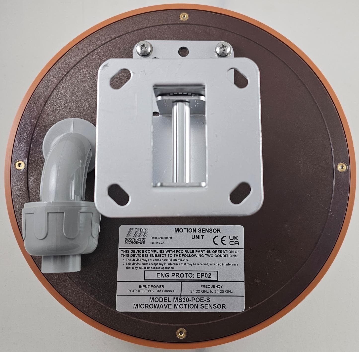
CA6MS30
May 08, 2026Short Range K-Band Transceiver
Equipment Class
DXX - Part 15 Low Power Communication Device Transmitter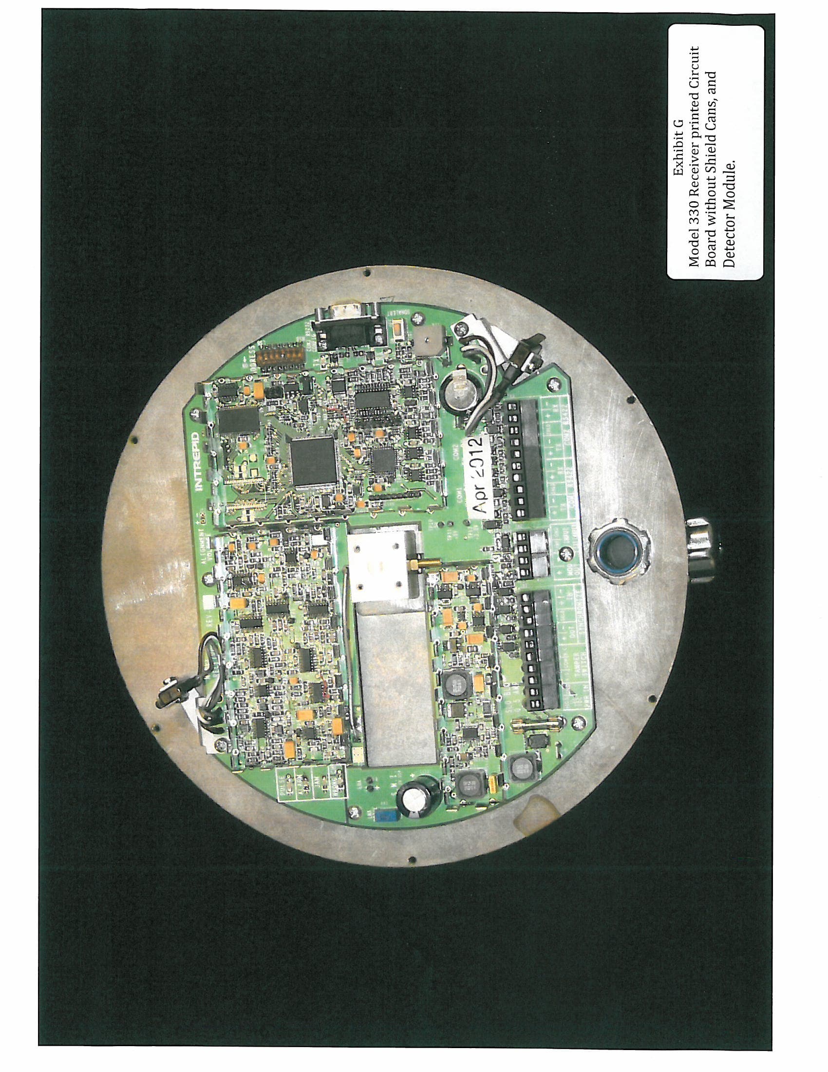
CA6330
Sep 12, 2012Digital Microwave Field Disturbance Sensor
Equipment Class
FDS - Part 15 Field Disturbance Sensor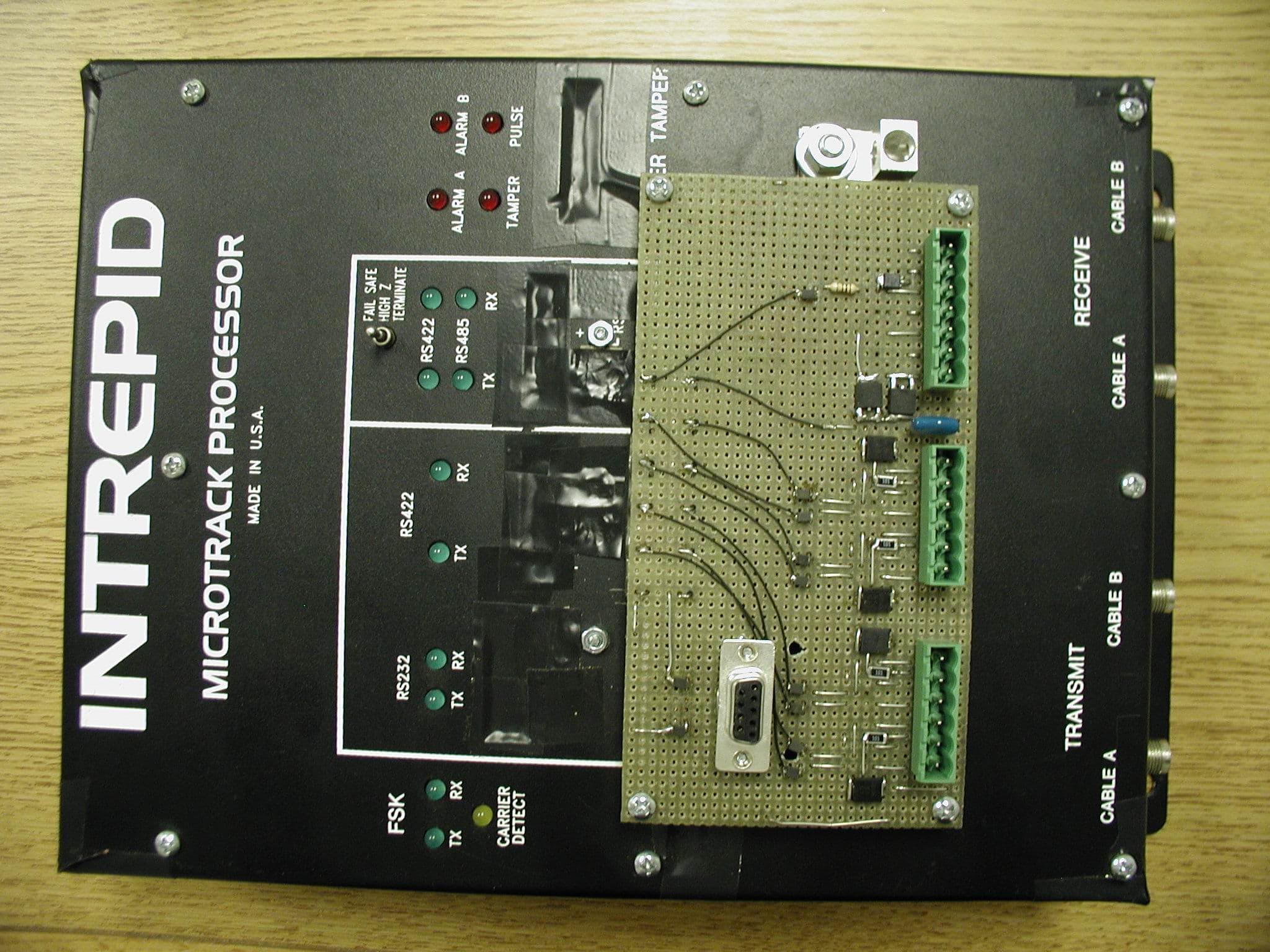
CA6MTP
Mar 06, 2011Perimeter Intrusion Sensor
Equipment Class
FDS - Part 15 Field Disturbance Sensor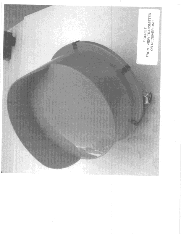
CA6316
Jan 02, 2000FDS - Part 15 Field Disturbance Sensor
Equipment Class
FDS - Part 15 Field Disturbance Sensor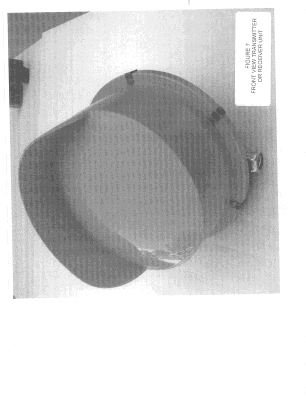
CA6315
Jan 02, 2000FDS - Part 15 Field Disturbance Sensor
Equipment Class
FDS - Part 15 Field Disturbance Sensor