CCRAH1NAirline 77 Wireless Microphone Transmitter
Sam Ash Music Corporation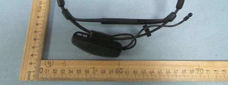
Click to zoom
Application Details
- Equipment Class
- TNT - Licensed Non-Broadcast Transmitter Worn on Body
- Date of Grant
- Sep 18, 2014
- Application Purpose
- Original Equipment
- Date of Application
- Sep 18, 2014
- Equipment Note
- Airline 77 Wireless Microphone Transmitter
- Frequency Range
- 642.37500000 - 645.75000000
- Company
- Sam Ash Music Corporation
- Country
- United States
Documents & Files
Document Text
Text extracted from the exhibit documents filed with the FCC. Open a document above to read the original.
Users Manual
U H F WIRELESS S Y STEM • AH1/ Transmitter • CR77 Receiver OWNE R S MANU A L AH1 T RANSMIT T E R ENGLISH Introduction 3 QuickStart 4 Guided Tour - CR77 Receiver 6 Guided Tour - AH1 Transmitter 9 Setting Up and Using Your AirLine System 11 47 Channel Plan 49 FRANCAIS Introduction 14 Prise en main 15 Visite guidée – Récepteur CR77 17 Visite guidée – Emetteur AH1 20 47 Tableau de conversion de fréquence 49 Copyright 2011, Samson Technologies Corp. V5 Samson Technologies Corp. 45 Gilpin Avenue Hauppauge, New York 11788-8816 Phone: 1-800-3-SAMSON (1-800-372-6766) Fax: 631-784-2201 www.samsontech.com Table of Contents DEUTSCHE Einleitung 25 Schneller Einstieg 26 Übersicht - Empfänger CR77 28 Übersicht - Sender AH1 31 Systeme 33 Technische Daten 47 Frequenzzuordnung der Empfangskanäle 49 ESPANOL Introducción 36 Arranque rápido 37 Recorrido guiado – Receptor CR77 39 Recorrido guiado – Transmisor AH1 42 Ajuste y uso de su sistema AirLine 44 47 Tabla de conversión de frecuencias 49 Con guration et utilisation des systèmes AirLine 22 Welcome to Samson AirLine—the wireless syst em for the new millenium! Wir eless microphone and instrument syst ems wer e orig inally developed to eliminate cables, providing unparalleled fr eedom of movement. AirLine takes this concept to a new level with tr ansmitters so small, lightweight and aerodynamic, they ar e nearly in visible, providing a completely “hassle-free” user experience. To cr eate the world ’s smallest wireless tr ansmitters, we developed new proprietary technology. Featuring miniaturiz ed circuitry and the ability to operate on a single tiny AAA batt ery (with 14 hours typical batt ery lif e), these tr ansmitters also feature signi cantly improved wireless reception and sound quality. Samson AirLine systems operate in the N, U and E bands UHF frequency range and contains a CR77 true diversity receiver (for professional performance applications) .The AirLine UHF System combines a feather-light AH1 headset transmitter with a Samson Q Series headset microphone, ideal for tness and performance applications. The AirLine UHF Wind Instrument System combines the AH1 with a Samson HM40 horn microphone. It is the rst wireless system designed for brass and reed instruments that eliminates the need for a body pack and unwieldy microphone cables that limit your movement. In this manual, you’ll nd a more detailed description of the features of all AirLine syst ems, as well as a guided tour through all components , st ep-by-step instructions for setting up your syst em and full speci cations. If your AirLine syst em was purchased in the United Sta tes, you’ll also nd a war ranty card enclosed—don’t forget to ll it out and mail it! This will enable you to receive online technical support and will allow us to send you updated information about this and other Samson products in the future. If your AirLine syst em was purchased out- side of the U. S., contact your local distributor for war ranty details. Also, be sure to check out our website (h ttp://www.samsontech.com) for complete inf ormation about our full product line. SPECIAL NOTE for U.S. purchasers: Should your AirLine syst em ever require servicing, a Return Authorization number (R A) is necessary. Without this number, the unit will not be accepted. If your AirLine syst em was purchased in the United Sta tes, please call Samson at 1-800- 372-6766 for a Return Authorization number prior to shipping your syst em. If possible, return the unit in its orig inal carton and packing mater ials. If your AirLine syst em was purchased outside of the U. S., contact your local distributor for information. If you’ve had some prior experience using wireless syst ems, these QuickStart instructions will get you up and running with your AirLine sys- Samson AirLine Intr oduction ENGLISH tem in a matter of minutes! Detailed instructions for setting up and using your AirLine system can be found on page 14 of this manual, and the “Guided Tour” sections on pages 4 - 13 provide full descriptions of all AirLine component controls and displays. 1. Make sure that the supplied receiver and AH1 transmitter are factory preset to the same channel. 2. Physically place the receiver where it will be used and extend its antenna(s) vertically. 3. Set the power switch on your UH1 transmitter to the “off” position (away from the arrow) and place a fresh battery in it. Then turn the transmitter back on momentarily; its LED will flash once and then go off if the battery is sufficiently strong. Once battery strength is verified, turn the transmitter off again. 4. If you are using an AH1 headset microphone, position it correctly as per the illustrations on page 12. If you are using an AirLine UHF Wind Instrument System, clamp the horn mic to your instrument as described in the supplied HM40 owners manual. 5. Turn your audio system off and make the physical cable connection between the receiver’s balanced or unbalanced output jack (if nec- essary, both can be used simultaneously) and a mic level audio input of your amplifier or mixer. If your system contains a CR77,be sure to set its Audio Output Level switch correctly. 6. Turn the Volume, Level or AF Level knob on the receiver completely counterclockwise. Connect the supplied AC adapter to the receiver and plug it in , but leave its power off for the moment. 7. Turn on the receiver. If your system contains a CR77 receiver, its “Power” LED will light steadily red. Samson AirLine QuickStart ENGLISH 8. Turn on your AH1 transmitter. If your system contains an AR1 receiver, its “Power/ RF” LED should change color from red to green, indicat- ing that it is receiving valid RF signal and is placed and positioned correctly. If your system contains either a CR77 one of the “A/B Receiver” LEDs will be lit, showing you whether the (left) “A” or (right) “B” receiver is currently being used. The CR77 meter will also indicate the strength of the incoming RF signal. 9. Turn on your connected amplifier and/or m…
Text truncated - open the document above for the full version.
Cover Letter(s)
Sam Ash Music Corporation Federal Communications Commission Authorization and Evaluation Division 1435 Oakland Mills Road Columbia, MD 21046 Date: 2014.09.05 SUBJECT: FCC Application for CCRAH1N To Whom It May Concern: I, the undersigned, hereby attest to the fact that I will apply the Declaration of Conformity procedure to the class B computer peripheral portion of this composite device. I understand the following FCC requirements: 1.Devices subject to the DoC procedure are required to be tested to show compliance with the FCC technical regulations by a recognized accredited testing laboratory. The testing laboratory must be accredited by a Commission approved accreditation body or designated under the terms of a government-to-government Mutual Recognition Agreement (MRA). A listing of those accredited testing laboratories that have been recognized by the Commission is published on the FCC Webpage: https://apps.fcc.gov/oetcf/eas/reports/TestFirmSearch.cfm (Select the "accredited" option to search for FCC recognized accredited test firms.) 2.Test facilities located in countries, where the U.S. does not have an operational Telcom MRA are not recognized by the FCC to test for the DoC procedure. 3.Pt 2.1077 contains the list of information that must be included in the Declaration of Conformity, which must be supplied with each product sold. The DoC complian ce info shall be included in the User’s Manual or as a separate sheet. The info must contain the name, address, and phone number of the responsible party, which must be located within the United States. According to 2.909(c)(2), the responsible party is either the Manufacturer or if the product is imported the Importer . Regards, Signature:(Must be signed by the person that is listed on the FCC Website) ................................................... Typed name and title: Don Albanese /Manager Applicant: Sam Ash Music Corporation Address: 262 Duffy Avenue Hicksville, NY 11801 United States
Cover Letter(s)
Names of parts Amount Reference GRM1882C1H470JA01D 15 C3,C6,C7,C9,C10,C11,C13,C14, C15,C60,C61,C62,C63,C64,C71 C1608CH1H121JT 1 C8 TEESVA1C106M8R 3 C16,C18,C19 GRM1882C1E102JA01D 2 C2,C17 TEESVA0G336M8R 7 C1,C20,C21,C22,C23,C24,C39 TMCMA1E105MTRF 2 C26,C27 TMCMA0J156MTRF 3 C25,C32,C40 C1608CH1H471JT 3 C34,C35,C36 C1608JB1E103KT 1 C37 C1608JF1C104ZT 1 C38 C1608CH1H030CT 1 C41 GRM1884C1H1R0BZ01D 1 C42 TEESVC1A107M12R 1 C45 TEESVB20J476M8R 2 C46,C58 C1608CH1H330JT 1 C48 C1608JB1C273KT 1 C49 C1608CH1H151JT 1 C50 C1608JB1H123KT 1 C51 C1608CH1H020CT 1 C52 C1608CH1H060DT 2 C44,C53 C1608CH1H070DT 1 C54 C1608CH1H040CT 2 C43,C55 TEESVP0J475M8R 1 C56 C1608JB1H222KT 3 C28,C29,C57 TMCMA1C475MTRF 4 C30,C31,C68,C70 TEESVB20G157M8R 1 C69 KV1837KTR-G 1 D1 1SS362-TE85L,F 1 D2 1SS349-TE85L,F 1 D3 LL1608-FSLR10J 2 L1,L9 LLQ1608-F15NG 1 L3 LL1608-FSL10NJ 2 L4,L8 LL1608-FSL15NJ 2 L5,L6 #A921CY-101M=P3 1 L7 TLSU1008A(T04) 1 LED1 15660-R PCB(AH1) 1 PCB1 FH102A-TR-E(FH102-TR-E) 1 Q2 2SC5231A-8/9-TL-E(2SC5231-C) 1 Q3 2SA1832(Y)-TE85L,F 1 Q4 2SK879(Y)-TE85R,F 1 Q5 RK73B1JTTD33Ω(J) 1 R1 RK73B1JTTD470Ω(J) 1 R2 RK73B1JTTD1KΩ(J) 5 R3,R16,R17,R34,R50 RK73B1JTTD18Ω(J) 1 R5 RK73B1JTTD24KΩ(J) 1 R7 RK73B1JTTD100KΩ(J) 3 R8,R24,R37 RK73B1JTTD6.8KΩ(J) 1 R9 RK73B1JTTD2KΩ(J) 1 R10 RK73B1JTTD330Ω(J) 1 R13 RK73B1JTTD4.7KΩ(J) 1 R15 RK73B1JTTD22KΩ(J) 2 R19,R20 RK73B1JTTD36KΩ(J) 1 R23 RK73B1JTTD10KΩ(J) 1 R26 RK73B1JTTD33KΩ(J) 2 R21,R27 RK73B1JTTD8.2KΩ(J)1 R28 RK73B1JTTD4.3KΩ(J)3 R29,R30,R40 RK73B1JTTD100Ω(J)5 R4,R6,R32,R33,R43 RK73B1JTTD51KΩ(J)1 R35 RK73B1JTTD68KΩ(J)1 R36 RK73B1JTTD5.1KΩ(J)1 R39 RK73B1JTTD56KΩ(J)1 R41 RK73B1JTTD15Ω(J)1 R42 RK73B1JTTD3.3KΩ(J)2 R22,R44 RK73B1JTTD680Ω(J)2 R31,R49 RK73B1JTTD2.2KΩ(J)2 R12,R51 SLHA12BP-042 SW1,SW2 #395-01001 T1 TK10690MTL-A 1 U1 TK11227CMCL-A 1 U2 XC6371A300 1 U3 TK17030M 1 U4 XC61CN11 1 U5 PVA2A473A01R001 VR2 PVA2A103A01R001 VR3 3314J-1-502E-LF1 VR4 NS-32R 642.375M 1 X1 NS-32R 642.875M 1 X1 NS-32R 644.125M 1 X1 NS-32R 644.750M 1 X1 NS-32R 645.500M 1 X1 NS-32R 645.750M 1 X1 AH1 PCBASSY(RoHS)1
External Photos
Waltek Services (Shenzhen) Co.,Ltd. http://www.waltek.com.cn Photographs – Const ructional Details Model AH1 – Appearance View Waltek Services (Shenzhen) Co.,Ltd. http://www.waltek.com.cn Waltek Services (Shenzhen) Co.,Ltd. http://www.waltek.com.cn
ID Label/Location Info
FCC Label Location for model: AH1 The Label must not be a stick-on paper. The Label on these products must be permanently affixed to the product and readily visible at the time of purchase and must last the expected lifetime of the equipment not be readily detachable.
ID Label/Location Info
FCC Label Sample for model: AH1 Model: AH1 FCC ID: CCRAH1N
Internal Photos
Waltek Services (Shenzhen) Co.,Ltd. http://www.waltek.com.cn ANT. Waltek Services (Shenzhen) Co.,Ltd. http://www.waltek.com.cn
Parts List/Tune Up Info
Tune up Procedure Model: AH1 Modulation: FM 642.375 MHz ~ 645.750 MHz: Channel Max output power Frequency tolerance 642.375MHz 5±2dBm ±10KHz 645.750 MHz 5±2dBm ±10KHz
RF Exposure Info
RF Exposure Date: Sep. 18,2014 FCC ID: CCRAH1N KDB 447498 D01 v05r02, Section 4.3.1 1) The 1‐g and 10‐g SAR test exclusion thresholds for 100 MHz to 6 GHz at test separation distances ≤ 50 mm are determined by: [(max. power of channel, including tune‐up tolerance, mW)/(min. test separation distance, mm)] · [√f(GHz)] ≤ 3.0 for 1‐g SAR and ≤ 7.5 for 10 ‐g extremity SAR,25 where • f(GHz) is the RF channel transmit frequency in GHz • Power and distance are rounded to the nearest mW and mm before calculation26 • The result is rounded to one decimal place for comparison • 3.0 and 7.5 are referred to as the numeric thresholds in the step 2 below The test exclusions are applicable only when the minimum test separation distance is ≤ 50 mm and for transmission frequencies between 100 MHz and 6 GHz. When the minimum test separation distance is < 5 mm, a distance of 5 mm according to 5) in section 4.1 is applied to determine SAR test exclusion. This device is operated at 642.375~645.750MHz, the max. power measured is 3.75 mW and test separation distance is less than 5mm. Step 1) [(max. power of channel, including tune‐up tolerance, mW)/(min. test separation distance, mm)] · [√f(GHz)] ≤ 3.0 (3.75 mW/5mm)*√ (0.645GHz)= 0.6≤ 3.0 Result: PASS.
Test Report
Waltek Services (Shenzhen) Co.,Ltd. http://www.waltek.com.cn Page 1 of 30 TEST REPORT Reference No. .................... : WTS14S0917955E FCC ID ................................ : CCRAH1N Applicant ............................ : Sam Ash Music Corporation Address .............................. : 262 Duffy Avenue Hicksville, NY 11801 United States Manufacturer .................... : The same as above Address .............................. : The same as above Product Name .................... : Airline 77 Wireless Microphone Transmitter Model No. ........................... : AH1 Standards ........................... : FCC CFR47 Part 74 Date of Receipt sample ..... : Aug. 30, 2014 Date of Test ........................ : Sep.01~10, 2014 Date of Issue ...................... : Sep. 10, 2014 Test Result ......................... : Pass Remarks: The results shown in this test report refer only to the sample(s) tested, this test report cannot be reproduced, except in full, without prior written permission of the company.The report would be invalid without specific stamp of test institute and the signatures of compiler and approver. Prepared By: Waltek Services (Shenzhen) Co., Ltd. Address: 1/F., Fukangtai Building, West Baima Road, Songgang Street, Baoan District, Shenzhen, Guangdong, China Testing location: 1/F., Fukangtai Building, West Baima Road, Songgang Street, Baoan District, Shenzhen, Guangdong, China Tel :+86-755-83551033 Fax:+86-755-83552400 Compiled by: Approved by: Zero Zhou / Project Engineer Philo Zhong / Manager Reference No.: WTS14S0917955E Page 2 of 30 Waltek Services (Shenzhen) Co.,Ltd. http://www.waltek.com.cn 2 Test Summary Test Items Test Requirement Test Method Result RF Output Power 74.861(e)(1)(ii) TIA/EIA-603-C-2004 PASS Modulation Characteristics 2.1047(a) TIA/EIA-603-C-2004 PASS Occupied Bandwidth 2.1049(c)(1) TIA/EIA-603-C-2004 PASS Radiated Emissions 2.1053 & 74.861(e)(6) TIA/EIA-603-C-2004 PASS Spurious emissions at antenna terminals 2.1051 TIA/EIA-603-C-2004 PASS Frequencies Stability 2.1055(a)(1) TIA/EIA-603-C-2004 PASS Remark: PASS means that the test results complies with related requirements. N/A means that the test is not applicable for the EUT. Reference No.: WTS14S0917955E Page 3 of 30 Waltek Services (Shenzhen) Co.,Ltd. http://www.waltek.com.cn 3 Contents Page 1 COVER PAGE ........................................................................................................................................................ 1 2 TEST SUMMARY ................................................................................................................................................... 2 3 CONTENTS ............................................................................................................................................................. 3 4 GENERAL INFORMATION .................................................................................................................................. 5 4.1 GENERAL DESCRIPTION OF E.U.T. ................................................................................................................. 5 4.2 DETAILS OF E.U.T. .......................................................................................................................................... 5 4.3 CHANNEL LIST ................................................................................................................................................. 5 4.4 TEST MODE ..................................................................................................................................................... 5 4.5 TEST FACILITY ................................................................................................................................................. 5 4.6 TEST LOCATION ............................................................................................................................................... 5 5 EQUIPMENT USED DURING TEST ................................................................................................................... 6 5.1 EQUIPMENTS LIST ........................................................................................................................................... 6 5.2 MEASUREMENT UNCERTAINTY ........................................................................................................................ 6 5.3 TEST EQUIPMENT CALIBRATION ...................................................................................................................... 6 6 RF OUTPUT POWER ............................................................................................................................................ 7 6.1 TEST PROCEDURE ........................................................................................................................................... 7 6.2 TEST RESULT ................................................................................................................................................... 7 7 MODULATION CHARACTERISTICS ................................................................................................................ 9 7.1 TEST PROCEDURE ............................................................................................................................................. 9 7.2 TEST RESULT ................................................................................................................................................ 10 8 OCCUPIED BANDWIDTH OF EMISSION ....................................................................................................... 12 8.1 TEST PROCEDURE ......................................................................................................................................... 12 8.2 TEST RESULT ................................................................................................................................................ 12 9…
Text truncated - open the document above for the full version.
Test Setup Photos
Waltek Services (Shenzhen) Co.,Ltd. http://www.waltek.com.cn Photographs –Model AH1 Test Setup Photograph – Radiation Spurious Emission Test Setup 30MHz-1GHz Above 1GHz
Contact Information
Applicant
Don Albanese
Test Firm
Waltek Services(Shenzhen) Co., Ltd.Philo zhong
Technical Specifications
| # | Rule Parts | Frequency Range | Power Output | Emission | Tolerance |
|---|---|---|---|---|---|
| 1 | 74 | 642.375 MHz - 645.75 MHz | 3.75 mW | 45K9F8E | 0.0015000000 % |
Other Applications from Sam Ash Music Corporation
CCRCBXD2
Jan 11, 2024TRANSMITTER
Equipment Class
PUT - Part 15 Unlicensed PCS portable Tx worn on body
CCRCHXD2
Jan 11, 2024TRANSMITTER
Equipment Class
PUF - Part 15 Unlicensed PCS portable Tx held to face
CCRET100
Jan 09, 2024ET100 UHF Transmitter
Equipment Class
TLD - Licensed LPAS Device
CCRXP106W
May 20, 2020Bluetooth Speaker
Equipment Class
DSS - Part 15 Spread Spectrum Transmitter
CCRRXD1M
Mar 18, 20202.4G Wireless microphone Receiver
Equipment Class
DXX - Part 15 Low Power Communication Device Transmitter