CCRAX1Airline UHF Wireless System
Sam Ash Music Corporation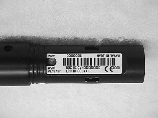
Click to zoom
Application Details
- Equipment Class
- TNF - Licensed Non-Broadcast Transmitter Held to Face
- Date of Grant
- Jul 04, 2000
- Application Purpose
- Original Equipment
- Date of Application
- Jun 05, 2000
- Equipment Note
- Airline UHF Wireless System
- Frequency Range
- 801.37500000 - 804.75000000
- Company
- Sam Ash Music Corporation
- Country
- United States
Documents & Files
Document Text
Text extracted from the exhibit documents filed with the FCC. Open a document above to read the original.
Users Manual
® UHF Wireless System Owners Manual Headset Transmitter Handheld Transmitter Presentation Transmitter • AX1 Handheld Transmitter • AL1 Presentation Transmitter • AH1/QE Aerobics Headset Transmitter • AH1/QV Vocal Headset Transmitter • AH1/35X Wind Instrument Transmitter • AR1 Receiver Wind Instrument Transmitter ENGLISH Introduction 1 QuickStart 2 Guided Tour - AR1 Receiver 4 Guided Tour - AX1 Handheld Transmitter 6 Guided Tour - AL1 Body Pack Transmitter 8 Guided Tour - AH1 Headset Transmitter 11 Setting Up and Using Your AirLine System 14 Appendix A: AirLine Wind Instrument System 69 Specifications 73 Channel Plan 75 FRANCAIS Introduction 18 Prise en main 19 Visite guidée – Récepteur AR1 21 Visite guidée – Emetteur main AX1 23 Visite guidée – Emetteur de ceinture AL1 25 Visite guidée – Emetteur serre-tête AH1 28 Configuration et utilisation des systèmes AirLine 31 Annexe A : Système AirLine Wind Instrument 70 Spécifications 73 Tableau de conversion de fréquence 75 Samson Technologies Corp. 575 Underhill Blvd. P.O. Box 9031 Syosset, NY 11791-9031 Phone: 1-800-3-SAMSON (1-800-372-6766) Fax: 516-364-3888 Table of Contents Produced by On The Right Wavelengthfor Samson Technologies Corp. Copyright 2000, Samson Technologies Corp. Printed March 2000 DEUTSCHE Einleitung 35 Schneller Einstieg 36 Übersicht - Empfänger AR1 38 Übersicht - Hand-Sender AX1 40 Übersicht - Gürtel-Sender AL1 42 Übersicht - Kopfbügel-Sender AH1 45 Konfiguration und Betrieb der AirLine-Systeme 48 Anhang A: „AirLine Wind Instrument“-System 71 Technische Daten 73 Frequenzzuordnung der Empfangskanäle 75 ESPANOL Introducción 52 Arranque rápido 53 Recorrido guiado – Receptor AR1 55 Recorrido guiado – Transmisor manual AX1 57 Recorrido guiado – Transmisor de petaca AL1 59 Recorrido guiado – Transmisor de diadema AH1 62 Ajuste y uso de su sistema AirLine 65 Apéndice A: Sistema para instrumentos de viento AirLine 72 Especificaciones 73 Tabla de conversión de frecuencias 75 Welcome to Samson AirLine—the wireless system for the new millenium! Wireless microphone and instrument systems were originally developed to eliminate cables, providing unparalleled freedom of movement. AirLine takes this concept to a new level with transmitters so small, lightweight and aerodynamic, they are nearly invisible, providing a completely “hassle-free” user experience. To create the world’s smallest wireless transmitters, we developed new proprietary technology. Featuring miniaturized circuitry and the ability to operate on a single tiny AAA battery (with 14 hours typical battery life), these transmitters also feature significantly improved wireless reception and sound quality. What’s more, the AR1 micro receiver developed for the AirLine systems is actually smaller than the typical wireless transmitter. There are five different Samson AirLine systems detailed in this manual. All operate in the 801 - 805 MHz UHF frequency range and all contain either an AR1 micro receiver or a UR1 true diversity receiver (from our acclaimed Series One system). The AirLine UHF Microphone System contains an AX1 hand-held transmitter, which plugs into any standard wired dynamic microphone. The AirLine UHF Presentation System contains an AL1 transmitter, which contains a built-in electret condenser microphone and connection for an optional lavalier microphone. The AirLine UHF Performance System combines a feather-light AH1 headset transmitter with a Samson QV headset microphone, while the AirLine UHF Fitness System combines the AH1 with a Samson QE headset microphone. Finally, the AirLine UHF Wind Instrument System combines the AH1 with an Audio-Technica Pro 35X horn microphone. In this manual, you’ll find a more detailed description of the features of all AirLine systems, as well as a guided tour through all components, step-by-step instructions for setting up your system and full specifications. If your AirLine system was purchased in the United States, you’ll also find a warranty card enclosed—don’t forget to fill it out and mail it! This will enable you to receive online technical support and will allow us to send you updated information about this and other Samson products in the future. If your AirLine system was purchased outside of the U. S., contact your local distributor for warranty details. Also, be sure to check out our website (http://www.samsontech.com) for complete information about our full product line. SPECIAL NOTE for U.S. purchasers: Should your AirLine system ever require servicing, a Return Authorizationnumber (RA) is necessary. Without this number, the unit will not be accepted. If your AirLine system was purchased in the United States, please call Samson at 1-800-372-6766 for a Return Authorization number prior to shipping your system. If possible, return the unit in its original carton and packing materials. If your AirLine system was purchased outside of the U. S., contact your local distributor for information. 1 Samson AirLine Introduction ENGLISH If you’ve had some prior experience using wireless systems, these QuickStart instructions will get you up and running with your AirLine system in a matter of minutes! Detailed instructions for setting up and using your AirLine system can be found on page 14 of this manual, and the “Guided Tour” sections on pages 4 - 13 provide full descriptions of all AirLine component controls and displays. 1. Make sure that the supplied AR1 receiver and AX1, AL1 or AH1 transmitter are factory preset to the same channel. 2. Physically place the AR1 where it will be used (if desired, it can be wall-mounted using the supplied holder) and extend its antenna vertically. 3. Set the power switch to your transmitter to the “off” position (away from the arrow) and place a fresh battery in it. Then turn the transmitter back on momentarily; its LED will flash once and then go off if the battery is sufficiently strong. Once battery strength is verified, turn the transmitter off. 4. If you are using an AX1, plug its XLR conne…
Text truncated - open the document above for the full version.
Operational Description
AX1 CIRCUIT FUNCTIONPOWER SUPPLY UNITD3 1SS349 diode DC-DC U3 XC6371A300 IC(DC-DC) DC-DC U2 TK11227 IC (regulator) power supply regulator(2.7V) U5 XC61CN11 IC(detect) LED driver LED1 TLSU1008 LED power supply indicator(LOW) & unavailable indicator AUDIO UNITD2 1SS362 diode modulation AF signal level limit Q5 2SK879 transistor AF mute Q4 2SA1832 transistor AF mute drive U1 TK10690 IC(compander) 1/2 log compander U4 TK17030 IC(opeamp) pre-emphasis RF UNITD1 KV1832E diode frequency adjustment & modulat Q2 FH102 transistor OSC & buffer Q3 2SC5231 transistor output power amplifier VOLTAGE AND CURRENT OF FINAL STAGEcollector voltage Vc=2.7V emitter voltage Ve=0.38V current Ic=3.8mA A_1 Components Function Page 1
Operational Description
AX1 Expla 1 2 3 4 ataion of Spurious Limitation Not use lower frequency than the transmission frequency 800MHz - Direct Oscillation. Emitter coupling which has less spurious is used for between oscillation stage and buffer. Ouput side of the final stage is tuning type which has proper matching. It limits higher harmonic factor. Low pass filter located at the final stage eliminates higher harmonic factor. Utilizing SAW Resonator. VCO etc. process. Pai type 2 stages.
Parts List/Tune Up Info
93181 1SS349-TE85L1D3 139181 1SS362-TE85L1D2 157891 2SA1832(Y)-TE85L1Q4 1472825 2SC5231-C8/C9-TL1Q3 116891 2SK879(Y)-TE85R1Q5 1579366 3314J-1-5021VR4 1468025 395-01001T1 1580225 A921CY-101M P31L7 1120521 C1608CH1H020CT-A1C43 1120621 C1608CH1H030CT-A3C41,C42,C52 1120721 C1608CH1H050CT-A3C44,C54,C55 1120921 C1608CH1H070DT-A1C53 1039921 C1608CH1H161JT-A1C50 1121621 C1608CH1H330JT-A1C48 939321 C1608CH1H471JT-A3C34,C35,C36 1398121 C1608JB1C273KT-N1C49 1122221 C1608JB1E103KT-A1C37 1435521 C1608JB1H123KT-N1C51 1373521 C1608JB1H222KT-A3C28,C29,C57 1123921 C1608JF1C104ZT-A2C38,C56 25 FS-3351X1 1254726 GRM39CH102J25PT2C2,C17 C3,C4,C6,C7,C8,C9,C10,C11,C13, C14,C15,C61,C62,C63,C64,C71, C72,C73 1580525 KV1832ETR1D1 1373625 LL1608-FH10NJ2L3,L4 1395225 LL1608-FH12NJ1L6 1388025 LL1608-FH8N2J2L5,L8 1389525 LL1608-FHR10J2L1,L9 1581226 POZ2AN-1-103N-T001VR3 1564626 POZ2AN-1-503N-T001VR2 112021 RK73K1JTD100KJ3R8,R24,R37 116251 RK73K1JTD100Ohms6R4,R5,R6,R32,R33,R43 111921 RK73K1JTD10KJ2R10,R26 151621 RK73K1JTD15Ohms1R42 111841 RK73K1JTD1KJ4R3,R16,R17,R34 111851 RK73K1JTD2.2KJ1R12 114891 RK73K1JTD22KJ2R19,R20 136881 RK73K1JTD24KJ1R7 111871 RK73K1JTD3.3KJ3R22,R44,R49 111831 RK73K1JTD330Ohms1R13 111961 RK73K1JTD33KJ1R21 116231 RK73K1JTD33Ohms1R1 111971 RK73K1JTD36KJ1R23 116651 RK73K1JTD4.3KJ3R29,R30,R40 111881 RK73K1JTD4.7KJ1R15 112961 RK73K1JTD470Ohms1R2 111981 RK73K1JTD47KJ1R27 111891 RK73K1JTD5.1KJ1R39 111991 RK73K1JTD51KJ1R35 114881 RK73K1JTD56KJ1R41 111911 RK73K1JTD6.8KJ1R9 116661 RK73K1JTD680Ohms1R31 120841 RK73K1JTD68KJ1R36 116971 RK73K1JTD8.2KJ1R28 1467321 SK2-0J475M-RA2C30,C31 1467721 SK2-1E105M-RA4C26,C27,C68,C70 1467421 SK4-0J106M-RA3C16,C18,C19 1581021 SK4-1A107M-RD1C45 1581121 SK5-0G476M-RB2C46,C58 1467221 SK5-0J156M-RA3C25,C32,C40 1579121 SK6-0G336M-RA7C1,C20,C22,C23,C24,C39,C69 1579264 SLHA12BP-041SW1 1386725 TK10690MTL1U1 1580825 TK11227BMCL1U2 1580325 TK17030MTL1U4 157881 TLSU1008(T04)1LED1 1580669 XC61CN1102NR1U5 1580769 XC6371A300PR1U3 AX1 PARTS 1536926 GRM39CH470J50PT18
Parts List/Tune Up Info
No Item Details Adjustment Point Settings/Standards Notes 1 Initial Setting Set PCB and initial setting PCB power switch = ON 2 Power supply input Supply power at battery terminal. 1.5V 3 Consumption Current Confirmation Consumption current at 1.5V. Less than 70mA 4 Internal Voltage Confirmation Ouput voltage of DC-DC Converter. 3.0V 5 Frequency Adjustment Adjust each channel to the specified frequency. VR2 by spectum analyzer. Specified frequency +/-5kHz. 6 RF Output Level Confirmation Check by spectrum analyzer. +3dBm - +10dBm 7 Spurious Level Confirmation Check by spectrum analyzer. Less than 1uW. 8 User Volume Setting Set to 11 o'clock position. VR4 9 Deviation Adjustment Adjust by audio output from receiver. VR3/Audio analyzer Receiver output 0dBv +/- 1dB Audio generator -20dBv 10 Distortion Ratio Confirmation Adjust by audio output from receiver. Less than 2% Audio generator -30dBv 11 Frequency Response Confirmation Adjust by audio output from receiver. +/-3.5dB over 50Hz to 15kHz (ref. 1kHz) Audio generator -4 0dBv 12 Power Switch Operation Confirmation 1 Measure consumption current at power switch OFF. 0mA 13 Power Switch Operation Confirmation 2 Confirm LED 1 flash when power switch ON. Tip of optical fiber jig 14 Low Voltage Indication Confirmation 1 Lights off LED 1. Tip of optical fiber jig Power supply voltage 1.15V. 15 Low Voltage Indication Confirmation 2 Lights LED 1. Tip of optical fiber jig Power supply voltage 1.05V. 16 Low Voltage Operation Confirmation Check at DC-DC convertor output voltage. Power supply voltage 0.9V. within 3.0V +/- 0.1V AX1 PCB Adjustment & Confirmation Method
Test Report
Applicant: Samson Technologies FCC ID: CCRAX1 Retlif Testing Laboratories Report No.: R-8512-2 GENERAL INFORMATION REQUIREMENTS Paragraph 2.983(a) Name of Applicant:Samson Technologies Address of Applicant:575 Underhill Blvd. Syosset, NY 11791 Name of Manufacturer:Samson Technologies Paragraph 2.983(b) Equipment Identification:FCC ID: CCRAX1 Paragraph 2.02(c)(1) Necessary Bandwidth Determination: The necessary bandwidth was calculated utilizing the following formula: B n = 2M + 2DM = 32.8 kHz D = 15 kHz B n = 2(32.8) + 2(15) = 95.6 kHz Applicant: Samson Technologies FCC ID: CCRAX1 Retlif Testing Laboratories Report No.: R-8512-2 Paragraph 2.1046 Power Output, Effective Radiated Power Applicant: Samson Technologies FCC ID: CCRAX1 Retlif Testing Laboratories Report No.: R-8512-2 POWER OUTPUT, EFFECTIVE RADIATED POWER (Para. 2.1046) A. Measurement Procedure: The transmitter under test was placed on an 80 cm. high non metallic table on the Open Air Test Site with its antenna polarized vertically. A receive dipole antenna was placed three meters away from the transmitter. The turntable was rotated 360 degrees and the receive antenna was raised and lowered from 1 to 4 meters until a maximum reading was obtained. This reading was recorded. The transmitter under test was replaced with a dipole and signal generator. The signal generator was set to the frequency of the transmitter under test. The level of the signal generator was increased until the level was equal to that previously measured. The required input level from the signal generator in dBm was recorded and converted into milliwatts. This was the Effective Radiated Power of the transmitter. Setup of the test is shown below: B.Test Results: The results for the above test are submitted as a separate attachment named ERP.pdf. Pre Amp lif ier Spectrum Analyzer Broadband Antenna 3 M 4M Tes t Sa mp le Applicant: Samson Technologies FCC ID: CCRAX1 Retlif Testing Laboratories Report No.: R-8512-2 Paragraph 2.1047 Modulation Characteristics Applicant: Samson Technologies FCC ID: CCRAX1 Retlif Testing Laboratories Report No.: R-8512-2 MODULATION CHARACTERISTICS (2.1047) A. Measurement Procedure: An Audio Oscillator was directly coupled to the audio input of the transmitter under test. The RF Output at the antenna terminals was loosely coupled to a modulation meter as shown below. The audio level applied to the input was adjusted from –50dBm to +10dBm at each frequency listed herein. At each test frequency and level, the FM modulation was recorded. Setup of the above test is shown below: B. Test Results: The test data for this method are being submitted as a separate attachment, named modchar.pdf. EXTERNAL ATTENUATOR MODULATION METER AUDIO OSCILLATOR EUT AUDIO Applicant: Samson Technologies FCC ID: CCRAX1 Retlif Testing Laboratories Report No.: R-8512-2 Paragraph 2.1049 Occupied Bandwidth Applicant: Samson Technologies FCC ID: CCRAX1 Retlif Testing Laboratories Report No.: R-8512-2 OCCUPIED BANDWIDTH (PARA.2.1049) A.Measurement Procedure: An audio signal was directly coupled to the audio input of the test sample. The RF output was monitored using a deviation meter. The audio input level was increased to produce a 50% deviation +16dB. The RF output was then loosely coupled through external attenuators to a spectrum analyzer. The occupied bandwidth of the RF carrier, modulated at 50% deviation +16dB, was then measured. The above procedure was performed with the audio input frequencies of 1000, 2500, and 15000 Hz. The modulated signal must be within the template as specified by the applicable paragraph in Part 74. Setup of the test is shown below: B.Test Results: The results for the above test are submitted as a separate attachment named occbw.pdf. Applicant: Samson Technologies FCC ID: CCRAX1 Retlif Testing Laboratories Report No.: R-8512-2 Para. 2.1053 Field Strength of Spurious Radiation Applicant: Samson Technologies FCC ID: CCRAX1 Retlif Testing Laboratories Report No.: R-8512-2 FIELD STRENGTH OF SPURIOUS RADIATION (PARA 2.1053) A.Measurement Procedure: The test sample was then placed on an 80cm high wooden test stand, which was located three meters from the test antenna on an FCC listed test site. The frequency range scanned was from the lowest frequency generated by the test sample to its tenth harmonic. In order to maximize the level of each emission observed from the test sample, the broadband antenna was tuned to the frequency of each emission and the test sample was rotated 360 degrees. To further maximize the each emission observed, the test antenna was both horizontally and vertically polarized, and then was raised and lowered from one to four meters from the ground plane. The limits for all of the spurious emissions was calculated utilizing the measured output power and the following equation: Limit <dB:V/M> = 20 log [{(49.2 x P T ) ½ /3} x 10 6 ] - (43 + 10 log P T ) The above procedure was performed at the lower, middle and upper frequencies of the device’s range. Setup of the test is shown below: B.Test Results: The results for the above test are submitted as a separate attachment named spurious case.pdf. Pre Amplifier Spectrum Analyzer Broadband Antenna 3 M 4 M Tes t Sa mp le Applicant: Samson Technologies FCC ID: CCRAX1 Retlif Testing Laboratories Report No.: R-8512-2 Paragraph 2.1055 Frequency Stability Applicant: Samson Technologies FCC ID: CCRAX1 Retlif Testing Laboratories Report No.: R-8512-2 FREQUENCY STABILITY MEASUREMENTS A.Measurement Procedure (Frequency vs. Voltage): The RF output of the test sample was coupled to a frequency counter through external attenuation. Using a Variable power supply and voltmeter, the input voltage was varied. Measurements were taken with the device being supplied with 85, 100, and 115 percent of its rated input voltage and set to transmit the unmodulated carrier frequency. Setup of the test is shown below: B.Test Results: The results for the above test are submitted as a separate attachment nam…
Text truncated - open the document above for the full version.
Test Report
TABULAR DATA SHEET CUSTOMER: MODEL No.: TEST SAMPLE: SERIAL No.: TEST SPECIFICATION: TEST METHOD: OPERATING MODE: TECHNICIAN:DATE: RETLIF TESTING LABORATORIES NOTES: DATA SHEETOF JOB No.: PARAGRAPH: 800MHz Wireless Transmitter FCC ID:CCRAX1 R-8512-2 The EUT was placed on a tabletop, and the radiated output level was measured with a dipole antenna. After the level was maximized, the EUT was replaced with another dipole and a signal generator. The level of the generator was raised until it matched the level recorded from the EUT and this was considered to be the output power. 1.41.571.51.3U4 250 | | | V 250 803.7 mWattsmWattsdBmdBuVMHz CONVERTED READING Signal Gen. Output Level METER READINGLIMITAntenna Orientation CHANNELCENTER FREQUENCY CONTINUOUSLY TRANSMITTING A CW SIGNAL AT CENTER FREQUENCY/CHANNEL SHOWN BELOW. 2.1046 FCC PART 2 Peter LanannaMay 4, 2000 POWER OUTPUT, EFFECTIVE RADIATED POWER METHOD, PARAGRAPH 2.1046 R-8512-2Samson Technologies AX1N/A 11
Test Report
TABULAR DATA SHEET CUSTOMER: MODEL No.: TEST SAMPLE: SERIAL No.: TEST SPECIFICATION: TEST METHOD: OPERATING MODE: TECHNICIAN:DATE: RETLIF TESTING LABORATORIES NOTES: DATA SHEETOF JOB No.: PARAGRAPH: Tolerance: +/- 0.005% (+/- .040188 MHz) UHF Wireless Transmitter R-8512-2 The test sample performed within the limits specified by the above listed specification. 803.71 | | | | | | | V 803.71 803.7211 803.7394 803.7563 803.7679 803.7741 803.7736 803.7737 803.7673 803.7546 803.7362 803.79 | | | | | | | V 803.79 -30 -20 -10 0 10 20 room temp 30 40 50 803.7737 | | | | | | | V 803.7737 803.75 | | | | | | | V 803.75 Pass Pass Pass Pass Pass Pass Pass Pass Pass Pass 04 | | | | | | | V 04 MHzMHzMHzDegrees C.MHzMHz Upper LimitMeter ReadingTemperaturePass / FailLower LimitAct. Transmit Frequency Channel Frequency Channel Transmitting on channel U4 (803.75 MHz) 74.861 (e) (4)Services, Subpart H; Low Power Auxiliary Stations. FCC Part 74, Subpart H;Experimental Radio, Auxiliary Special Broadcast, & other Program Distributional N. DragottaApril 27, 2000 Frequency Stability ( -30°C to +50°C ) R-8512-2Samson Technologies AX1N/A FCC ID: CCRAX1 22
Test Report
TABULAR DATA SHEET CUSTOMER: MODEL No.: TEST SAMPLE: SERIAL No.: TEST SPECIFICATION: TEST METHOD: OPERATING MODE: TECHNICIAN:DATE: RETLIF TESTING LABORATORIES NOTES: DATA SHEETOF JOB No.: PARAGRAPH: Tolerance: +/- 0.005% (+/- .040188 MHz) Temperature: 23° C. Humidity: 29% UHF Wireless Transmitter R-8512-2 The test sample performed within the limits specified by the above listed specification. ** = At this input voltage, the low battery LED on the unit illuminated. 803.71 803.71 803.71 803.71 803.7735 803.7737 803.7737 803.7735 803.79 803.79 803.79 803.79 1.28 1.50 1.73 **1.15 85 100 115 Battery End Point 803.75 803.75 803.75 803.75 Pass Pass Pass Pass 04 04 04 04 MHzMHzMHzVDC%MHz UPPER LIMITMETER READINGINPUT VOLTAGEPass / FailLOWER LIMITINPUT VOLTAGETRANSMIT FREQUENCY Channel Transmitting on channel U4 (803.75 MHz) 74.861 (e) (4)Services, Subpart H; Low Power Auxiliary Stations. FCC Part 74, Subpart H;Experimental Radio, Auxiliary Special Broadcast, & other Program Distributional N. DragottaApril 27, 2000 Frequency Stability (DC Input Power 85% TO 115% ) R-8512-2Samson Technologies AX1N/A FCC ID: CCRAX1 21
Test Report
TABULAR DATA SHEET CUSTOMER: MODEL No.: TEST SAMPLE: SERIAL No.: TEST SPECIFICATION: TEST METHOD: OPERATING MODE: TECHNICIAN:DATE: RETLIF TESTING LABORATORIES NOTES: DATA SHEETOF JOB No.: PARAGRAPH: **Modulation signal direct input of a 1 kHz signal at a level of -10 dBm. **Maximum Allowable Audio Frequency Response = 75 kHz Temperature: 23° C. Humidity:39% UHF Wireless Transmitter R-8512-2 0.100 0.300 0.500 1.000 1.500 2.000 2.500 5.000 10.000 15.000 20.000 -10 -10 -10 -10 -10 -10 -10 -10 -10 -10 -10 20.3 20.0 26.5 29.0 29.4 29.4 29.4 29.3 30.9 16.9 12.9 kHzdBkHz FM DeviationInput LevelAudio Input Frequency Transmitting on channel U4 (803.75 MHz) 74.861(e)(3)Services, Subpart H; Low Power Auxiliary Stations. FCC Part 74, Subpart H;Experimental Radio, Auxiliary Special Broadcast, & other Program Distributional N. DragottaMay 5, 2000 Audio Frequency Response ( 100 Hz TO 20 KHz ) R-8512-2Samson Technologies AX1N/A FCC ID: CCRAX1 11 TABULAR DATA SHEET CUSTOMER: MODEL No.: TEST SAMPLE: SERIAL No.: TEST SPECIFICATION: TEST METHOD: OPERATING MODE: TECHNICIAN:DATE: RETLIF TESTING LABORATORIES NOTES: DATA SHEETOF JOB No.: PARAGRAPH: Temperature: 23° C. Humidity: 39% UHF Wireless Transmitter R-8512-2 The test sample performed within the limits specified by the above listed specification. 13.7 21.4 26.6 29.1 29.4 29.7 29.7 12.4 20.4 23.0 28.8 29.4 29.6 29.8 11.4 19.1 21.9 28.1 29.0 29.5 29.8 10.6 18.0 21.7 21.0 26.5 28.8 29.6 10.2 17.3 21.7 20.5 20.0 23.8 22.7 9.6 16.4 22.0 21.5 20.3 20.3 21.6 75.0 75.0 75.0 75.0 75.0 75.0 75.0 -50 -40 -30 -20 -10 0 +10 kHzkHzkHzkHzkHzkHzkHzdbm Deviation @ 2 kHz AF Deviation @ 500 Hz AF Deviation @ 1 kHz AF MAXIMUM DEVIATION Deviation @ 1.5 kHz AF Deviation @ 300 Hz AF Deviation @ 100 Hz AF INPUT LEVEL Transmitting on channel U4 (803.75 MHz) 74.861(e)(3)Services, Subpart H; Low Power Auxiliary Stations. FCC Part 74, Subpart H;Experimental Radio, Auxiliary Special Broadcast, & other Program Distributional N. DragottaMay 5, 2000 Modulation Characteristics ( 100 Hz TO 15 KHz ) Para 2.1047 R-8512-2Samson Technologies AX1N/A FCC ID: CCRAX1 21 TABULAR DATA SHEET CUSTOMER: MODEL No.: TEST SAMPLE: SERIAL No.: TEST SPECIFICATION: TEST METHOD: OPERATING MODE: TECHNICIAN:DATE: RETLIF TESTING LABORATORIES NOTES: DATA SHEETOF JOB No.: PARAGRAPH: Temperature: 23° C. Humidity: 39% UHF Wireless Transmitter R-8512-2 The test sample performed within the limits specified by the above listed specification. 24.8 25.3 25.4 14.8 12.9 12.8 12.7 31.8 32.5 32.8 19.5 16.9 16.6 16.5 30.9 31.4 31.6 31.6 30.9 30.0 29.8 23.5 27.6 27.8 29.9 29.3 29.2 29.2 15.3 22.3 27.8 29.2 29.4 29.6 29.6 75.0 75.0 75.0 75.0 75.0 75.0 75.0 -50 -40 -30 -20 -10 0 +10 kHzkHzkHzkHzkHzkHzdbm Deviation @ 10 kHz AF Deviation @ 15 kHz AF MAXIMUM DEVIATION Deviation @ 20 kHz AF Deviation @ 5 kHz AF Deviation @ 2.5 kHz AF INPUT LEVEL Transmitting on channel U4 (803.75 MHz) 74.861(e)(3)Services, Subpart H; Low Power Auxiliary Stations. FCC Part 74, Subpart H;Experimental Radio, Auxiliary Special Broadcast, & other Program Distributional N. DragottaMay 5, 2000 Modulation Characteristics ( 100 Hz TO 15 KHz ) Para 2.1047 R-8512-2Samson Technologies AX1N/A FCC ID: CCRAX1 22
Test Report
Retlif Testing Laboratories R Retlif Job Number R-8512-2 Data Sheet 1 of 1 Test Method: Spurious Case Radiated Emissions, 30 MHz to 9 GHz, Paragraph 2.1053 Customer: Samson Technologies Job No. R-8512-2 Test Sample: UHF Wireless Transmitter Model No.: AX1 FCC ID: CCRAX1 Operating Mode Continuously transmitting at 803.7 MHz Test Specification FCC Part 2, Paragraph 2.1053, Field Strength of Spurious Radiation Technician: Peter Lananna Date: May 17, 2000 Notes: Test Distance: D=3 M; Limit in dBuV= 20 log{[(49.2 x P) 1/2 /D] x 10 6 } - (43+10 log P); P=Power in Watts Detector: Peak Test Freq. Antenna Pol./Height EUT Orientation Meter Reading Correction Factor Corrected Reading Converted Reading Limit MHz (V/H) / Meters Degrees dBuv dB dBuv/m uv/m uv/m 30.00 16,596 | | | | 1607.5 V/1.5 205 60.2 -0.1 60.1 1011.6 | | | | | 2114.4 V/1.5 180 61.3 -7.5 53.8 489.8 | | | | | 3215.1 V/1.1 180 60.4 -7.6 52.8 436.5 | | | | | 4018.5 V/1.5 180 46.5 -4.4 42.1 127.4 | | | | | 4822.4 V/1.0 180 45.8 -3.2 42.6 134.9 | | | | | 5626.0 V/1.0 180 37.1 -2.9 34.2 51.3* | | | | | | | V V 8037.00 16,596 The EUT was scanned from 30 MHz to 9 GHz The emissions observed from the EUT do not exceed the specified limits. All emissions not recorded were more than 20dB below the specified limit. * Denotes minimum system sensitivity.
Contact Information
Applicant
Don Albanese
Technical Contact
Retlif Testing LaboratoriesThomas J Schneider
[email protected]631-737-1500
795 Marconi Avenue · Ronkonkoma, New York · United States
Non-Technical Contact
Retlif Testing LaboratoriesMichelle Tirado
[email protected]631-737-1500
Technical Specifications
| # | Rule Parts | Frequency Range | Power Output | Emission | Tolerance |
|---|---|---|---|---|---|
| 1 | 74.861 | 801.375 MHz - 804.75 MHz | 1.40 mW | 95K6F3E | 0.0050000000 % |
Other Applications from Sam Ash Music Corporation
CCRCBXD2
Jan 11, 2024TRANSMITTER
Equipment Class
PUT - Part 15 Unlicensed PCS portable Tx worn on body
CCRCHXD2
Jan 11, 2024TRANSMITTER
Equipment Class
PUF - Part 15 Unlicensed PCS portable Tx held to face
CCRET100
Jan 09, 2024ET100 UHF Transmitter
Equipment Class
TLD - Licensed LPAS Device
CCRXP106W
May 20, 2020Bluetooth Speaker
Equipment Class
DSS - Part 15 Spread Spectrum Transmitter
CCRRXD1M
Mar 18, 20202.4G Wireless microphone Receiver
Equipment Class
DXX - Part 15 Low Power Communication Device Transmitter