CCRCB88Belt Pack Transmitter
Sam Ash Music Corporation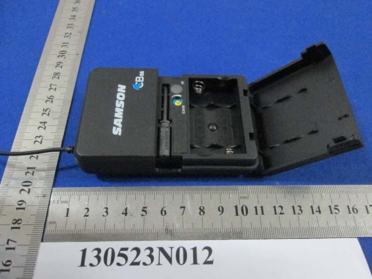
Click to zoom
Application Details
- Equipment Class
- TNT - Licensed Non-Broadcast Transmitter Worn on Body
- Date of Grant
- Jul 21, 2013
- Application Purpose
- Original Equipment
- Date of Application
- Jul 21, 2013
- Equipment Note
- Belt Pack Transmitter
- Frequency Range
- 638.12500000 - 661.97500000
- Company
- Sam Ash Music Corporation
- Country
- United States
Documents & Files
Document Text
Text extracted from the exhibit documents filed with the FCC. Open a document above to read the original.
Users Manual
OWNER'S MANUAL 16-CHANNEL TRUE DIVERSITY UHF WIRELESS SYSTEM Copyright 2013, Samson Technologies Corp. v1.2 Samson Technologies Corp. 45 Gilpin Ave Hauppauge, NY 11788 www.samsontech.com Important Safety Information CAUTION: TO REDUCE THE RISK OF ELECTRIC SHOCK, DO NOT REMOVE COVER (OR BACK). NO USER-SERVICEABLE PARTS IN- SIDE. REFER SERVICING TO QUALIFIED SERVICE PERSONNEL. This lightning flash with arrowhead symbol within an equilateral triangle is intended to alert the user to the presence of non-insulated “danger- ous voltage” within the product’s enclosure that may be of sufficient magnitude to constitute a risk of electric shock. The exclamation point within an equilateral triangle is intended to alert the user to the presence of important operating and maintenance in- structions in the literature accompanying the appliance. If you want to dispose this product, do not mix it with general household waste. There is a separate collection system for used electronic products in accordance with legislation that requires pr oper tr eatment, recovery and recycling. Private household in the 25 member states of the EU, in Switzerland and Norway may return their used electronic products free of charge to designated collection facilities or to a retailer (if you purchase a similar new one). For Countries not mentioned above, please contact your local authorities for a correct method of disposal. By doing so you will ensure that your disposed product undergoes the necessary treatment, recovery and recycling and thus prevent potential negative effects on the environment and human health. ATTENTION RISQUE D’ÉLECTROCUTION ! NE PAS OUVRIR ! WARNING TO PREVENT FIRE OR SHOCK HAZARD. DO NOT USE THIS PLUG WITH AN EXTENSION CORD, RECEPTACLE OR OTHER OUTLET UNLESS THE BLADES CAN BE FULLY INSERT- ED TO PREVENT BLADE EXPOSURE. TO PREVENT FIRE OR SHOCK HAZARD. DO NOT EXPOSE THIS APPLIANCE TO RAIN OR MOISTURE. TO PREVENT ELECTRICAL SHOCK, MATCH WIDE BLADE PLUG TO WIDE SLOT AND FULLY INSERT. Important Safety Information 1. Read these instructions. 2. Keep these instructions. 3. Heed all warnings. 4. Follow all instructions. 5. Do not use this apparatus near water. 6. Clean only with dry cloth. 7. Do not block any ventilation open- ings. Install in accordance with the manufacturer’s instructions. 8. Do not install near any heat sourc- es such as radiators, heat registers, stoves, or other apparatus (includ- ing amplifiers) that produce heat. 9. Do not defeat the safety purpose of the polarized or grounding type plug. A polarized plug has two blades with one wider than the other. A grounding type plug has two blades and a third ground- ing prong. The wide blade or the third prong are provided for your safety. If the provided plug does not fit into your outlet, consult an electrician for replacement of the obsolete outlet. 10. Protect the power cord from being walked on or pinched particularly at the plugs, convenience recep- tacles, and at the point where they exit from the apparatus. 11. Only use attachments/accessories specified by the manufacturer. 12. Use only with the cart, stand, tripod, bracket, or table specified by the manufacturer, or sold with the apparatus. When a cart is used, use caution when moving the cart/apparatus combination to avoid injury from tip-over. 13. Unplug the apparatus during light- ening storms, or when unused for long periods of time. 14. Refer all servicing to qualified per- sonnel. Service is required when the apparatus has been damaged in any way, such as power supply cord or plug is damaged, liquid has been spilled or objects have fallen into the apparatus has been exposed to rain or moisture, does not operate normally, or has been dropped. 15. This appliance shall not be exposed to dripping or splashing water and that no object filled with liquid such as vases shall be placed on the apparatus. 16. Caution-to prevent electrical shock, match wide blade plug wide slot fully insert. 17. Please keep a good ventilation en- vironment around the entire unit. 18. The direct plug-in adapter is used as disconnect device, the discon- nect device shall remain readily operable. 19. Batteries (battery pack or batteries installed) shall not be exposed to excessive heat such as sunshine, fire or the like. 5 Concert 88 Wireless System Table of Contents Introduction. . . . . . . . . . . . . . . . . . . . . . . . . . . 6 System Features . . . . . . . . . . . . . . . . . . . . . . . . . 7 System Components . . . . . . . . . . . . . . . . . . . . . . . 7 Guided Tour - CR88 Receiver . . . . . . . . . . . . . . . . . . 8 Guided Tour - CB88 Belt Pack Transmitter . . . . . . . . . . . .10 Guided Tour - CH88 Handheld Transmitter . . . . . . . . . . . .12 Quick Start - Single System Setup . . . . . . . . . . . . . . . .13 Quick Start - Multiple System Setup . . . . . . . . . . . . . . .17 Rack Mounting . . . . . . . . . . . . . . . . . . . . . . . . .19 Concert 88 Channel Plans . . . . . . . . . . . . . . . . . . . .20 Troubleshooting . . . . . . . . . . . . . . . . . . . . . . . . .21 Specifications . . . . . . . . . . . . . . . . . . . . . . . . . .22 6 Congratulations on purchasing the Samson Concert 88 wireless system. The Concert 88 is the ideal solution for the active performer who needs a reliable, great sounding system for wireless applications. Featuring simple operation, with 16 available chan- nels and infrared set for the transmitter channel, the Concert 88 can quickly be up and running out of the box. The Concert 88 system ensures clear, interruption-free performance by combining tone-key with auto-mute. This configuration allows only the transmitter’s audio to pass through the receiver, and mutes the output if there is any interference. The Concert 88 comes in four configurations. The vocal handheld system includes the CH88 handheld transmitter and Q7 dynamic microphone capsule. The CB88 belt pack system can be configured with either the HS5 headset microphone, LM5 lavalier microphone, or…
Text truncated - open the document above for the full version.
Users Manual
15 Concert 88 Wireless System Quick Start - Single System Setup This device complies with Part 15 of the FCC Rules. Operation is subject to the following two conditions: (1) This device may not cause harmful interference, and (2) this device must accept any interference received, including interference that may cause undesired operation. FREQ: 542-566MHz This device complies with Part 15 of the FCC Rules. Operation is subject to the following two conditions: (1) This device may not cause harmful interference, and (2) this device must accept any interference received, including interference that may cause undesired operation. FREQ: 542-566MHz 3. Plug in receiver4. Turn on receiver 5. Plug receiver into audio system6. Press Select button to change channel9. Press and hold SELECT button to IR set10. Adjust Volume control7. Install batteries8. Press button on transmitter to turn on 9. Press and hold Select button to IR set7. Install batteries8. Turn on belt pack transmitter This device complies with Part 15 of the FCC Rules. Operation is subject to the following two conditions: (1) This device may not cause harmful interference, and (2) this device must accept any interference received, including interference that may cause undesired operation. FREQ: 542-566MHz This device complies with Part 15 of the FCC Rules. Operation is subject to the following two conditions: (1) This device may not cause harmful interference, and (2) this device must accept any interference received, including interference that may cause undesired operation. FREQ: 542-566MHz 3. Plug in receiver4. Turn on receiver 5. Plug receiver into audio system6. Press Select button to change channel9. Press and hold SELECT button to IR set10. Adjust Volume control7. Install batteries8. Press button on transmitter to turn on 9. Press and hold Select button to IR set7. Install batteries8. Turn on belt pack transmitter Position the transmitter about 6-12" (15-30 cm) from the front of the CR88 with the transmitter's IR window facing the IR transmitter on the front panel of the CR88 receiver. This device complies with Part 15 of the FCC Rules. Operation is subject to the following two conditions: (1) This device may not cause harmful interference, and (2) this device must accept any interference received, including interference that may cause undesired operation. FREQ: 542-566MHz This device complies with Part 15 of the FCC Rules. Operation is subject to the following two conditions: (1) This device may not cause harmful interference, and (2) this device must accept any interference received, including interference that may cause undesired operation. FREQ: 542-566MHz 3. Plug in receiver4. Turn on receiver 5. Plug receiver into audio system6. Press Select button to change channel9. Press and hold SELECT button to IR set10. Adjust Volume control7. Install batteries8. Press button on transmitter to turn on 9. Press and hold Select button to IR set7. Install batteries8. Turn on belt pack transmitter This device complies with Part 15 of the FCC Rules. Operation is subject to the following two conditions: (1) This device may not cause harmful interference, and (2) this device must accept any interference received, including interference that may cause undesired operation. FREQ: 542-566MHz This device complies with Part 15 of the FCC Rules. Operation is subject to the following two conditions: (1) This device may not cause harmful interference, and (2) this device must accept any interference received, including interference that may cause undesired operation. FREQ: 542-566MHz 3. Plug in receiver4. Turn on receiver 5. Plug receiver into audio system6. Press Select button to change channel9. Press and hold SELECT button to IR set10. Adjust Volume control7. Install batteries8. Press button on transmitter to turn on 9. Press and hold Select button to IR set7. Install batteries8. Turn on belt pack transmitter Press and hold the CR88 SELECT button to set the transmitter to the same channel as the receiver via infrared transmission Press the SELECT button on the front of the CR88 receiver to choose an available channel. The channel number will increase by one digit, from 0-9 then A-F. Once the last channel has been reached, the count will cycle back to 0. 16 Turn on your connected amplifier or mixer, but keep the volume all the way down. Set the Volume knob on the CR88 fully clockwise (to its “10” setting). This is unity gain. Speak or sing into the microphone, or if you are using the transmitter with a con- nected instrument, play the instrument at normal performance level. Slowly raise the volume of your amplifier or mixer until the desired level is reached. If you find the system has noticeable dropouts, reduced overall working range, or unexpected noise bursts, change the operating channel of the system using the steps above. This device complies with Part 15 of the FCC Rules. Operation is subject to the following two conditions: (1) This device may not cause harmful interference, and (2) this device must accept any interference received, including interference that may cause undesired operation. FREQ: 542-566MHz This device complies with Part 15 of the FCC Rules. Operation is subject to the following two conditions: (1) This device may not cause harmful interference, and (2) this device must accept any interference received, including interference that may cause undesired operation. FREQ: 542-566MHz 3. Plug in receiver4. Turn on receiver 5. Plug receiver into audio system6. Press Select button to change channel9. Press and hold SELECT button to IR set10. Adjust Volume control7. Install batteries8. Press button on transmitter to turn on 9. Press and hold Select button to IR set7. Install batteries8. Turn on belt pack transmitter This device complies with Part 15 of the FCC Rules. Operation is subject to the following two conditions: (1) This device may not cause harmful interference, and (2) this device must accept any interference received, in…
Text truncated - open the document above for the full version.
External Photos
Bureau Veritas Shenzhen Co., Ltd. Dongguan Branch No. 34, Chenwulu Section, Guantai Rd., Houjie Town, Dongguan City, Guangdong 523942, China Tel.: +86 769 8593 5656 Fax: +86 769 8593 1080 Email: [email protected] Page 1 of 3 Report Version 1 Reference No.: 130523N012-1 PHOTOGRAPHS OF THE EUT’S EXTERNAL VIEWS Bureau Veritas Shenzhen Co., Ltd. Dongguan Branch No. 34, Chenwulu Section, Guantai Rd., Houjie Town, Dongguan City, Guangdong 523942, China Tel.: +86 769 8593 5656 Fax: +86 769 8593 1080 Email: [email protected] Page 2 of 3 Report Version 1 Reference No.: 130523N012-1 Bureau Veritas Shenzhen Co., Ltd. Dongguan Branch No. 34, Chenwulu Section, Guantai Rd., Houjie Town, Dongguan City, Guangdong 523942, China Tel.: +86 769 8593 5656 Fax: +86 769 8593 1080 Email: [email protected] Page 3 of 3 Report Version 1 Reference No.: 130523N012-1
ID Label/Location Info
CB88 FCC ID label :
Internal Photos
Bureau Veritas Shenzhen Co., Ltd. Dongguan Branch No. 34, Chenwulu Section, Guantai Rd., Houjie Town, Dongguan City, Guangdong 523942, China Tel.: +86 769 8593 5656 Fax: +86 769 8593 1080 Email: [email protected] Page 1 of 4 Report Version 1 Reference No.: 130523N012-1 PHOTOGRAPHS OF THE EUT’S INTERNAL VIEWS Bureau Veritas Shenzhen Co., Ltd. Dongguan Branch No. 34, Chenwulu Section, Guantai Rd., Houjie Town, Dongguan City, Guangdong 523942, China Tel.: +86 769 8593 5656 Fax: +86 769 8593 1080 Email: [email protected] Page 2 of 4 Report Version 1 Reference No.: 130523N012-1 Bureau Veritas Shenzhen Co., Ltd. Dongguan Branch No. 34, Chenwulu Section, Guantai Rd., Houjie Town, Dongguan City, Guangdong 523942, China Tel.: +86 769 8593 5656 Fax: +86 769 8593 1080 Email: [email protected] Page 3 of 4 Report Version 1 Reference No.: 130523N012-1 Bureau Veritas Shenzhen Co., Ltd. Dongguan Branch No. 34, Chenwulu Section, Guantai Rd., Houjie Town, Dongguan City, Guangdong 523942, China Tel.: +86 769 8593 5656 Fax: +86 769 8593 1080 Email: [email protected] Page 4 of 4 Report Version 1 Reference No.: 130523N012-1
RF Exposure Info
Bureau Veritas Shenzhen Co., Ltd. Dongguan Branch Tel: +86 769 8593 5656 Fax: +86 769 8593 1080 Email: [email protected] No SAR justification for FCC ID : CCRCB88 Following FCC KDB 447498 D01 “General SAR test exclusion guidance” The corresponding SAR Exclusion Threshold condition, listed below: 1) The 1‐g and 10‐g SAR test exclusion thresholds for 100 MHz to 6 GHz at test separation distances ≤ 50 mm are determined by: [(max. power of channel, including tune‐up tolerance, mW)/(min. test separation distance, mm)] ∙[√f(GHz)] ≤ 3.0 for 1‐g SAR and ≤ 7.5 for 10‐g extremity SAR,16 where ¾ f(GHz) is the RF channel transmit frequency in GHz ¾ Power and distance are rounded to the nearest mW and mm before calculation ¾ The result is rounded to one decimal place for comparison The test exclusions are applicable only when the minimum test separation distance is ≤ 50 mm and for transmission frequencies between 100 MHz and 6 GHz. When the minimum test separation distance is < 5 mm, a distance of 5 mm is applied to determine SAR test exclusion. 2) At 100 MHz to 6 GHz and for test separation distances > 50 mm, the SAR test exclusion threshold is determined according to the following: a) [Threshold at 50 mm in step 1) + (test separation distance ‐ 50 mm)∙( f(MHz)/150)] mW, at 100MHz to 1500 MHz b) [Threshold at 50 mm in step 1) + (test separation distance ‐ 50 mm)∙10] mW at > 1500 MHz and ≤ 6 GHz 3) At frequencies below 100 MHz, the following may be considered for SAR test exclusion. a) The threshold at the corresponding test separation distance at 100 MHz in step 2) is multiplied by [1 + log(100/f(MHz))] for test separation distances > 50 mm and < 200 mm. b) The threshold determined by the equation in a) for 50 mm and 100 MHz is multiplied by ½ for test separation distances ≤ 50 mm. c) SAR measurement procedures are not established below 100 MHz. When SAR test exclusion cannot be applied, a KDB inquiry is required to determine SAR evaluation requirements for any test results to be acceptable. Smallest distance from the antenna and radiating structures or outer surface of the device The minimum test separation distance is determined by the smallest distance from the antenna and radiating structures or outer surface of the device, according to the host form factor, exposure conditions and platform requirements, to any part of the body or extremity of a user or bystander. Bureau Veritas Shenzhen Co., Ltd. Dongguan Branch Tel: +86 769 8593 5656 Fax: +86 769 8593 1080 Email: [email protected] SAR Test Exclusion Thresholds Channel and Mode Frequency (MHz) Maximum source‐based time averaged conducted output power including tune‐up tolerance (mW) Minimum separation distance (mm) Result of Eq. 1 Limit for 1‐g SAR Limit for 10‐g extremity SAR Verdict CH 0 542.125 10.02 mW 5mm 1.476 3.0 7.5 Exempt from SAR Ch 8 554.000 8.30 mW 5mm 1.235 3.0 7.5 Exempt from SAR CH F 565.975 5.43 mW 5mm 0.817 3.0 7.5 Exempt from SAR Channel and Mode Frequency (MHz) Maximum source‐based time averaged conducted output power including tune‐up tolerance (mW) Minimum separation distance (mm) Result of Eq. 1 Limit for 1‐g SAR Limit for 10‐g extremity SAR Verdict CH 0 638.125 10.84 mW 5mm 1.732 3.0 7.5 Exempt from SAR Ch 8 650.000 9.55 mW 5mm 1.540 3.0 7.5 Exempt from SAR CH F 661.975 7.29 mW 5mm 1.187 3.0 7.5 Exempt from SAR Conclusion Since Source‐base time average power is below SAR test exclusion power thresholds, the SAR evaluation is not required.
Test Report
Bureau Veritas Shenzhen Co., Ltd. Dongguan Branch No. 34, Chenwulu Section, Guantai Rd., Houjie Town, Dongguan City, Guangdong 523942, China Tel: +86 769 8593 5656 Fax: +86 769 8593 1080 Email: [email protected] Page 1 on 48 Report Version 1 Test Report No.: FC130523N012-1 TEST REPORT Applicant Sam Ash Music Corporation Address 262 Duffy Avenue Hicksville, NY 11801 United States Manufacturer or Supplier Sam Ash Music Corporation Address 262 Duffy Avenue Hicksville, NY 11801 United States Product Concert 88 Multi Channel UHF Wireless Brand Name SAMSON Model CB88 Additional Model & Model Difference N/A Date of tests May 25 ~ Jun. 21, 2013 The tests have been carried out according to the requirements of the following standards: FCC Part 74, Subpart H (Section 74.861e) )) ) CONCLUSION: The submitted sample was found to COMPLY with the test requirement Prepared by Glyn He Project Engineer / EMC Department Approved by Sam Tung Manager / EMC Department This report is for your exclusive use. Any copying or replication of this report to or for any other person or entity, or use of our name or trademark, is permitted only with our prior written permission. This report sets forth our findings solely with respect to the test samples identified herein. The results set forth in this report are not indicative or representative of the quality or characteristics of the lot from which a test sample was taken or any similar or identical product unless specifically and expressly noted. Our report includes all of the tests requested by you and the results thereof based upon the information that you provided to us. You have 60 days from date of issuance of this report to notify us of any material error or omission caused by our negligence, provided, however, that such notice shall be in writing and shall specifically address the issue you wish to raise. A failure to raise such issue within the prescribed time shall constitute your unqualified acceptance of the completeness of this report, the tests conducted and the correctness of the report contents. Unless specific mention, the uncertainty of measurement has been explicitly taken into account to declare the compliance or non-compliance to the specification Bureau Veritas Shenzhen Co., Ltd. Dongguan Branch No. 34, Chenwulu Section, Guantai Rd., Houjie Town, Dongguan City, Guangdong 523942, China Tel: +86 769 8593 5656 Fax: +86 769 8593 1080 Email: [email protected] Page 2 on 48 Report Version 1 Test Report No.: FC130523N012-1 TABLE OF CONTENTS RELEASE CONTROL RECORD ............................................................................................................ 4 1. SUMMARY OF TEST RESULTS.................................................................................................... 5 2. MEASUREMENT UNCERTAINTY ................................................................................................. 5 3. GENERAL INFORMATION ............................................................................................................ 6 3.1 GENERAL DESCRIPTION OF EUT ........................................................................................... 6 3.2 DESCRIPTION OF TEST MODES ............................................................................................. 6 3.3 GENERAL DESCRIPTION OF APPLIED STANDARDS ............................................................ 7 3.4 DESCRIPTION OF SUPPORT UNITS ....................................................................................... 7 4. TEST TYPES AND RESULTS........................................................................................................ 8 4.1 CONDUCTED POWER OUTPUT MEASUREMENT.................................................................. 8 4.1.1 LIMITS OF CONDUCTED POWER OUTPUT MEASUREMENT ..................................... 8 4.1.2 TEST INSTRUMENTS....................................................................................................... 8 4.1.3 TEST PROCEDURES ....................................................................................................... 8 4.1.4 TEST SETUP..................................................................................................................... 9 4.1.5 EUT OPERATING CONDITIONS ...................................................................................... 9 4.1.6 TEST RESULTS ................................................................................................................ 9 4.2 SPURIOUS RADIATION MEASUREMENT.............................................................................. 10 4.2.1 LIMITS OF SPURIOUS RADIATION MEASUREMENT .................................................. 10 4.2.2 TEST INSTRUMENTS..................................................................................................... 10 4.2.3 TEST PROCEDURE.........................................................................................................11 4.2.4 TEST SETUP................................................................................................................... 12 4.2.5 TEST RESULTS .............................................................................................................. 13 4.3 CONDUCTED SPURIOUS MEASUREMENT .......................................................................... 19 4.3.1 LIMITS OF CONDUCTED SPURIOUS MEASUREMENT .............................................. 19 4.3.2 TEST INSTRUMENTS..................................................................................................... 19 4.3.3 TEST PROCEDURE........................................................................................................ 19 4.3.4 TEST SETUP................................................................................................................... 19 4.3.5 TEST RESULTS .............................................................................................................. 20 4…
Text truncated - open the document above for the full version.
Test Setup Photos
Set-up for radiated emission test
Contact Information
Applicant
Don Albanese
Test Firm
Bureau Veritas Shenzhen Co., Ltd. Dongguan BranchAlec Hu
Technical Specifications
| # | Rule Parts | Frequency Range | Power Output | Emission | Tolerance |
|---|---|---|---|---|---|
| 2 | 74 | 638.125 MHz - 661.975 MHz | 11.00 mW | 95K5F3E | 0.00032 % |
Other Applications from Sam Ash Music Corporation
CCRCBXD2
Jan 11, 2024TRANSMITTER
Equipment Class
PUT - Part 15 Unlicensed PCS portable Tx worn on body
CCRCHXD2
Jan 11, 2024TRANSMITTER
Equipment Class
PUF - Part 15 Unlicensed PCS portable Tx held to face
CCRET100
Jan 09, 2024ET100 UHF Transmitter
Equipment Class
TLD - Licensed LPAS Device
CCRXP106W
May 20, 2020Bluetooth Speaker
Equipment Class
DSS - Part 15 Spread Spectrum Transmitter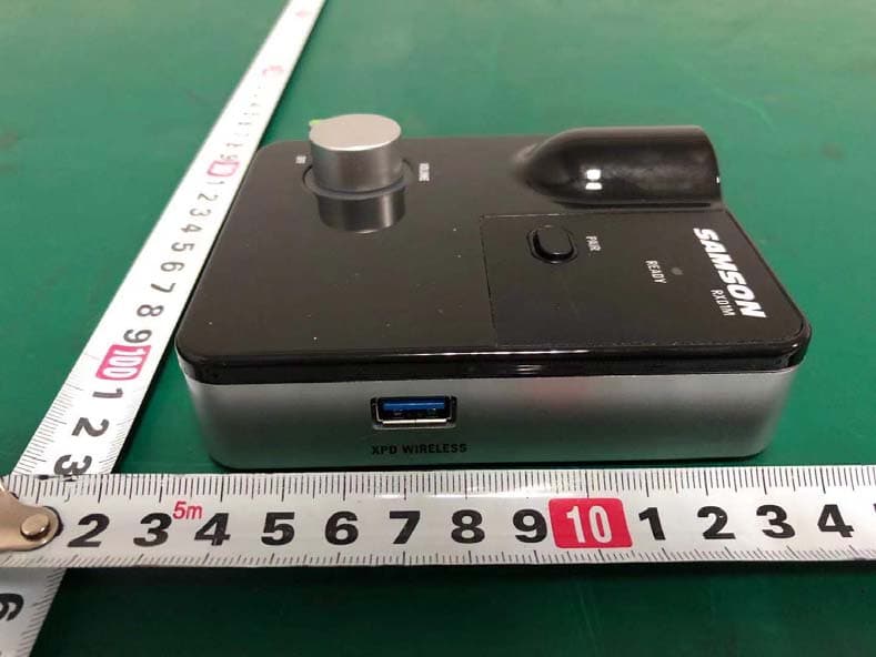
CCRRXD1M
Mar 18, 20202.4G Wireless microphone Receiver
Equipment Class
DXX - Part 15 Low Power Communication Device Transmitter