CCRHT5Wireless Microphone
Sam Ash Music Corporation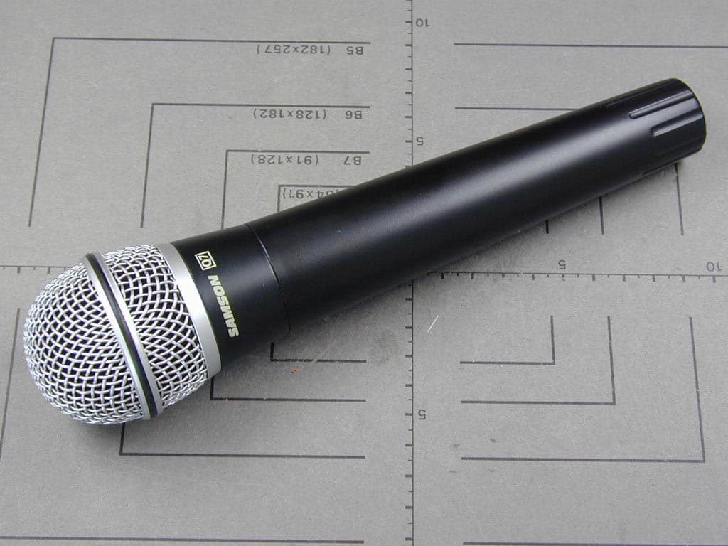
Click to zoom
Application Details
- Equipment Class
- TNF - Licensed Non-Broadcast Transmitter Held to Face
- Date of Grant
- Jul 08, 2003
- Application Purpose
- Original Equipment
- Date of Application
- Jul 08, 2003
- Equipment Note
- Wireless Microphone
- Frequency Range
- 175.00000000 - 213.20000000
- Company
- Sam Ash Music Corporation
- Country
- United States
Documents & Files
Document Text
Text extracted from the exhibit documents filed with the FCC. Open a document above to read the original.
Users Manual
WIRELESS AND WIRELESS SYSTEM TRUE DIVERSITY WIRELESS SYSTEM Copyright 2002, Samson Technologies Corp. Printed September 2002 Samson Technologies Corp. 575 Underhill Blvd. P.O. Box 9031 Syosset, NY 11791-9031 Phone: 1-800-3-SAMSON (1-800-372-6766) Fax: 516-364-3888 Table of Contents Introduction 3 Guided Tour - SR55 Receiver Front Panel 5 Guided Tour - SR55 Receiver Rear Panel 6 Guided Tour - SR5 Receiver Front Panel 7 Guided Tour - SR5 Receiver Rear Panel 8 Guided Tour - ST5 Transmitter 9 Guided Tour - HT5 Transmitter 11 Setting Up and Using Your Stage 55 Series / Stage 5 Series System 12 Appendix B: Carrying Case 15 Specifications 16 3 Introduction Congratulations on purchasing the Samson Stage 55 Series or Stage 5 Series Wireless System! Although this product is designed for easy operation, we suggest you first take some time to go through these pages so you can fully understand how we’ve implemented a number of unique features. Every wireless system consists of at least two components—a transmitter and a receiver, both of which must be tuned to the same channel (that is, the same radio frequency) in order to operate correctly.* The Samson Stage 55 Series or Stage 5 Series system you have purchased operates in the 174.0 - 216.0 MHz frequency range and contains either a SR55 or SR5 receiver as well as one of the following transmitters: a ST5 belt-pack transmitter (for lavaliere microphone or headset applications); a ST5 belt-pack transmitter (for instrument applications); or a HT5 hand-held microphone transmitter. For convenience and security, the Stage 55 Series and Stage 5 Series system is packaged in a custom impact-resistant polypropylene plastic carrying case that provides room for all components (see Appendix B for more information). The ST5L beltpack transmitter provides a locking 3.5 mm mini-phone jack for connection to the various Stage series transmitters including: LM5 - Lavaliere condenser microphone HS5 - Headset condenser microphone GC5 - Heavy-duty Guitar/Instrument cable The HT5 hand-held microphone transmitter is equipped with the Samson Q7 neodymium dynamic microphone element. * Your receiver and transmitter have been factory preset to utilize the same channel. The SR5 receiver provided with the STAGE 5 Series wireless system utilizes non-diversity technology, incorporating a single antenna for ease of use and minimal cost. The SR55 receiver provided with the Stage 55 Series system utilizes an advanced technology called “Diversity,” whereby a single chassis houses two antennas (called “Antenna A” and “Antenna B”) and a receiver circuit. An advanced circuit design continuously scans RF sig- nals from the two antennas and determines which one has the clearest and strongest reception, automatically (and silently) switching that signal to the receiver. This allows you to maintain the wireless communication link over a much broader area range than would be allowed by a receiver utilizing a single antenna and also virtually eliminates multipath dropouts, interference and phase cancellation problems. In addition, special sample-and- hold linking circuitry ensures that correct phase correlation is maintained at all times, with no noise or pops during antenna switching. The result is performance which exceeds that of conventional non-diversity systems and the highest quality audio fidelity available in any wireless system. Finally, the provision of a noise reduction circuit produces crystal-clear sound with minimized background noise and hiss. 4 Introduction In this manual, you’ll find a more detailed description of the features of your Stage 55 Series or Stage 5 Series system, as well as a guided tour through all components, step- by-step instructions for setting up and using your system and full specifications. If your Stage 55 Series or Stage 5 Series system was purchased in the United States, you’ll also find a warranty card enclosed—don’t forget to fill it out and mail it! This will enable you to receive online technical support and will allow us to send you updated information about other Samson products in the future. If your Stage 55 Series or Stage 5 Series system was purchased outside of the United States, contact your local distributor for warranty details. SPECIAL NOTE for U.S. purchasers: Should your Stage 55 Series or Stage 5 Series sys- tem ever require servicing, a Return Authorizationnumber (RA) is necessary. Without this number, the unit will not be accepted. Please call Samson at 1-800-372-6766 for a Return Authorization number prior to shipping your unit. Please retain the original packing materials and, if possible, return the unit in its original carton and packing materials. If your Stage 55 Series or Stage 5 Series system was purchased outside of the United States, contact your local distributor for servicing information. 5 Guided Tour - SR55 Front Panel 1: Antennas (A and B)- The antenna mountings allow full rotation for optimum placement. In normal operation, both Antenna A (the antenna on the left) and Antenna B (the antenna on the right) should be placed in a vertical position. Both antennas can be folded inward for convenience when transporting the SR55. See the “Setting Up and Using Your Stage 55 Series / Stage 5 Series System” section on page 12 in this manual for more information about antenna positioning. 2: Volume control - This knob sets the level of the audio signal being output through both the balanced and unbalanced output jacks on the rear panel. Reference level is obtained when the knob is turned fully clockwise. 3: Audio Meter- This “ladder” display (similar to the VU bar meter used on audio devices) indicates the strength of the incoming audio signal. When the “0” segment is lit, the incom- ing signal is optimized at unity gain; when the “+6” segment is lit, the signal is overloading. When only the left-most “-20” segment is lit, the incoming signal is at just 10% of optimum strength. If no segments are lit, little or no signal is bein…
Text truncated - open the document above for the full version.
Cover Letter(s)
Request for Confidentiality 27 May 2003 American Telecommunications Certification Body, Inc. 6731 Whittier Avenue Suite C110 McLean, VA 22101 RE: Certification Application FCC ID: CCRHT5 Please be advised that the following information is to be held confidential and behalf of Sam Ash Music Corporation: • Schematics • Block Diagram • Technical Description • Parts Lists The application contains technical information which Sam Ash Music Corporation deems to be trade secrets and proprietary. If made public, the information might be used to the disadvantage of the applicant in the market place. Thank you for your attention to this matter.
Cover Letter(s)
EMV-Prüfzentrum EMI/EMC-Testcenter Hausanschrift: Sparkasse (BLZ 742 500 00) 14 076 Handelsregister Straubing Äussere Frühlingstrasse 45 y D-94315 Straubing Deutsche Bank (BLZ 750 700 13) 9 855 255 HRB-Nr. 9302 Telefon (0 94 21) 55 22-0 Dresdner Bank (BLZ 700 800 00) 0 803 965 300 Geschäftsführer: Telefax (0 94 21) 55 22-99 HypoVereinsbank (BLZ 742 200 75) 2 615 649 Johann Roidt, Manfred Amann [email protected] y http://www.senton.de Postgiro Nürnberg (BLZ 760 100 85) 1 778 87 857 Senton GmbH y Äussere Frühlingstrasse 45 y D-94315 Straubing Timothy R. Johnson American TCB 2003-07-05 In reference to FCC ID: CCRHT5 1) The FCC Label has been corrected and filed through ATCB website. 2) The operationial description has been corrected and filed through ATCB website. 3) The nominal frequency range of this device is 174 – 216 MHz. The lowest channel available is 175.000 MHz. The highest channel available is 213.2 MHz. This insures that no emission falls outside the authorized band. 4) The emission designator 130KF3E has been calculated from maximum deviation and frequency measured. The applicant declared that the transmitter works linear with low distortion up to 15 kHz deviation. This is the maximum signal which can be expected from the microphone. The emission designator in the manual has been changed accordingly. 5) The reference to part 90 has been deleted from the manual. 6) The unit has been retested with a temporary connector at the RF output with the antenna disconnected for conducted data and the test report has been modified accordingly. 7) The power level in the manual has been changed to 5 mW for the US version in order to meet actual values. 8) This typographic error has been corrected in the report. 9) This issue has been corrected as well. 10) a) DC voltages/currents applied into the several elements of the final radio frequency amplifying device according to section 2.1033 ( c ) (8) The input power to the final stage (TR7) was measured with a fresh 9 V battery. Input power for 9.0 V operation (9.0V) (4.2 mA) = 37.8 milliWatts. b) Tune up procedure has been added to this submission. c) Description of circiutry and devices has been added to the operational description. 11) Correction factors have been added to the modified test report. 12) The receiver will be covered by DoC compliance route. Senton GmbH Johann Roidt
Cover Letter(s)
American Telecommunications Certification Body Inc. 6731 Whittier Ave, McLean, VA 22101 June 10, 2003 RE: Sam Ash Music Corporation FCC ID: CCRHT5 I have a few comments on the above referenced Application. 1) The FCC Label shows "FCC ID CCRHT5". Note that the colon is missing after the words FCC ID. Please correct to "FCC ID: CCRHT5". 2) The operational description provided does not appear to include information on this device. Please correct. 3) The test report and 731 form state the device operates from 174 - 216 MHz which is given in Part 74 for low power stations. However the users manual states 174.6-213.2 (front) and 173.80 - 213.20 (back) which falls outside this band. Note that 74.861 states that low power auxiliary transmitters not required to operate on specific carrier frequencies shall operate sufficiently within the authorized frequency band edges to insure the emission bandwidth falls entirely within the authorized band.. Please correct any incorrect exhibits and provide the actual list of transmitting frequencies to show compliance with this section. 4) The emission designator given in the manual (80KF3E) does not match the 731 from and test report (130KF3E). Additionally the users manual mentions a peak deviation of 15 kHz, compared with 50 kHz given in the report. Please explain and correct the affected exhibits. 5) The users manual mentions Part 74 and Part 90, while this application appears to only be for Part 74. Please explain. 6) The users manual states the device is capable of 20 mW (+13 dBm), but only -21.28 dBm was measured using the substitution method. This is a large unexpected difference of 41.28 dB. Please explain. Additionally, please note that the technical requirements of 74.861 mention measuring at the output terminals so a direct connection method is the preferred method for this section of the rules if it can be performed. Note that the grant will list the direct connection results if these can be provided, otherwise the ERP power will have to be used. 7) Note that the European version only operates at 2 mW, which is 10 dB lower than the U.S. version. If the device provided in this application was not properly operating at full output power expected of 20 mW, then retesting of spurious emissions will be required also due to the increase of output power. 8) Page 22 of the test report states testing was performed to 1 GHz, while the other tables state 2 GHz. Please explain. 9) The test report should reference the most recent published version of Part 2/15/74, for example October 2002. Additionally, Part 15 Subpart H given on page 4 & 32 of the test report is not valid. Please correct. 10) Please provide: a) DC voltages & /currents applied into the several elements of the final radio frequency amplifying device for normal operation over the power range b) Tune up procedure over power range c) Description of all circuitry and devices provided for determining and stabilizing frequency, for suppression of spurious radiation, for limiting modulation, and for limiting power. --- Continued on Next Page --- z Page 2June 10, 2003 11) Please provide information regarding the conversion factor for substitution methods as you have in past reports. 12) The test report includes data for the receiver portion of the device. Note that a separate application must submitted for certification of the RX, or alternatively a DoC performed by an appropriately accredited test facility. The RX information will be ignored within this application, however please comment on what compliance route is being used for the RX (separate certification or DoC). Timothy R. Johnson Examining Engineer mailto: [email protected] The items indicated above must be submitted before processing can continue on the above referenced application. Failure to provide the requested information may result in application termination. Correspondence should be considered part of the permanent submission and may be viewed from the Internet after a Grant of Equipment Authorization is issued. Please do not respond to this correspondence using the email reply button. In order for your response to be processed expeditiously, you must submit your documents through the AmericanTCB.com website. Also, please note that partial responses increase processing time and should not be submitted. Any questions about the content of this correspondence should be directed to the sender.
External Photos
EMV-Prüfzentrum EMI/EMC-Testcenter FCC IC CCRHT5 EMV-Prüfzentrum EMI/EMC-Testcenter FCC IC CCRHT5
ID Label/Location Info
EMV-Prüfzentrum EMI/EMC-Testcenter FCC IC CCRHT5
Internal Photos
EMV-Prüfzentrum EMI/EMC-Testcenter FCC ID: CCRHT5 EMV-Prüfzentrum EMI/EMC-Testcenter FCC ID: CCRHT5
Operational Description
FCC ID: CCRHT5 Tune-up Procedure Tune up procedure over power range according to section 2.1033 ( c ) (9) 1. Pick up the transmitter RF signal by an inductive coupling loop placed close to the unit. 2. Connect the pick up device to the sensitive input of a radio communication tester 3. Adjust T1 for proper transmitter frequency 4. Adjust T4, T5, VC1 and VC2 for maximum output power 5. Adjust L3, L4, L6, L7, L8, for maximum output power while keeping harmonics at minimum. 6. Repeat steps d) and e) if necessary
Test Report
EMV-Prüfzentrum EMI/EMC-Testcenter FCC-ID: CCRHT5 Test Report No. 56408-30116 Page 1 of 33 Pages Straubing, 27 March 2003 T E S T - R E P O R T No. 56408-30116 for STAGE 55 Wireless Audio System Applicant: SAMSON Technologies Corp. Purpose of testing: To show compliance with FCC Code of Federal Regulations, Part 74 Subpart H, section 74.861 Note: The test data of this report relate only to the individual item which has been tested. This report shall not be reproduced except in full extent without the written approval of the testing laboratory. EMV-Prüfzentrum EMI/EMC-Testcenter FCC-ID: CCRHT5 Test Report No. 56408-30116 Page 2 of 33 Pages Table of Contents 1. Administrative Data.....................................................................................3 2. Identification of Test Laboratory .................................................................4 3. Operation Mode of EUT..............................................................................5 4. Configuration ..............................................................................................6 5. Measuring Methods ....................................................................................7 5.1. Maximum Transmitter Power (§ 2.1046 (a), 74.861 (e)) ......................7 5.2. Mean power of emissions 30 MHz – 8.2GHz (§ 74.861.e.6.iii)........................................................................................8 5.3. Radiated Emission 1 GHz – 8.2 GHz (§ 74.861.e.6.iii) ........................9 5.4. Emission Masks (Occupied Bandwidth) § 2.1049 (c) (1)....................10 5.5. Audio Frequency Response, 2.1047 (a).............................................10 5.5. Audio Frequency Response, 2.1047 (a).............................................11 5.6. Modulation Limiting, § 2.1047 (b) .......................................................11 5.6. Modulation Limiting, § 2.1047 (b) .......................................................12 5.7. Frequency Stability (Temperature Variation), § 2.1055 (a) (1) .................................................................................................12 5.7. Frequency Stability (Temperature Variation), § 2.1055 (a) (1) .................................................................................................13 5.8. Frequency Stability (Voltage Variation), § 2.1055 (b) (1) ...................14 6. Equipment List ..........................................................................................15 7. Photographs Taken During Testing ..........................................................17 8. List of Measurements ...............................................................................19 9. Referenced Regulations ...........................................................................32 10. Charts taken during testing.......................................................................33 EMV-Prüfzentrum EMI/EMC-Testcenter FCC-ID: CCRHT5 Test Report No. 56408-30116 Page 3 of 33 Pages 1. Administrative Data Test item (EUT) Type designation STAGE 55 Serial number(s): 001 Type of equipment: Wireless Audio System Parts/accessories: HT5 Wireless Microphone, SR55 True Diversity Receiver FCC-ID: Technical data Frequency range 174-216 MHz Operational frequency 175.000 MHz, 199.600 MHz, 213.200 Mhz Type of modulation 130KF3E Pulse frequency N/A Pulse width N/A Antenna Integrated Power supply 9 V Battery Applicant: (full address) SAMSON Technologies Corp. 575 Underhill Blvd. Syosset, N.Y. 11791-9031, USA Contract identification: --- Contact person: Joan Wu Manufacturer: SAMSON Technologies Corp. Application details Receipt of EUT: 20 February 2003 Date of test: 25 March 2003 Note: Responsible for testing: Johann Roidt Responsible for test report: Johann Roidt EMV-Prüfzentrum EMI/EMC-Testcenter FCC-ID: CCRHT5 Test Report No. 56408-30116 Page 4 of 33 Pages 2. Identification of Test Laboratory DETAILS OF THE TEST LABORATORY COMPANY NAME: Senton GmbH EMI/EMC Test Center ADDRESS: Aeussere Fruehlingsstrasse 45 D-94315 Straubing Germany LABORATORY ACCREDITATION: DAR-Registration No. TTI-P-G 062/94-40 FCC TEST SITE LISTING INDUSTRY CANADA TEST SITE REGISTRATION IC 3050 NAME FOR CONTACT PURPOSES: Mr. Johann Roidt TELEPHONE: (+49) (0)9421 5522-0 FAX: (+49) (0)9421 5522-99 PERSONNEL INVOLVED IN THIS TEST REPORT TECHNICAL DIRECTOR: Mr. Johann Roidt RESPONSIBLE FOR TESTING: Mr. Johann Roidt RESPONSIBLE FOR TEST REPORT: Mr. Johann Roidt SUMMARY OF TEST RESULTS The tested sample complies with the requirements set forth in the Code of Regulations Part 74 Subpart H, Section § 74.861 of the Federal Communication Commission (FCC. EMV-Prüfzentrum EMI/EMC-Testcenter FCC-ID: CCRHT5 Test Report No. 56408-30116 Page 5 of 33 Pages 3. Operation Mode of EUT Transmitter operating continuously, full tests were performed on lowest, middle and highest RF channel. With battery supply 9.00 V DC EMV-Prüfzentrum EMI/EMC-Testcenter FCC-ID: CCRHT5 Test Report No. 56408-30116 Page 6 of 33 Pages 4. Configuration Configuration of the EUT Not applicable Cables connected to the EUT Not applicable Peripheral devices connected to the EUT Not applicable EMV-Prüfzentrum EMI/EMC-Testcenter FCC-ID: CCRHT5 Test Report No. 56408-30116 Page 7 of 33 Pages 5. Measuring Methods 5.1. Maximum Transmitter Power (§ 2.1046 (a), 74.861 (e)) 5.1.1. Conducted Maximum Transmitter Power Rules and Specifications: Sections 2.1046 (a) Guide: ANSI/TIA/EIA-603-1992, Paragraph 2.2.11 Test Conditions: As indicated below Measurement Procedure: A spectrum analyzer / EMI test receiver is connected to the output of the transmitter power amplifier (conducted measurement) via dummy load while EUT was operating in transmit mode using the assigned frequency. The trace mode of the spectrum analyzer was set to max hold with: RBW = 100 kHz, VBW = 100 kHz, span = 1 MHz, sweep = 20 ms (auto mode) 5 8 3 1 6 4 7 2 Figure 1: Measurement setup for testing on antenna connector Test equipment used (see equipment…
Text truncated - open the document above for the full version.
Test Setup Photos
EMV-Prüfzentrum EMI/EMC-Testcenter FCC-ID: CCRHT5 Test Report No. 56408-30116 Page 18 of 33 Pages Test setup for radiated emission measurement 30 MHz – 2 GHz (fully anechoic room)
Contact Information
Applicant
Don Albanese
Technical Contact
Senton GmbHJohann Roidt
[email protected]+49 9421 55 22 13
Aeussere Fruehlingstrasse 45 · Straubing · Germany
Non-Technical Contact
Senton GmbHJohann Roidt
[email protected]+49 9421 55 22 13
Test Firm
TUV SUD Product Service GmbH PS-EMC-STRRainer Heller
Technical Specifications
| # | Rule Parts | Frequency Range | Power Output | Emission | Tolerance |
|---|---|---|---|---|---|
| 1 | 74 | 175 MHz - 213.2 MHz | 3.00 mW | 130KF3E | 50.0000000000 ppm |
Other Applications from Sam Ash Music Corporation
CCRCBXD2
Jan 11, 2024TRANSMITTER
Equipment Class
PUT - Part 15 Unlicensed PCS portable Tx worn on body
CCRCHXD2
Jan 11, 2024TRANSMITTER
Equipment Class
PUF - Part 15 Unlicensed PCS portable Tx held to face
CCRET100
Jan 09, 2024ET100 UHF Transmitter
Equipment Class
TLD - Licensed LPAS Device
CCRXP106W
May 20, 2020Bluetooth Speaker
Equipment Class
DSS - Part 15 Spread Spectrum Transmitter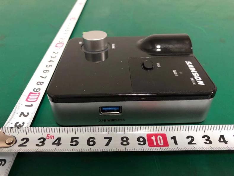
CCRRXD1M
Mar 18, 20202.4G Wireless microphone Receiver
Equipment Class
DXX - Part 15 Low Power Communication Device Transmitter