CCRR600Wireless Ear Monitor
Sam Ash Music Corporation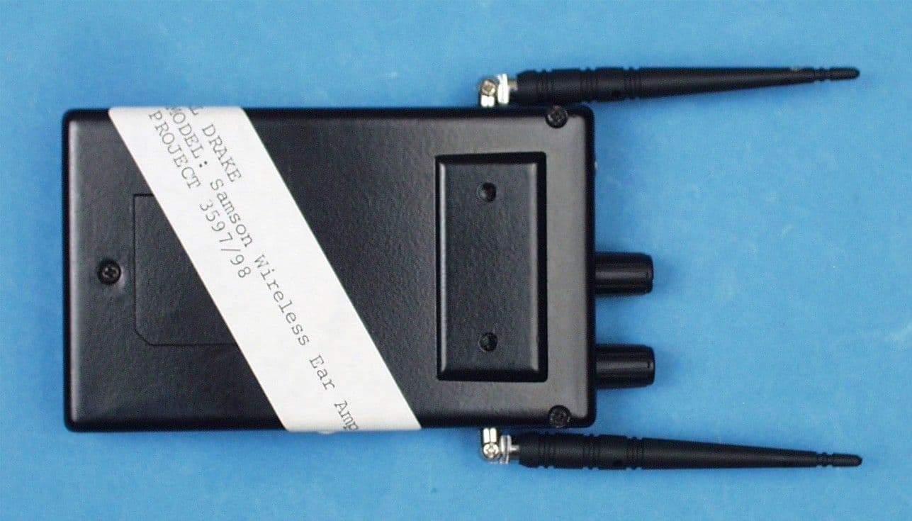
Click to zoom
Application Details
- Equipment Class
- CYY - Communications Receiver used w/Pt 15 Transmitter
- Date of Grant
- Jul 27, 2000
- Application Purpose
- Original Equipment
- Date of Application
- Jul 27, 2000
- Equipment Note
- Wireless Ear Monitor
- Frequency Range
- 614.00000000 - 662.00000000
- Company
- Sam Ash Music Corporation
- Country
- United States
Documents & Files
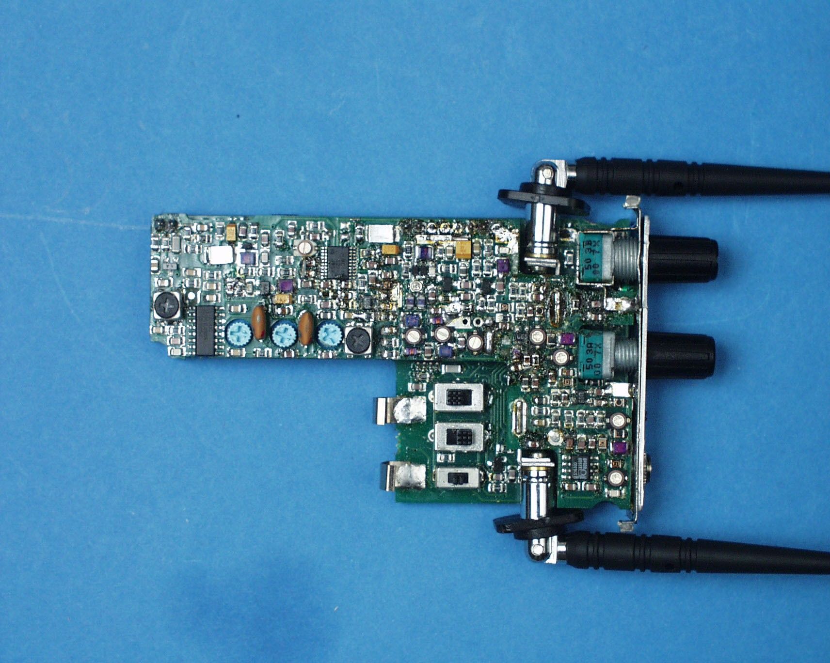
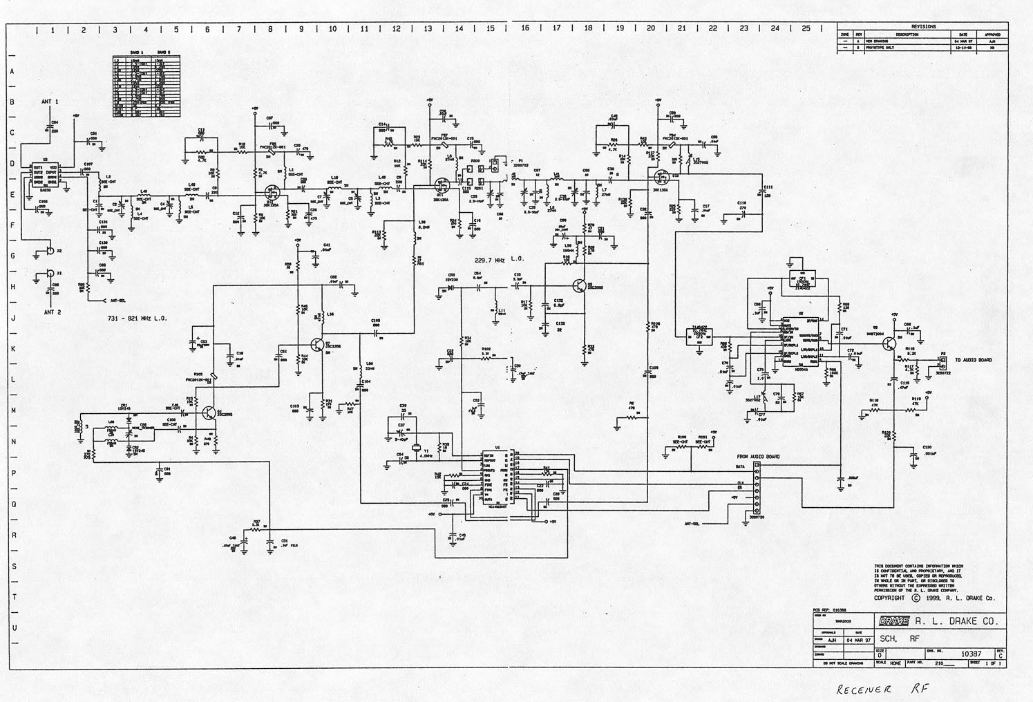
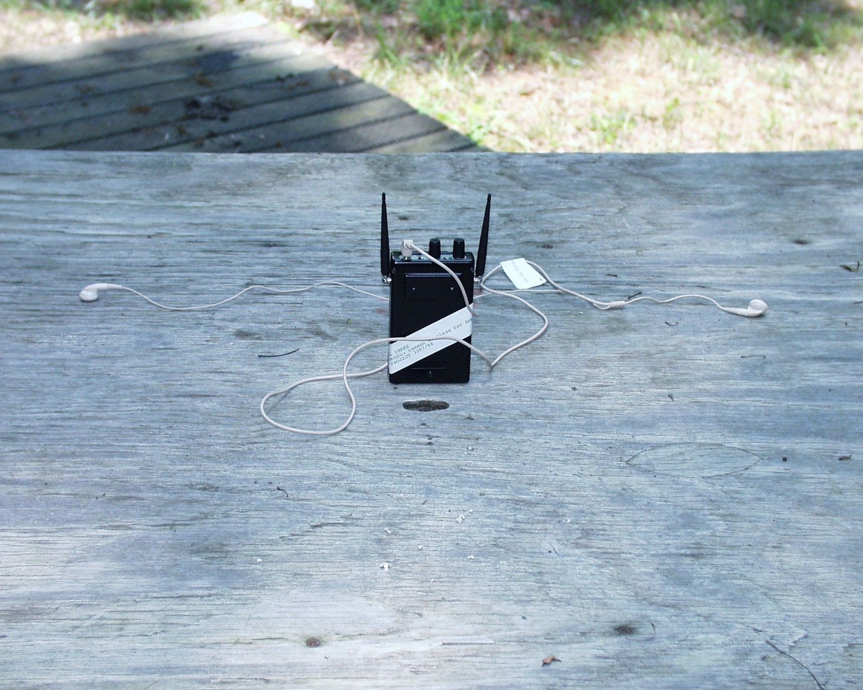
Document Text
Text extracted from the exhibit documents filed with the FCC. Open a document above to read the original.
Test Report
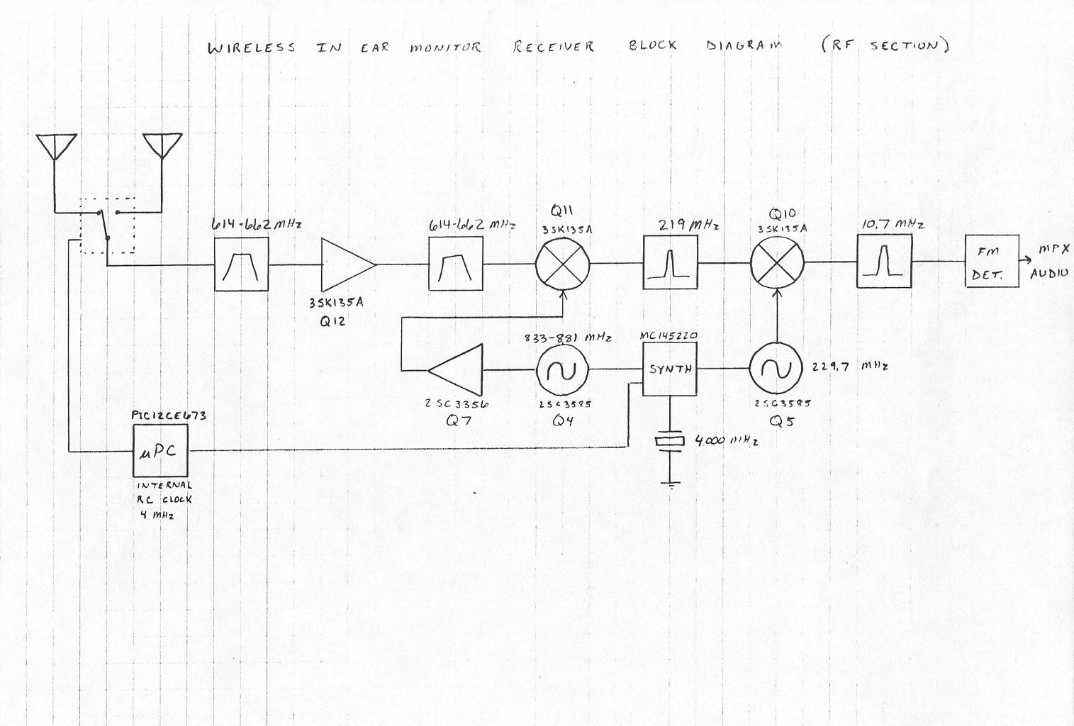
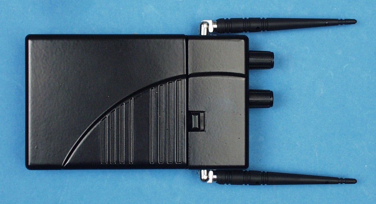
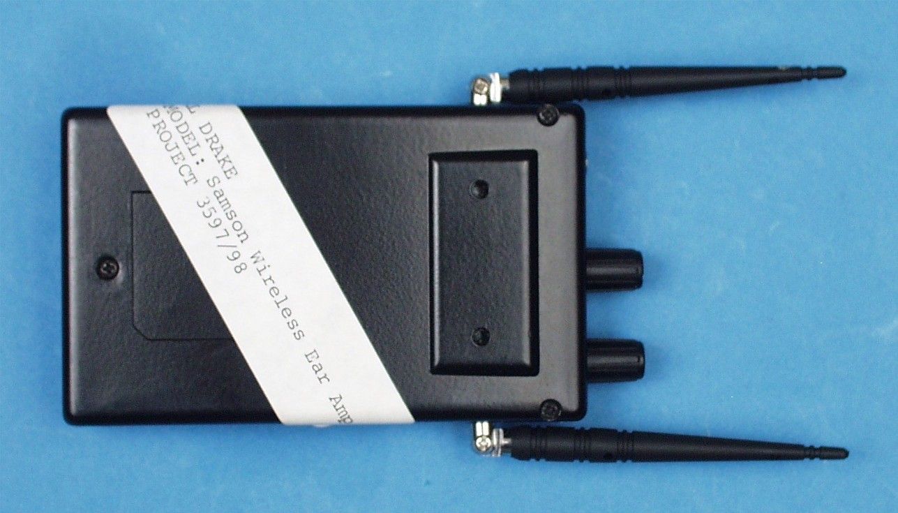
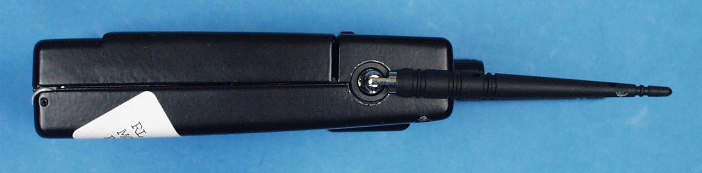
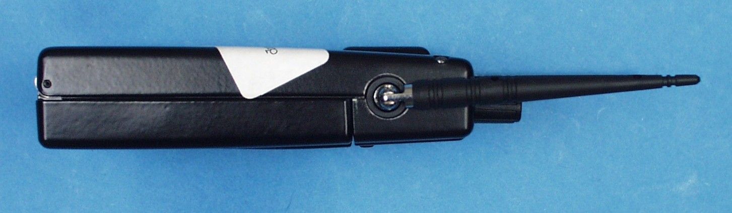
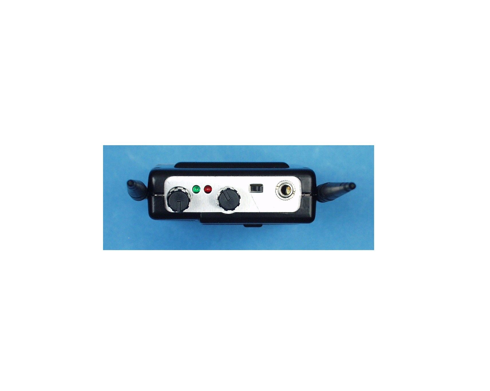
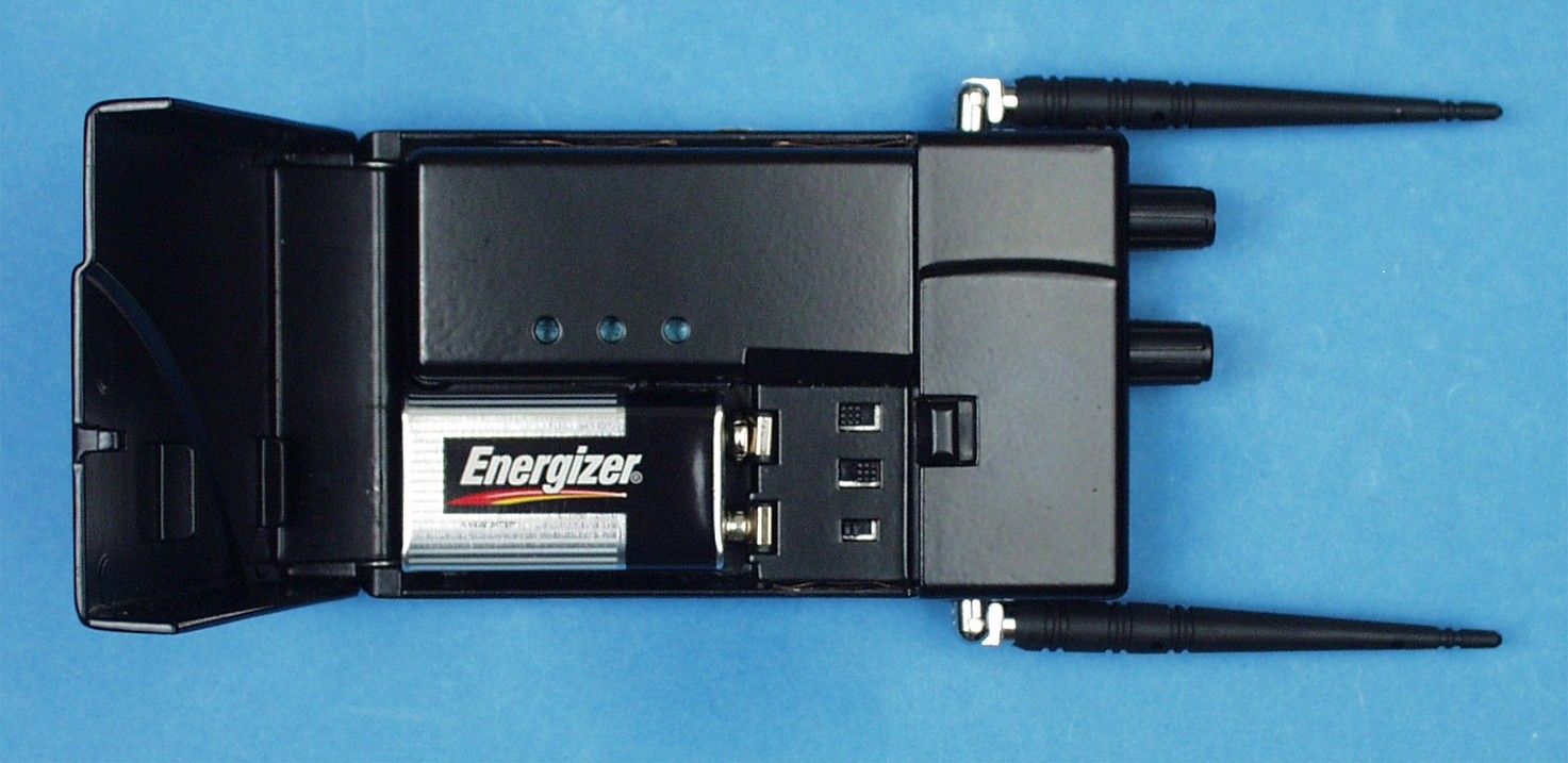
ENGINEERING STATEMENT In Regard to Measurements on SAM ASH MUSIC CORPORATION MODEL: Ear Amp R600 FCC ID: CCRR600 A. INTRODUCTION Hyak Laboratories, Inc. has been authorized by Sam Ash Music Corporation to perform measurements on a receiver to determine compliance with FCC rules, Part 15, Subpart B. The receiver operates in the 614 - 662 MHz band and is intended for use as a wireless ear monitor. B. DESCRIPTION OF RECEIVER The receiver incorporates a dual-diversity, dual conver- sion, super-heterodyne design. The following information is supplied as requested in FCC Bulletin OCE 24: 1. Service in which the receiver will be used: Part 15. (74). 2. Function of receiver: Wireless Monitor. 3. Tuning range: 614 - 662 MHz. 4. IF used: 219 MHz; 10.7 MHz. 5. Fundamental frequency of principal oscillators in the receiver. First local oscillator: (F o -219) MHz. C. DESCRIPTION OF MEASUREMENT FACILITIES A description of the Hyak Laboratories' radiation test faci- lity is a matter of record with the FCC. The facility was accepted for radiation measurements from 30 to 1000 MHz on October 1, 1976, and is currently listed as an accepted site. D. DESCRIPTION OF MEASUREMENT PROCEDURE: RADIATED EMISSIONS Measurements of receiver radiation field strength were made using ANSI C63.4 (1992) the basic procedure. Measurements were made with 3 meter spacing between the receiver under test and the test equipment antenna. The antennas connected to the receiver under test consisted of 2 vertically polarized, antenna approxi- mately 10 cm long. The receiver under test was placed on a rotatable table 80 cm in height. Measurement of field strength was made through use of a HP 8596E spectrum analyzer in conjunction with Singer DM-105A series calibrated dipoles, and Emco 3115 horn. For each spurious emission identified between 30 to 2000 MHz, the test sample was rotated for maximum pickup, the test antenna varied in elevation, and the test antenna polarization shifted between horizontal to vertical in order to maximize observed signals. E. REPORT OF RADIATED EMISSIONS Table 1 lists the frequency and amplitude of all signals observed from 30 to 2000 MHz that were within 20 dB of the limits of paragraph 15.109 of the FCC Rules for lower and upper operating channels. 2 TABLE 1 RADIATED SPURIOUS EMISSIONS Measured at 3 meters PART 15(B) PARA. 15.109 Frequency Frequency To Which of Meter Antenna Field 1 Tuned Emission Reading Factor Intensity FCC Limit dB to (MHz) (MHz) (dBm) (dB) uV/m @ 3m uV/m @ 3m Limit 615.000 833.992 -91.5 29.9 187 200 - 0.6 615.000 1667.982 -87.2 26.6 209 500 - 7.6 615.000 3335.960 -95.6 31.8 145 500 -10.8 615.000 4169.960 -99.2 33.4 115 500 -12.8 638.000 856.992 -92.1 29.9 175 200 - 1.2 638.000 1713.982 -88.4 26.8 186 500 - 8.6 638.000 2570.972 -91.6 29.8 182 500 - 8.8 638.000 3427.960 -94.0 32.1 180 500 - 9.0 661.000 879.992 -93.4 30.3 156 200 - 2.2 661.000 1759.982 -85.6 27.1 266 500 - 5.5 661.000 2639.970 -90.8 29.9 202 500 - 7.9 661.000 3519.960 -89.6 32.4 309 500 - 4.2 Note 1: uV/m = Log -1dBu/m 20 dBu = dBm + antenna factor + 107 *Reference data, 20 dB or more below FCC limit. RADIATED SPURIOUS EMISSIONS FCC ID: CCRR600 TABLE 1 3 F. PROCEDURE - AC LINE CONDUCTED SPURIOUS The receiver is battery powered, therefore no power line conducted spurious measurements were made. G. STATEMENT Technical test data are from tests performed by me or under my supervision. My qualifications are a matter of record with the Federal Communications Commission. I personally attest to the accuracy of the test data submitted as a part of this engineering statement. H. APPENDICES: The following appendices are submitted as separate exhibits: FCC ID Label and Location Photographs Schematic and Block Diagrams Owner’s Manual Test Set-Up Photo __________________________________ Rowland S. Johnson Dated: July 11, 2000 4
Contact Information
Applicant
Don Albanese
Test Firm
Hyak Laboratories, Inc.Rowland Johnson
703-451-1188
Technical Specifications
| # | Rule Parts | Frequency Range | Power Output |
|---|---|---|---|
| 1 | 15B | 614 MHz - 662 MHz | - |
Other Applications from Sam Ash Music Corporation
CCRCBXD2
Jan 11, 2024TRANSMITTER
Equipment Class
PUT - Part 15 Unlicensed PCS portable Tx worn on body
CCRCHXD2
Jan 11, 2024TRANSMITTER
Equipment Class
PUF - Part 15 Unlicensed PCS portable Tx held to face
CCRET100
Jan 09, 2024ET100 UHF Transmitter
Equipment Class
TLD - Licensed LPAS Device
CCRXP106W
May 20, 2020Bluetooth Speaker
Equipment Class
DSS - Part 15 Spread Spectrum Transmitter
CCRRXD1M
Mar 18, 20202.4G Wireless microphone Receiver
Equipment Class
DXX - Part 15 Low Power Communication Device Transmitter