CCRT600UHF Earamp Transmitter
Sam Ash Music Corporation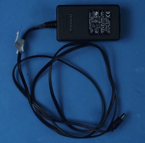
Click to zoom
Application Details
- Equipment Class
- TBC - Licensed Broadcast Station Transmitter
- Date of Grant
- Sep 12, 2000
- Application Purpose
- Original Equipment
- Date of Application
- Oct 30, 2000
- Equipment Note
- UHF Earamp Transmitter
- Frequency Range
- 614.00000000 - 662.00000000
- Company
- Sam Ash Music Corporation
- Country
- United States
Documents & Files
Document Text
Text extracted from the exhibit documents filed with the FCC. Open a document above to read the original.
External Photos
Front View Top View Back View Botto m View AC Adapter
ID Label/Location Info
FCC ID: CCRT600
Operational Description
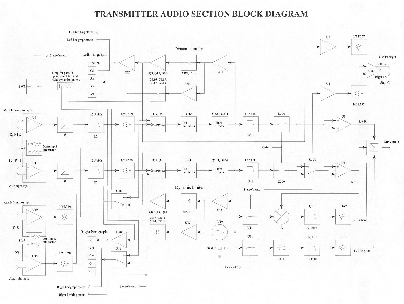
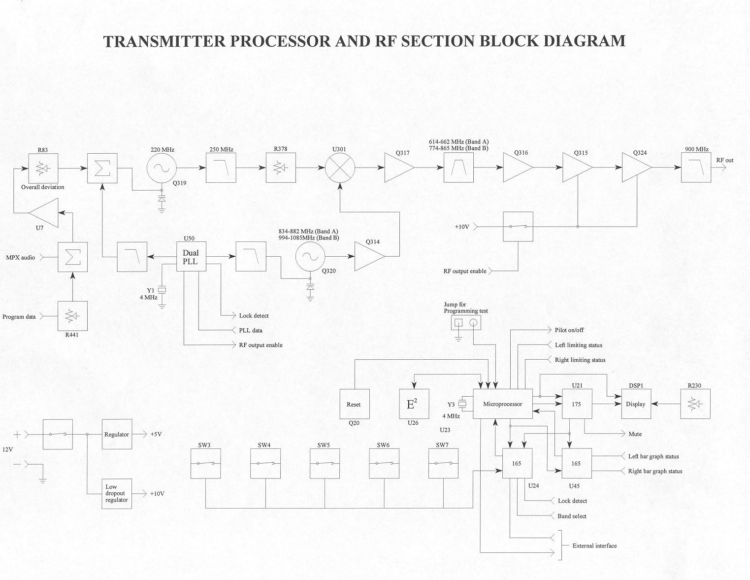
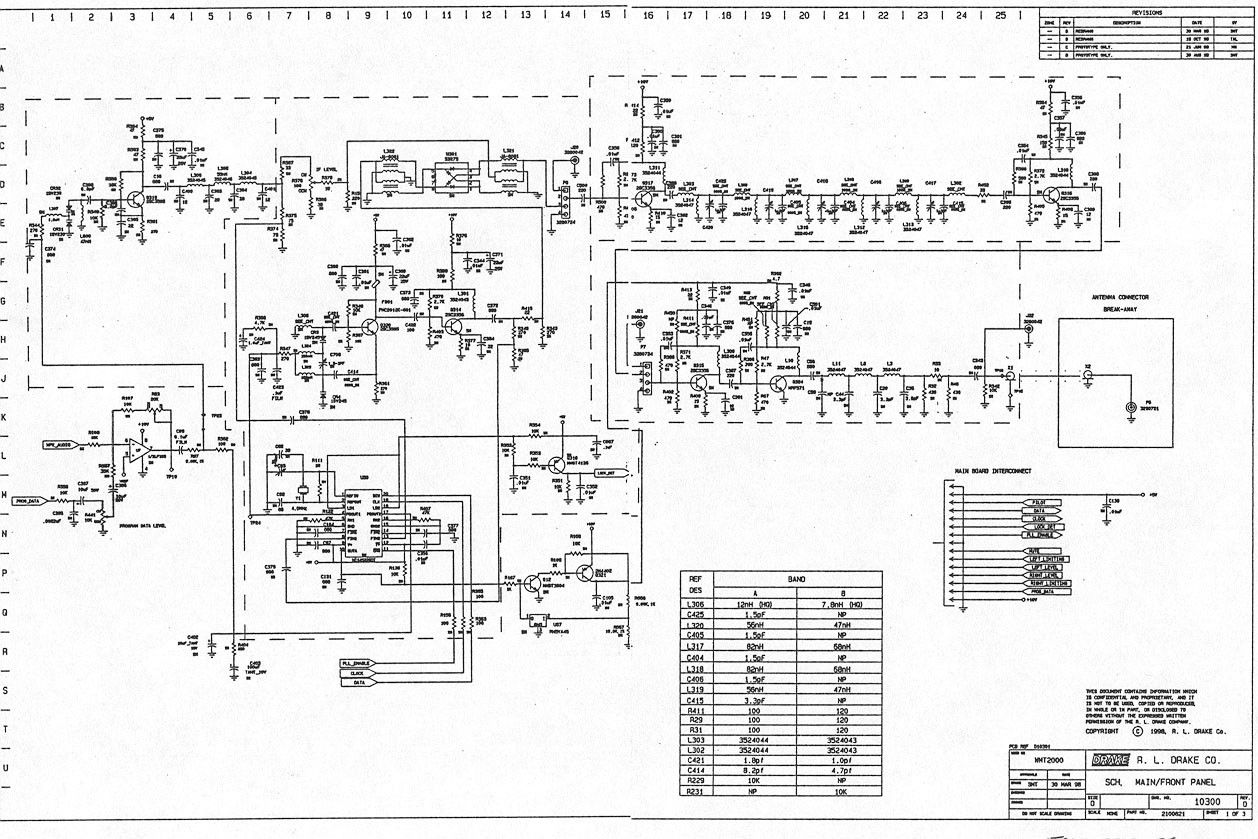
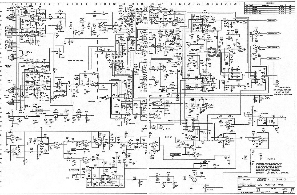
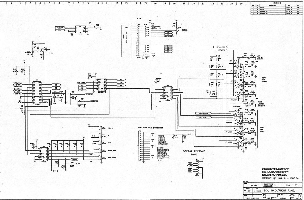
Description of Circuits to Suppress Emissions A fixed frequency L.O. operating on 220 MHz is mixed up to the desired output frequency by a doubly balanced mixer made up of L322, U301, and L321. The 220 MHz signal is passed through a low pass filter before being applied to the mixer to prevent any harmonics from leading to any undesired products that could lie within the pass band. The pass band for the U.S. version (Band A) is 614-662 MHz and for the export version (Band B) it is 774-865 N4hz. The 21 L.O. operates 220 MHz above the output frequency. The output of the mixer is amplified by Q317, then fed through a pass band filter which is tuned to pass only the low side product of the conversion. Any undesired products are to be greater than 60 dBc below the desired signal at this point. The desired signal is then fed to an amplifier chain composed of Q316, Q315, and Q324. After amplification, the signal is passed through a low pass filter to remove any harmonics generated by the amplifiers. In addition, the processor monitors the PLL for an out of lock condition of either synthesizer. The processor, with the aid of Q12 and Q321, provides power for the last two stages of final amplification only if both loops have been locked for a predetermined amount of time. This reduces the possibility of transmitting off frequency and also prevents transmitting upon power up while the synthesizers acquire lock. Description of Circuits to Limit Modulation Each channel is limited independently by both a hard limiter and a dynamic limiter. The dynamic limiter functions as an AGC once full modulation is reached. If additional audio is applied, the limiter will reduce the gain of the audio path by overriding the compressor. This maintains legal modulation with little if any noticeable distortion. There is an optional jumper that will cause both limiters to be activated whenever either one is triggered. This feature is designed to maintain a specific balance between the two channels regardless of which channel has excessive audio apllied. Since each dynamic limiter is designed to ignore transients, the hard limiters are present only to limit anything the dynamic limiters allow to pass. Audio is fed through the compressor (U5), then pre-emphasized by U40(left channel) or U41 (right channel). Q200 and Q20 I (left channel) or Q203 and Q204 (right channel) provide the hard limiting. At this point the audio is amplified byUI4 (left channel) or UI3(right channel) and rectified by CR7 and CR8(left channel) or CR5 and CR6(right channel). The resulting DC voltage is applied to a comparator formed by Q9, Ql 5, and Ql 6(left channel) or Q8, Ql 3, and Q 14(right channel). Once a preset voltage is exceeded at the input of the comparator, the output of the comparator overrides the feedback loop in the compressor and reduces the audio path gain as needed to maintain legal modulation. The top bar graph LED indicates whenever any dynamic limiting is being employed.
Test Report
ENGINEERING STATEMENT For Type Certification of SAM ASH MUSIC CORPORATION Model: Ear Amp T600 FCC ID: CRRT600 I am an Electronics Engineer, a principal in the firm of Hyak Laboratories, Inc., Springfield, Virginia. My education and experience are a matter of record with the Federal Communications Commission. Hyak Laboratories, Inc. has been retained by Sam Ash Music Corporation to make type certification measurements on the T600 transmitter. These tests made by me or under my supervision in our Springfield laboratory. Test data required by the FCC for type certification are included in this report. It is submitted that the above mentioned transmitter meets FCC requirements and type certification is requested. ______________________________ Rowland S. Johnson Dated: August 28, 2000 A. INTRODUCTION The following data are submitted in connection with this request for type certification of the T600 transmitter in accordance with Part 2, Subpart J of the FCC Rules. The T600 is a 50 milliwatt, UHF, frequency modulated, synthesized, ac-line operated transmitter configured as a rack- mount chassis for wireless ear monitor applications under Part 74. B. GENERAL INFORMATION REQUIRED FOR TYPE CERTIFICATION (Paragraph 2.983 of the Rules) 1. Name of applicant: Sam Ash Music Corporation 2. Identification of equipment: FCC ID: CRRT600 a. The equipment identification label is included as a separate exhibit. b. Photographs of the equipment are included as a separate exhibit. 3. Quantity production is planned. 4. Technical description: a. Emission 87k0F3E b. Frequency range: 614 - 662 MHz. c. Operating power of transmitter is fixed at the factory at 50 mW. d. Maximum power permitted under Part 74.861(e) (1)(ii) of the rules is 250 milliwatts, and the T600 complied with those power limitations. e. Function of each active semiconductor device: See Appendix 1. f. Complete circuit diagram is included as a separate exhibit. g. A draft instruction book is included as a separate exhibit. h. The transmitter tune-up procedure is included as a separate exhibit. 2 B. GENERAL INFORMATION REQUIRED (Continued) i. A description of circuits for stabilizing frequency is included in Appendix 2. j. A description of circuits and devices employed for suppression of spurious radiation and for limiting modulation is included in Appendix 3. k. Not applicable. 5. Data for 2.985 through 2.997 follow this section. 6. RF_Power_Output (Paragraph 2.987(a) of the Rules) The device has a BNC RF output connector. RF output power, was measured using an HP 432 power meter as 54 mW. NOTE: All audio measurements were made hard-wired using the normal input connector. C. MODULATION CHARACTERISTICS 1. A curve showing frequency response of the transmitter is shown in Figure 1. Reference level was a 1 kHz au- dio signal at 10 kHz deviation. A Boonton 8220 modula- tion meter was used to measure deviation. Audio output was measured from an Audio Precision System One integrated measurement system. 2. Under Section 74.861 no modulation limiting is required. 3. Occupied_Bandwidth (Paragraphs 2.989(c), and 74.861(6) of the Rules) Figure 2 is a plot of the sideband envelope of the transmitter taken with a Tektronix 494P spectrum analyzer. Modulation consisted of a 14.5 kHz tone, the frequency of maximum response, at an input level 16 dB greater than that necessary to produce 50% modulation. NOTE: Audio bandwidth is 15 kHz, and maximum system deviation (0dBm input) is 29 kHz. Using 2D+2F = modulation factor. Where "D" is rated system deviation, and "F" is maximum modulation frequency, an emission designator of 87k0F3E was computed. 3 FIGURE 1 MODULATION FREQUENCY RESPONSE MODULATION FREQUENCY RESPONSE FCC ID: CRRT600 FIGURE 1 4 FIGURE 2 OCCUPIED BANDWIDTH OCCUPIED BANDWIDTH FCC ID: CRRT600 FIGURE 2 5 C. MODULATION CHARACTERISTICS (Continued) The plots are within the limits imposed by paragraph 74.861(6). The horizontal scale (frequency is 50 kHz per division) and the vertical scale (amplitude) is a logarithmic presentation equal to 10 dB per division. D. SPURIOUS EMISSIONS AT THE ANTENNA TERMINALS (Paragraph 2.991 of the Rules) The T600 transmitter was tested for spurious emissions at the antenna terminals while the equipment was modulated with a 15 kHz signal, 16 dB above minimum input signal for 50% modulation. Measurements were made with Tektronix 494P spectrum analyzer coupled to the transmitter output terminal through a Narda 765-20 power attenuator. A notch filter was used to attenuate the carrier. During the tests, the transmitter was terminated in the 50 ohm attenuator. Power was monitored on a Bird 43 Thru-Line wattmeter; ac supply was 117 volts throughout the tests. Spurious emissions were measured throughout the RF spectrum from lowest frequency generated in the transmitter to the tenth harmonic of the carrier. Any emissions that were between the required attenuation and the noise floor of the spectrum analyzer were recorded. Data are shown in Table 1. E. DESCRIPTION OF RADIATED SPURIOUS MEASUREMENT FACILITIES A description of the Hyak Laboratories’ radiation test facility is a matter of record with the FCC. The facility meets ANSI 63.4-1992 and was accepted for radiation measurements from 25 to 1000 MHz on October 1, 1976 and is currently listed as an accepted site. 6 TABLE 1 TRANSMITTER CONDUCTED SPURIOUS 635.8, 117 Vac, 53.7 mW Spurious dB Below Frequency Carrier ___MHz___ Reference 1271.602 81 1907.402 96 2543.208 >100 3179.010 >100 3814.812 >100 4450.614 >100 5086.416 >100 5722.218 >100 6358.020 >100 6993.822 100 Required: 43+10Log(P) 30 All other emissions from 12 MHz to the tenth harmonic were 20 dB or more below FCC limit. NOTE: Carrier notch filter used to increase dynamic range. 7 F. FIELD STRENGTH MEASUREMENTS OF SPURIOUS RADIATION Field intensity measurements of radiated spurious emissions from the T600 were made with a Tektronix 494P spectrum analyzer using Singer DM-105A calibrated dipole antennas below 1 GHz, and Polarad CA-L, a…
Text truncated - open the document above for the full version.
Test Report
E. FIELD STRENGTH MEASUREMENTS The tabulated data shows the results of the radiated field strength measured by the substitution method. The spectrum was scanned from 30MHz to 6.3305GHz. This test was done per TIA/EIA 603 Paragraph 2.2.12. TABLE 2B TRANSMITTER CABINET RADIATED SPURIOUS 633.05 MHz, 117 Vac, 53.7 mW Spurious dB Below Frequency Carrier ___MHz__ Reference 1 633.05 0.0 1266.102 -85.4 1899.156 -87.6 2532.208 -89.4 3165.260 <-92.4 Required: 43+10Log(P) 30 1 Worst-case polarization, H-Horizontal, V-Vertical. *Reference data only, more than 20 dB below FCC limit. All other spurious to 7.0 GHz were 20 dB or more below FCC limit.
Contact Information
Applicant
Don Albanese
Test Firm
Hyak Laboratories, Inc.Rowland Johnson
703-451-1188
Technical Specifications
| # | Rule Parts | Frequency Range | Power Output | Emission | Tolerance |
|---|---|---|---|---|---|
| 1 | 74 | 614 MHz - 662 MHz | 54.00 mW | 87K0F3E | 0.0050000000 % |
Other Applications from Sam Ash Music Corporation
CCRCBXD2
Jan 11, 2024TRANSMITTER
Equipment Class
PUT - Part 15 Unlicensed PCS portable Tx worn on body
CCRCHXD2
Jan 11, 2024TRANSMITTER
Equipment Class
PUF - Part 15 Unlicensed PCS portable Tx held to face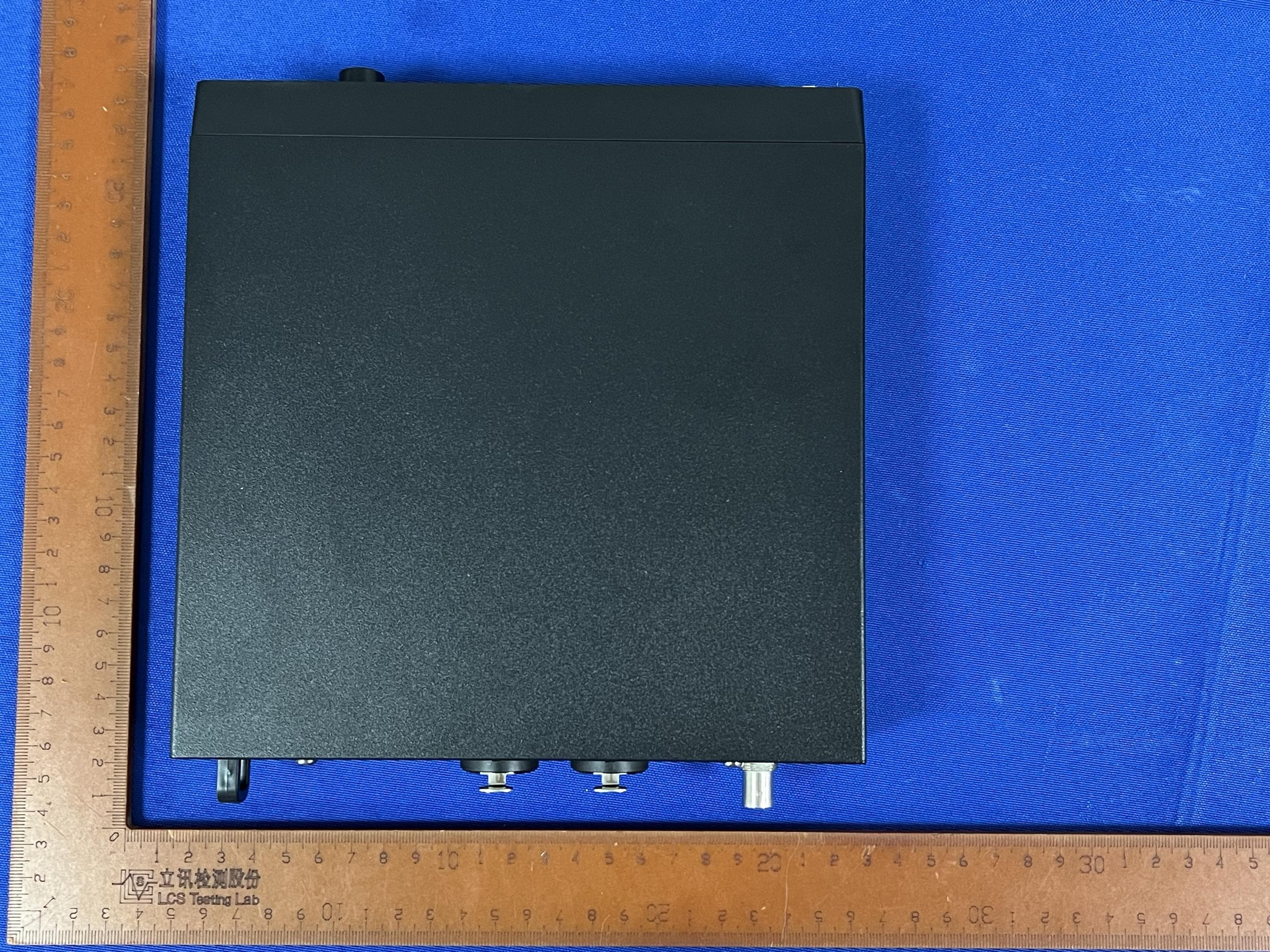
CCRET100
Jan 09, 2024ET100 UHF Transmitter
Equipment Class
TLD - Licensed LPAS Device
CCRXP106W
May 20, 2020Bluetooth Speaker
Equipment Class
DSS - Part 15 Spread Spectrum Transmitter
CCRRXD1M
Mar 18, 20202.4G Wireless microphone Receiver
Equipment Class
DXX - Part 15 Low Power Communication Device Transmitter