CGDLD4KW4kW Electronic Lamp Driver
Nedap N. V.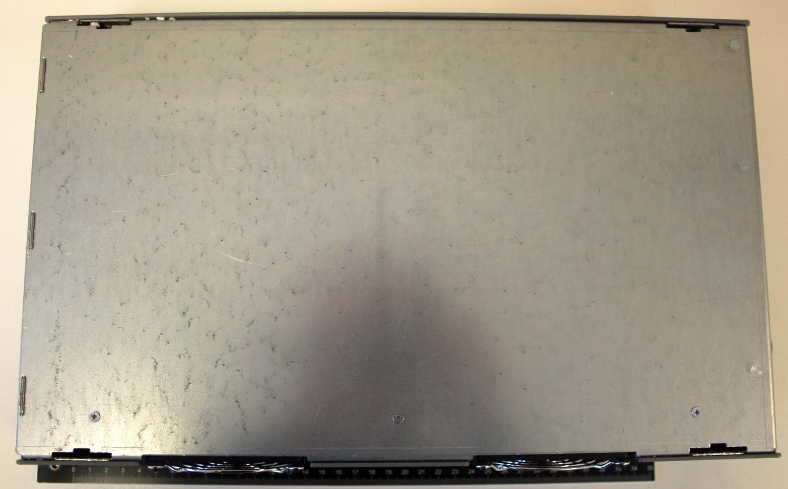
Click to zoom
Application Details
- Equipment Class
- DTS - Digital Transmission System
- Date of Grant
- Jul 15, 2020
- Application Purpose
- Original Equipment
- Date of Application
- Jul 15, 2020
- Equipment Note
- 4kW Electronic Lamp Driver
- Frequency Range
- 2402.00000000 - 2480.00000000
- Company
- Nedap N. V.
- Country
- Netherlands
Documents & Files
Document Text
Text extracted from the exhibit documents filed with the FCC. Open a document above to read the original.
Users Manual
Copyright © by NEDAP Light Controls Page 1 of 17 4kW Electronic Lamp Driver Nedap Light Controls PO Box 101 NL-7140 AC Groenlo Netherlands www.nedap-uv.com [email protected] ��+31(0)544.471111 Copyright © by N.V. Nederlandse Apparatenfabriek - NEDAP -. No part of this drawing may be reproduced or distributed in any form or by any means, or stored in a database or retrieval system, without the prior written permission of NEDAP. Products : Lamp driver 4kW + Housing 9987126 Date Rev. : June 30, 2020 1.2 4kW Lamp Driver - Manual Copyright © by NEDAP Light Controls Page 2 of 17 Table of Contents: 1. Introduction .................................................................................................................................................................. 3 1.1. Description ............................................................................................................................................................. 3 1.2. Usage ..................................................................................................................................................................... 3 2. Safety ............................................................................................................................................................................ 3 3. Installation .................................................................................................................................................................... 4 3.1. Mounting the lamp driver ........................................................................................................................................ 4 3.2. Output connections ................................................................................................................................................. 4 3.2.1. Connect lamp wiring : Lamp output ................................................................................................................. 4 3.2.2. Lamp output Voltage ranges ............................................................................................................................ 5 3.3. Input connections .................................................................................................................................................... 5 3.3.1. Input wiring connection: AC input, Ground ..................................................................................................... 5 3.3.2. AC input voltage range .................................................................................................................................... 5 3.4. Control connections ................................................................................................................................................ 6 3.4.1. Connect control wiring : Can & Sync Input ...................................................................................................... 6 3.4.2. Connect control wiring : Can & Sync Output ................................................................................................... 6 3.4.3. Baud rate setting.............................................................................................................................................. 6 3.4.4. Connect control wiring : Modbus Input ............................................................................................................ 6 3.4.5. Modbus Input connector .................................................................................................................................. 6 3.4.6. Connect control wiring : Modbus Output ......................................................................................................... 7 3.4.7. Modbus Output connector ............................................................................................................................... 7 3.4.8. BCD Rotary Switches...................................................................................................................................... 7 3.4.9. Status LEDs .................................................................................................................................................... 7 3.5. External breaker ..................................................................................................................................................... 8 4. Control of Lamp Driver ............................................................................................................................................... 8 4.1. Switching lamp on/off ............................................................................................................................................. 8 4.2. Dimming lamp ........................................................................................................................................................ 8 4.3. Status Relay : Lamp PWR Ok signal ........................................................................................................................ 9 4.4. Error signals ........................................................................................................................................................ 10 4.4.1. Lamp Error ................................................................................................................................................... 10 4.4.2. System Error ................................................................................................................................................. 10 4.4.3. Lamp Driver Error......................................................................................................................................... 10 5. Service......................................................................................................................................................................... 11 5.1. Fan .........…
Text truncated - open the document above for the full version.
Cover Letter(s)
Page: 1/1 of «DocRef» dated 02-07-2020 ® TÜV, TUEV a nd TUV are registered trademarks. Any use or application requires prior approval. To whom it may concern, On behalf of our customer Nedap N.V. we hereby would like to apply for an Original certification for the following device: FCC ID : CGDLD4KW IC : 1444A-LD4KW Manufacturer : Nedap N.V. Brand : Nedap Model : LAMP DRIVER 4KW Description : Digital Transmission System (DTS) The following PDF files (exhibits) are electronically submitted: 1. Cover letter (this document) 2. Request or confidentiality 3. Authorization letter 4. Form 731 5. Antenna information 6. Bill of material (BOM)- Not required-Not provided 7. Block diagram 8. Circuit diagram 9. Interior photographs 10. Exterior photographs 11. Label information 12. Operational description 13. Test report in conformity with 47 CFR Part 15 / RSS-Gen 14. Test setup photographs 15. User/installation manual 16. RF Exposure Best regards, TÜV Rheinland Nederland B.V. R .van der Meer Test Engineer TÜV Rheinland Nederland B.V. Eiberkamp 10 9351VT Leek The Netherlands Telephone: +31 888887888 Internet: www.tuv.com/nl E-mail: [email protected]
Cover Letter(s)
Trade register: 08013836 | IBAN: NL08 ABNA 0453299555 | BIC: ANBNANL2A | VAT: NL006456285B01 The General Terms and Conditions of ICT-Office apply to all our offers and agreements. These conditions can be found at our website and can be provided upon request. July 03, 2020 Subject: Confidentiality Request for FCC ID: _CGDLD4KW and IC: 1444A-LD4KW Pursuant to FCC 47 CRF 0.457(d) and 0.459 and IC RSP-100, Section 10, the applicant requests that a part of the subject FCC/IC application be held confidential. Type of Confidentiality Requested Exhibit Short Term Permanent Block Diagrams Short Term Permanent Operation Description/Theory of Operation Short Term Permanent Schematics Nedap N. V. has spent substantial effort in developing this product and it is one of the first of its kind in industry. Having the subject information easily available to "competition" would negate the advantage they have achieved by developing this product. Not protecting the details of the design will result in financial hardship. Permanent Confidentiality: The applicant requests the exhibits listed above as permanently confidential be permanently withheld from public review due to materials that contain trade secrets and proprietary information not customarily released to the public. Short-Term Confidentiality: The applicant requests the exhibits selected above as short term confidential be withheld from public view for a period of 180 days from the date of the Grant of Equipment Authorization and prior to marketing. This is to avoid premature release of sensitive information prior to marketing or release of the product to the public. Applicant is also aware that they are responsible to notify TUV Rheinland in the event information regarding the product or the product is made available to the public. TUV Rheinland will then release the documents listed above for public disclosure pursuant to FCC Public Notice DA 04-1705. Sincerely, By: _____________/ Compliance manager_ _Reinold Hubers_ (Signature/Title) (Print name) Nedap N.V. Parallelweg 2 7141 DC Groenlo The Netherlands T: +31 (0)544 471 111 [email protected] www.nedap.com
External Photos
Testing and certification of electronic and electric appliances, systems, installations and telecommunication systems TÜV Rheinland Nederland B.V. Eiberkamp 10 9351VT Leek The Netherlands Telephone: +31 888887888 Internet: www.tuv.com/nl E-mail: [email protected] Project number: 19111401A.p02 Page 1 of 6 PHOTOGRAPHS OF THE EXTERIOR OF A BRAND NEDAP, MODEL LAMP DRIVER 4KW Brand mark: Model: Nedap Project number: 19111401A.p02 Page 2 of 6 Table of contents 1 PHOTOGRAPHS OF THE EQUIPMENT. ............................................................................................................. 3 1.1 EXTERNAL VIEW. ............................................................................................................................................... 3 1.1.1 Top view. ................................................................................................................................................. 3 1.1.2 Bottom view. ............................................................................................................................................ 4 1.1.3 Front view. ............................................................................................................................................... 5 1.1.4 Rear view ................................................................................................................................................ 5 1.2 SIDE VIEWS ...................................................................................................................................................... 6 Brand mark: Model: Nedap Project number: 19111401A.p02 Page 3 of 6 1 Photographs of the equipment. 1.1 External view. 1.1.1 Top view. Brand mark: Model: Nedap Project number: 19111401A.p02 Page 4 of 6 1.1.2 Bottom view. Brand mark: Model: Nedap Project number: 19111401A.p02 Page 5 of 6 1.1.3 Front view. 1.1.4 Rear view Brand mark: Model: Nedap Project number: 19111401A.p02 Page 6 of 6 1.2 Side views Left side view Right side view END OF REPORT
ID Label/Location Info
Label info Location of the label on the back side of the device
Internal Photos
Testing and certification of electronic and electric appliances, systems, installations and telecommunication systems TÜV Rheinland Nederland B.V. Eiberkamp 10 9351VT Leek The Netherlands Telephone: +31888887888 Internet: www.tuv.com/nl E-mail: [email protected] Project number: 19111401A.p01 Page 1 of 8 PHOTOGRAPHS OF THE INTERIOR OF A BRAND NEDAP, MODEL LAMP DRIVER 4KW Brand mark: Model: Nedap Project number: 19111401A.p01 Page 2 of 8 Table of contents 1.1 INTERNAL VIEW 1, TOP COVER REMOVED. ........................................................................................................... 3 1.2 INTERNAL VIEW 2, PCB ASSEMBLY AS INSTALLED IN THE UNIT ............................................................................. 4 .................................................................................................................................................................................. 4 1.3 INTERNAL VIEW 2, PCB MAIN BOARD ................................................................................................................. 5 2 INNER ASSEMBLY, PCB VIEW .......................................................................................................................... 6 2.1 MAIN PCB VIEW, COMPONENT SIDE. .................................................................................................................. 6 2.2 RF PCB VIEW, BACK SIDE ................................................................................................................................. 7 2.3 PCB VIEW – ANTENNA DETAIL ........................................................................................................................... 8 Brand mark: Model: Nedap Project number: 19111401A.p01 Page 3 of 8 1.1 Internal view 1, top cover removed. Brand mark: Model: Nedap Project number: 19111401A.p01 Page 4 of 8 1.2 Internal view 2, PCB assembly as installed in the unit Brand mark: Model: Nedap Project number: 19111401A.p01 Page 5 of 8 1.3 Internal view 2, PCB Main board Brand mark: Model: Nedap Project number: 19111401A.p01 Page 6 of 8 2 Inner assembly, PCB view 2.1 Main PCB view, component side. Brand mark: Model: Nedap Project number: 19111401A.p01 Page 7 of 8 2.2 RF PCB view, back side Brand mark: Model: Nedap Project number: 19111401A.p01 Page 8 of 8 2.3 PCB view – Antenna detail END OF REPORT
Test Report
FCC ID: CGDLD4KW IC: 1444A-LD4KW Page 1 of 49 Prüfbericht-Nr.: Test Report No.: 19111401A.r01 Auftrags-Nr.: Order No.: 89003529 Seite 1 von 49 Page 1 of 49 Kunden-Referenz-Nr.: Client Reference No.: 1659792 Auftragsdatum: Order date: 23.03.2020 Auftraggeber: Client: Nedap N.V. Prüfgegenstand: Test item: Digital Transmission System (DTS) Lamp driver 4kW, Radio interface Bezeichnung / Typ-Nr.: Identification / Type No.: Lamp driver 4kW Auftrags-Inhalt: Order content: Compliance with standard Prüfgrundlage: Test specification: FCC 47 CFR Part 15, Subpart C, Section 15.247 (10-1-19 Edition) RSS-Gen (Issue 5, March 2019) and RSS-247 (Issue 2, February 2017) ANSI C63.10-2013 KDB 558074 D0115.247 Meas Guidance v05r02, April 2, 2019 Wareneingangsdatum: Date of receipt: 23.04.2020 Prüfmuster-Nr.: Test sample No.: Sample 1 (radiated tests) Sample 3 (conducted tests) Prüfzeitraum: Testing period: 28.04.2020 – 13.05.2020 Ort der Prüfung: Place of testing: Leek Prüflaboratorium: Testing laboratory: TÜV Rheinland Nederland B.V. Leek Laboratory Prüfergebnis*: Test result*: PASS geprüft von / tested by: Kontrolliert von / reviewed & approved by: 8-Jun-20 Richard van der Meer/ Test Engineer 8-Jun-20 Erik van der Wal, Senior Expert Telecom Datum Date Name / Stellung Name / Position Unterschrift Signature Datum Date Name / Stellung Name / Position Unterschrift Signature Sonstiges / Other: report issue date is equal to approved date. Zustand des Prüfgegenstandes be Anlieferung: Condition of the test item at delivery:1 Prüfmuster vollständig und unbeschädigt Test item complete and undamaged * Legende: Legend: 1 = sehr gut P(ass) = entspricht o.g. 1 = very good P(ass) = passed a.m. 2 = gut Prüfgrundlage(n) 2 = good Test specification(s) 3 = befriedigend F(ail) = entspricht nicht o.g. Prüfgrundlage(n) 3 = satisfactory F(ail) a.m. test specification(s) 4 = ausreichend N/A = nicht anwendbar 4 = sufficient N/A = not applicable 5 = mangelhaft N/T/ = nicht getested 5 = poor N/T = not tested This test report only relates to the a.m. testsample. Without permission of the test center this test report is not permitted to be duplicated in extracts. This report does not entitle to carry any test mark. FCC ID: CGDLD4KW IC: 1444A-LD4KW Prüfbericht - Nr.: Test Report No.: 19111401A Seite 2 von 49 Page 2 of 49 TÜV Rheinland Nederland B.V. . Eiberkamp 10 . 9351 VT Leek . Tel: + 31 88 8887888 Mail: [email protected] . Web: www.tuv.com EUT front view EUT rear view FCC ID: CGDLD4KW IC: 1444A-LD4KW Test Report No.: 19111401A.r02 Page 3 of 49 TEST SUMMARY Test Specification Clause Test Case Pass Fail Not applicable Not performed §15.247(a2) Spectrum Bandwidth of a DTS System / 6dB BW § 15.247 (b) (3) Maximum output power (conducted) §15.247 (e) Peak power spectral density §15.247 (d) Band-edge compliance of conducted emissions §15.205 Band-edge compliance of radiated emissions §15.247 (d) Spurious Emission - conducted (Transmitter) § 15.209 Spurious Emission - radiated (Transmitter) § 15.207 AC Power Line Conducted Emissions <30 MHz Revisions Revisions Revision Revision Datum Date Anmerkung Remark Verfasser Author - 08.06.2020 First release R. van der Meer Note: Latest revision report will replace all previous reports FCC ID: CGDLD4KW IC: 1444A-LD4KW Test Report No.: 19111401A.r02 Page 4 of 49 Contents 1. GENERAL REMARKS ............................................................................................... 5 1.1.1 Complementary Materials ............................................................................................................ 5 1.1.2 Special Accessories ..................................................................................................................... 5 1.1.3 Equipment modifications .............................................................................................................. 5 2. TEST SITES ............................................................................................................ 6 2.1 TEST FACILITIES ..................................................................................................... 6 2.2 LIST OF TEST AND MEASUREMENT INSTRUMENTS TABLE 1: LIST OF TEST AND MEASUREMENT EQUIPMENT ..................................................................................... 7 2.3 MEASUREMENT UNCERTAINTY ................................................................................. 8 3. GENERAL PRODUCT INFORMATION ........................................................................... 9 3.1 COUNTERMEASURES TO ACHIEVE COMPLIANCE ......................................................... 9 3.2 OPERATION MODES ................................................................................................ 9 3.3 PHYSICAL CONFIGURATION FOR TESTING ............................................................... 10 3.4 TEST SOFTWARE .................................................................................................. 13 3.5 SPECIAL ACCESSORIES AND AUXILIARY EQUIPMENT ............................................... 13 4. TEST RESULTS ..................................................................................................... 14 4.1.1 DTS (6dB) and 99% Bandwidth ................................................................................................. 14 4.1.2 Conducted Output Power ........................................................................................................... 19 4.1.3 Peak Power Spectral Density .................................................................................................... 22 4.1.4 Band Edge Conducted Emissions ............................................................................................. 25 4.1.5 Radiated Spurious Emissions of Transmitter ............................................................................. 28 1.1.4 Plot of the emissions in the range 30 -1000 MHz ..................................................................... 30 1.1.5 Plots of…
Text truncated - open the document above for the full version.
Test Report
Produkte Products Prüfbericht-Nr.: Test Report No.: 19111401.f01 Auftrags-Nr.: Order No.: 89003296 Seite 1 von 24 Page 1 of 24 Kunden-Referenz-Nr.: Client Reference No.: 19KLC00467 Auftragsdatum: Order date: 04-12-2019 Auftraggeber: Client: Nedap NV Light Controls, Parallelweg 2, Groenlo, The Netherlands, 7141DC Prüfgegenstand: Test item: 4kW Lamp Driver Bezeichnung / Typ-Nr.: Identification / Type No.: 4kW Lamp Driver Auftrags-Inhalt: Order content: Testing EMC Prüfgrundlage: Test specification: - FCC 47 CFR Part 15B (US) INCL. ICES-003 (Canada) - FCC 47 CFR PART 18: (10-1-18 Edition) Wareneingangsdatum: Date of receipt: 06-12-2019 Prüfmuster-Nr.: Test sample No.: EMC Sample 2 Prüfzeitraum: Testing period: 06-12-2019 – 09-12-2019 Ort der Prüfung: Place of testing: Leek Prüflaboratorium: Testing laboratory: TÜV Rheinland Nederland B.V. Leek Laboratory Prüfergebnis*: Test result*: Pass Geprüft von / tested by: Kontrolliert von / reviewed by: 13-12-2019 W. Brouwer / EMC Test Engineer 13-01-2020 K.F. van der Molen / Senior Expert EMC Datum Date Name / Stellung Name / Position Unterschrift Signature Datum Date Name / Stellung Name / Position Unterschrift Signature Sonstiges / Other: None Zustand des Prüfgegenstandes be Anlieferung: 1 Condition of the test item at delivery: 1 Prüfmuster vollständig und unbeschädigt Test item complete and undamaged * Legende: Legend: 1 = sehr gut P(ass) = entspricht o.g. 1 = very good P(ass) = passed a.m. 2 = gut Prüfgrundlage(n) 2 = good Test specification(s) 3 = befriedigend F(ail) = entspricht nicht o.g. Prüfgrundlage(n) 3 = satisfactory F(ail) a.m. test specification(s) 4 = ausreichend N/A = nicht anwendbar 4 = sufficient N/A = not applicable 5 = mangelhaft N/T/ = nicht getested 5 = poor N/T = not tested Dieser Prüfbericht bezieht sich nur auf das o.g. Prüfmuster und darf ohne Genehmigung der Prüfstelle nicht auszugsweise vervielfältigt werden. Dieser Bericht berechtigt nicht zur Verwending eines Prüfzeichens. This test report only relates to the a.m. testsample. Without permission of the test center this test report is not permitted to be duplicated in extracts. This report does not entitle to carry any test mark EMC Test-report FCC 47 CFR Part 15B (US) INCL. ICES-003 (Canada) FCC 47 CFR PART 18 (US) V04 TÜV Rheinland Nederland B.V. . Eiberkamp 10 . 9351 VT Leek . Tel: + 31 88 8887888 Mail: [email protected] . Web: www.tuv.com Produkte Products Prufbericht-Nr: 19111401.f01 Test report No: 19111401.f01 Seite 2 von 24 Page 2 of 24 Rev.:01 Liste der verwendenten Prüfmittel List of used test equipment Conducted emission A00726 / 2789421 Rohde & Schwarz ESCS30 Measurement Receiver 1-11-2020 A01978 / 2790495 Rohde & Schwarz ESH3-Z2 Impulse Limiter 14-6-2020 A00051 / 2788823 Rohde & Schwarz ESH3-Z2 Impulse Limiter 23-9-2020 A01980 / 2790497 Rohde & Schwarz ESCS 30 Test Receiver. 17-7-2020 A00023 / 2788795 Emco 3625/2 LISN 5 uH / 50 ohm 23-9-2020 A00354 / 2789124 Rohde & Schwarz ESH2-Z5 LISN- artificial Network 19-8-2020 A00019 / 2788791 Rohde & Schwarz ESH2-Z5 LISN- artificial Network 30-6-2020 A00093 /2788866 COMTEST 1415 Conducted Reference Source 9kHz-50MHz 4-6-2020 A02011 / 2790528 Rohde & Schwarz ESH 3-Z5 LISN 23-9-2020 Radiated emission A00314 / 2789083 Rohde & Schwarz ESCI Measurement Receiver (9kHz-3GHz) 20-3-2020 A00337 / 2789106 R&S FSV30 Signal Analyzer/Spectrum Analyzer 1-8-2020 A00077 / 2788849 Chase CBL6111B Biconilog 29-10-2021 A00029 / 2788801 Emco 4610 Gen. field source 30-1-2020 A00235 / 2789009 Siepel FCC FCC Test Site Registration nr 786213 15-3-2020 A00313 / 2789082 Comtest Site registration filing Industry Canada 20-11-2020 A00436 / 2789206 Siepel S-AR 28-9-2020 A00447 / 2789217 Gigalink APG0500 RF Cable S-AR 4-3-2020 A00466 / 2789237 Teseq CBL 6111D Antenne S-AR, BiLog 30MHz-1GHz 6-11-2020 A01982 / 2790499 Rohde & Schwarz ESR7 EMI Test Receiver 7GHz 16-8-2020 A00008 / 2788776 Emco 3115 Guide ant. 1-18GHz 19-12-2020 A00009 / 2788777 Emco 3115 Guide ant. 1-18GHz 26-2-2022 A00011 / 2788779 Emco 3116 Guide ant. 18-40GHz 12-2-2022 A00012 / 2788780 Emco 3160-09 Gain horn 18-26.5GHz 12-2-2022 A00209 / 2788982 Emco 3160-09 Gain horn 18-26.5GHz 12-2-2022 A00210 / 2788983 Emco 3160-10 Gain horn 26.5-40GHz 12-2-2022 A00339 / 2789108 H&S Sucotest 18/Sucoflex 102 Cable RF S-AR >1G setup 23-7-2020 A00340 / 2789109 H&S Sucotest 18/Sucoflex 102 Cable RF 23-7-2020 A00341 / 2789110 H&S Sucotest 18/Sucoflex 102 Cable RF 23-7-2020 Prüfmittel Nr. / ID-Nr. Equipment No. / ID-No. Prüfmittel Test equipment Nächste Kalibrierung Next calibration Produkte Products Prufbericht-Nr: 19111401.f01 Test report No: 19111401.f01 Seite 3 von 24 Page 3 of 24 Rev.:01 1 Produktdetails Product details 4kW Lamp Driver 2 Bedienelemente Operating elements None 3 Ausstattung / Zubehör Equipment / Accessories Laptop, RS485/232 to USB converter, 4kW Load 4 Verwendete Materialien Used materials Cables 5 Sonstiges Other None 6 Dieser raport betrifft: This report concerns: EMC Verification Produkte Products Prufbericht-Nr: 19111401.f01 Test report No: 19111401.f01 Seite 4 von 24 Page 4 of 24 Rev.:01 Absatz Clause Anforderungen – Prüfungen / Requirements - Tests 1 47 CFR Part 15 (10-1-17 Edition) - 15.107(a) ICES-003 (Issue 6, January 2016) – Section 6.1 Table 2 And: 47 CFR Part 18 Subpart C - 18.307 AC Power Line Conducted Emissions (Lowest limits were used) P F N/A N/T 2 47 CFR Part 15 (10-1-17 Edition) - 15.109 ICES-003 (Issue 6, January 2016) – Section 6.2.1 Table 5 And: 47 CFR Part 18 Subpart C - 18.305 Radiated unwanted emissions (Lowest limits were used) P F N/A N/T Zusammenfassung der Prüfergebnisse Summary of test results Prüfung Test Anwendbar Applicable Prüfergebnis Test result Paragraf Paragraph Messungen un- ter Akkreditier- ung ausgeführt under accredita- tion Kommentar Remark Radiated emission < 1000 MHz Yes Pass 3.1 Yes Radiated emission > 1000 MHz Yes Pass 3.2 Yes Conducted emis- sion AC port Yes Pass 3.3 Yes Produkte Products Prufbericht-Nr: 19111401.f01 Test report No: 19…
Text truncated - open the document above for the full version.
Test Report
Testing and certification of electronic and electric appliances, systems, installations and telecommunication systems TÜV Rheinland Nederland B.V. Eiberkamp 10 9351VT Leek The Netherlands Telephone: +31 888887888 Internet: www.tuv.com/nl E-mail: [email protected] Project number: 19111401A.p03a Page 1 of 8 PHOTOGRAPHS OF THE TESTSETUP OF A BRAND Nedap, MODEL LAMP DRIVER 4KW Description of EUT: Manufacturer: Brand mark: Model: Digital Transmission System (DTS) Nedap N.V. Nedap Project number: 19111401a.p03a Page 2 of 8 Table of contents PHOTOGRAPHS OF THE TEST SETUP. .............................................................................................................................. 3 1.1 RADIATED EMISSIONS..................................................................................................................................................... 3 1.1.1 Radiated emissions setup below 1 GHz. ......................................................................................................... 3 1.1.2 Radiated emissions setup above 1 GHz, up to 18 GHz. ............................................................................... 4 1.1.3 Radiated emissions setup above 1 GHz, 18 G up to 25 GHz ....................................................................... 4 1.1.4 Radiated emissions setup detail, front and rear side. .................................................................................... 5 1.1.5 Radiated emissions setup detail, X,Y,Z orientations ...................................................................................... 6 1.2 ANTENNA PORT CONDUCTED TESTS ............................................................................................................................ 7 1.2.1 Conducted tests test setup overview ................................................................................................................ 7 2 AC POWER LINE CONDUCTED EMISSIONS TEST SETUP..................................................................................... 8 Description of EUT: Manufacturer: Brand mark: Model: Digital Transmission System (DTS) Nedap N.V. Nedap Project number: 19111401a.p03a Page 3 of 8 Photographs of the test setup. 1.1 Radiated emissions. 1.1.1 Radiated emissions setup below 1 GHz. Description of EUT: Manufacturer: Brand mark: Model: Digital Transmission System (DTS) Nedap N.V. Nedap Project number: 19111401a.p03a Page 4 of 8 1.1.2 Radiated emissions setup above 1 GHz, up to 18 GHz. 1.1.3 Radiated emissions setup above 1 GHz, 18 G up to 25 GHz Description of EUT: Manufacturer: Brand mark: Model: Digital Transmission System (DTS) Nedap N.V. Nedap Project number: 19111401a.p03a Page 5 of 8 1.1.4 Radiated emissions setup detail, front and rear side. Description of EUT: Manufacturer: Brand mark: Model: Digital Transmission System (DTS) Nedap N.V. Nedap Project number: 19111401a.p03a Page 6 of 8 1.1.5 Radiated emissions setup detail, X,Y,Z orientations X- orientation (Horizontal) Y- orientation (Vertical) Z- orientation (sideways) Description of EUT: Manufacturer: Brand mark: Model: Digital Transmission System (DTS) Nedap N.V. Nedap Project number: 19111401a.p03a Page 7 of 8 1.2 Antenna Port Conducted Tests 1.2.1 Conducted tests test setup overview Description of EUT: Manufacturer: Brand mark: Model: Digital Transmission System (DTS) Nedap N.V. Nedap Project number: 19111401a.p03a Page 8 of 8 2 AC Power Line Conducted Emissions Test Setup < END of Document >
Test Setup Photos
Testing and certification of electronic and electric appliances, systems, installations and telecommunication systems TÜV Rheinland Nederland B.V. Eiberkamp 10 9351VT Leek The Netherlands Telephone: +31 888887888 Internet: www.tuv.com/nl E-mail: [email protected] Project number: 19111401A.p03a Page 1 of 8 PHOTOGRAPHS OF THE TESTSETUP OF A BRAND Nedap, MODEL LAMP DRIVER 4KW Description of EUT: Manufacturer: Brand mark: Model: Digital Transmission System (DTS) Nedap N.V. Nedap Project number: 19111401a.p03a Page 2 of 8 Table of contents PHOTOGRAPHS OF THE TEST SETUP. .............................................................................................................................. 3 1.1 RADIATED EMISSIONS............................…
Text truncated - open the document above for the full version.
Contact Information
Applicant
Reinold Hubers(Approbation Officer)
Technical Contact
Test Firm
TUV Rheinland Nederland B.V.Wiebe Boekema
Technical Specifications
| # | Rule Parts | Frequency Range | Power Output |
|---|---|---|---|
| 1 | 15C | 2.40 GHz - 2.48 GHz | 920.00 µW |
Other Applications from Nedap N. V.
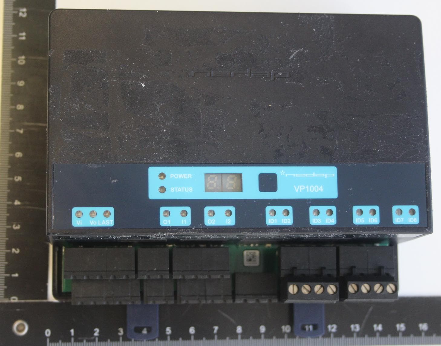
CGDVP1004B
Jan 25, 2021VP1004-B System
Equipment Class
DCD - Part 15 Low Power Transmitter Below 1705 kHz
CGDFERPH
Dec 15, 2020SMARTTAG EAR
Equipment Class
DXX - Part 15 Low Power Communication Device Transmitter
CGDNVR2001
Dec 01, 2020Reader for 120 kHz and 13.56 MHz cards and also NFC, QR and BT
Equipment Class
DCD - Part 15 Low Power Transmitter Below 1705 kHz
CGDBOOSTER11
Nov 30, 2020Long-range vehicle and driver identification tag
Equipment Class
DSR - Part 15 Remote Control/Security Device Transceiver
CGDVP1105B
Jul 05, 2020VP1105-B
Equipment Class
DXX - Part 15 Low Power Communication Device Transmitter