CHO-VCRFBRVIB CONNECT RF (Bridge)
PRÜFTECHNIK Condition Monitoring GmbH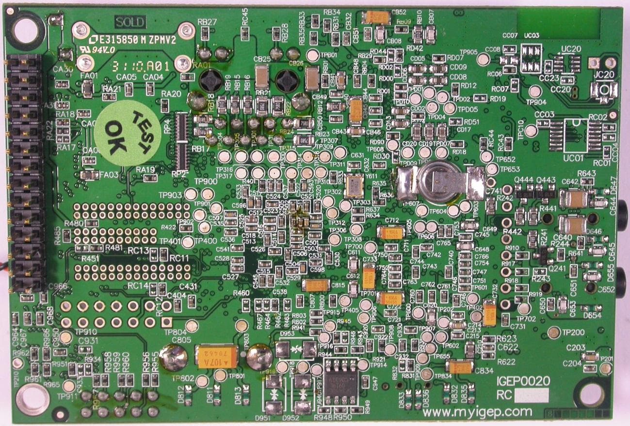
Click to zoom
Application Details
- Equipment Class
- DXX - Part 15 Low Power Communication Device Transmitter
- Date of Grant
- Jun 05, 2012
- Application Purpose
- Original Equipment
- Date of Application
- Jun 05, 2012
- Equipment Note
- VIB CONNECT RF (Bridge)
- Frequency Range
- 916.00000000 - 916.00000000
- Country
- Germany
Documents & Files
Document Text
Text extracted from the exhibit documents filed with the FCC. Open a document above to read the original.
Users Manual
VIBCONNECT ® RF Installation and Operation Compliance Statement acc. to Sect. 15.19: This device complies with Part 15 of the FCC Rules.Operation is subject to the following two conditions: (1) this device may not cause harmful interference, and (2) this device must accept any interference received, including interference that may cause un- desired operation. Le présent appareil est conforme aux CNR d'Industrie Canada applicables aux appareils radio exempts de licence. L'exploitation est autorisée aux deux conditions suivantes : (1) l'appareil ne doit pas produire de brouillage, et (2) l'utilisateur de l'appareil doit accepter tout brouillage radioélectrique subi, même si le brouillage est susceptible d'en compromettre le fonctionnement. User Information acc. to Sect.15.21: Changes or modifications not expressly approved by the party responsible for compliance could void the user’s authority to operate the equipment. Class B Statement Sect. 15.105 –) NOTE: This equipment has been tested and found to comply with the limits for a Class B digital device, pursuant to part 15 of the FCC Rules. These limits are designed to provide reasonable protection against harmful interference in a residential installation. This equipment generates, uses and can radiate radio frequency energy and, if not installed and used in accordance with the instructions, may cause harmful interference to radio communications. However, there is no guarantee that interference will not occur in a particular installation. If this equipment does cause harmful interference to radio or tel- evision reception, which can be determined by turning the equipment off and on, the user is encouraged to try to correct the interference by one or more of the following measures: • Reorient or relocate the receiving antenna. • Increase the separation between the equipment and receiver. • Connect the equipment into an outlet on a circuit different from that to which the receiver is connected. • Consult the dealer or an experienced radio/ TV technician for help. Installation and Operation VIBCONNECT ® RF Online Condition Monitoring with Radio Communication Date: November 2011 Prod. no.: LIT 72.200.DE Original manual Series: VIB 7.200 RF Bridge VIB 7.220 RF Sensor unit VIB 7.205-2.9 RF sensor Firmware : 1.x 4 VIBCONNECT RF 11.2011 The product described in this document, and the content of this manual are protect- ed by intellectual property laws. All rights reserved. The manual may not be copied, reproduced, translated or made accessible to a third party in any form, neither in its entirety nor as an excerpt. No liability may be claimed against the publisher regarding the product described in this manual. The author assumes no liability for accuracy of the manual contents. The author shall not be liable for any direct or indirect damage of any kind resulting from use of the product or the manual, even if the publisher has expressly indicated the potential for occurrence of such damage. The manufacturer shall not be liable for product defects. This warranty and liability limitation also applies to sales partners and distributors. All registered trademarks referred to in this manual are the property of the r espective owners. This applies also to trademarks that are not specifically denoted as such. © 2011 PRÜFTECHNIK Condition Monitoring. All rights reserved. 3 VIBCONNECT RF 11.2011 Foreword Thank you for purchasing our VIBCONNECT RF online condition monitoring system. VIBCONNECT RF offers maximum flexibility at minimum costs for installation and operation. It caters for the con- tinuous condition monitoring of machines for which wired systems would not be economically viable. System properties • Easy and fast installation without the need for wiring • Full integration in OMNITREND PC software • Each bridge caters for up to 50 sensor units • Each sensor unit comes with two fully wire dual sensors for vibra- tion and temperature • Allows for optimized positioning of the sensors and the radio transmission unit anywhere in the machine • Measurement of time signal • Calculation of amplitude and envelope spectra • Identification of broad and narrow band characteristic values • Powered by battery or 24 V power supply • Monitoring of battery charge • Can be equipped with energy harvester • IEEE 802.xxx compatible radio transmission If you require more information, you might wish to attend a PRÜF - TECHNIK seminar , which focuses on practical issues and has been found very useful by participants. Attending our seminars has proven to be a valuable investment for machine operators. To find out more, please contact us for seminar dates or visit our website at http://www.pruftechnik.com Ismaning, November 2011 PRÜFTECHNIK Condition Monitoring Foreword 4 VIBCONNECT RF 11.2011 Contents Contents Chapter 1: Introduction .....................................................7 1.1 First steps ........................................................................7 1.2 Service addresses ............................................................7 1.3 About this manual ..........................................................8 Chapter 2: Safety ...............................................................9 2.1 Safety symbols ...............................................................9 2.2 Information for the system operator ................................9 2.3 Information for operating personnel .............................10 Rules for normal operation ...........................................................10 2.4 Intended use .................................................................11 2.5 Residual risks and safety measures ................................12 Chapter 3: Technical data ................................................15 Chapter 4: System description ........................................19 4.1 VIBCONNECT RF bridge ................................................19 4.2 VIBCONNECT RF sensor unit ...............................…
Text truncated - open the document above for the full version.
Cover Letter(s)
Request for Confidentiality Date: 16.05.2012 Subject: Confidentiality Request for: FCC ID: CHO-VCRFBR IC: 10238A-VIBCONNECT ______ Pursuant to FCC 47 CRF 0.457(d) and 0.459 and IC RSP-100, Section 10, the applicant requests that a part of the subject FCC application be held confidential. Type of Confidentiality Requested Exhibit Short Term Permanent Block Diagrams Short Term External Photos Short Term Permanent* 1 Internal Photos Short Term Permanent Operation Description/Theory of Operation Short Term Permanent Parts List & Placement/BOM Short Term Permanent Tune-Up Procedure Short Term Permanent Schematics Short Term Test Setup Photos Short Term Permanent* User’s Manual *Note: ______(Insert Explanation as Necessary)______ PRUEFTECHNIK Condition Monitoring GmbH has spent substantial effort in developing this product and it is one of the first of its kind in industry. Having the subject information easily available to "competition" would negate the advantage they have achieved by developing this product. Not protecting the details of the design will result in financial hardship. Permanent Confidentiality: The applicant requests the exhibits listed above as permanently confidential be permanently withheld from public review due to materials that contain trade secrets and proprietary information not customarily released to the public. Short-Term Confidentiality: The applicant requests the exhibits selected above as short term confidential be withheld from public view for a period of (0) days from the date of the Grant of Equipment Authorization and prior to marketing. This is to avoid premature release of sensitive information prior to marketing or release of the product to the public. Applicant is also aware that they are responsible to notify ACB in the event information regarding the product or the product is made available to the public. ACB will then release the documents listed above for public disclosure pursuant to FCC Public Notice DA 04-1705. NOTE for Industry Canada Applications: The applicant understands that until such time that IC distinguishes between Short Term and Permanent Confidentiality, either type of marked exhibit above will simply be marked Confidential when submitted to IC. Sincerely, By: Manager Certification Thomas Ring 1 - The asterisked items (*) require further justification before permanent confidentiality will be allowed. These also currently require review by the FCC under their Permit-But-Ask policy before the grant is issued and can delay completion of an application. Further justification should be added to the note above. One such example for a potted device would be: “The EUT is FULLY potted using a non-removable epoxy based material. Removal of potting material causes irreparable damage to internal circuitry. See photographs exhibits that outline the device before and after potting.”
ID Label/Location Info
Label FCC / Sensor Unit EDV-Nummer 0 0578 0141 Fertiger: Riebl Siebdruck VIBCONNECT RF Beschriftung FCC 15.5.2012 RD Label FCC / Bridge EDV-Nummer <neu anzulegen> Fertiger: Riebl Siebdruck Old Version, now obsolete: FCC ID: CHO-VCRFBR IC: 10238A-VIBCONNECT Model: Bridge VIB7.220 FCC ID: CHO-VCRFSU IC: 10238A-VIBCONNECT Model: Sensor Unit VIB7.200 Sensor Unit Standard Label w ritten via laser m arker on top Standard Label Bridge Standard Label Power Das zusätzliche FCC/IC-Label wird nur in der US-Variante VIB 7.220 aufgeklebt Das zusätzliche FCC/IC-Label wird nur in der US-Variante VIB 7.200 aufgeklebt. additional Label FCC / Bridge additional Label FCC / Sensor Unit
Internal Photos
mikes-testingpartners gmbh File No. T35772-00HU, page 5 of 16 Ohmstrasse 2-4 94342 STRASSKIRCHEN GERMANY Tel.: +49(0)9424-94810 Fax: +49(0)9424-9481240 1.2 Internal views – Bridge: mikes-testingpartners gmbh File No. T35772-00HU, page 6 of 16 Ohmstrasse 2-4 94342 STRASSKIRCHEN GERMANY Tel.: +49(0)9424-94810 Fax: +49(0)9424-9481240 Circuit board 1: mikes-testingpartners gmbh File No. T35772-00HU, page 7 of 16 Ohmstrasse 2-4 94342 STRASSKIRCHEN GERMANY Tel.: +49(0)9424-94810 Fax: +49(0)9424-9481240 mikes-testingpartners gmbh File No. T35772-00HU, page 8 of 16 Ohmstrasse 2-4 94342 STRASSKIRCHEN GERMANY Tel.: +49(0)9424-94810 Fax: +49(0)9424-9481240 Circuit board 2: mikes-testingpartners gmbh File No. T35772-00HU, page 9 of 16 Ohmstrasse 2-4 94342 STRASSKIRCHEN GERMANY Tel.: +49(0)9424-94810 Fax: +49(0)9424-9481240 Side views Circuit Board 2:
Test Report
FCC ID: CHO-VCRFBR mikes-testingpartners gmbh File No. T35772-00-05HU, page 1 of 26 Ohmstrasse 2-4 94342 STRASSKIRCHEN GERMANY Tel.:+49(0)9424-94810 Fax:+49(0)9424-9481240 Rev. No. 1.2, 9.9.2010 EMI − T E S T R E P O R T - FCC Part 15.249 - Test Report No. : T35772-00-05HU 16. May 2012 ______________________________________________________________________________________________ Date of issue Type / Model Name : VIBCONNECT RF Bridge Product Description : Industrial Data Acquisition System Applicant : PRÜFTECHNIK Condition Monitoring GmbH Address : Oskar-Messter-Str. 19-21 D-85737 Ismaning Manufacturer : PRÜFTECHNIK Condition Monitoring GmbH Address : Oskar-Messter-Str. 19-21 D-85737 Ismaning Licence holder : PRÜFTECHNIK Condition Monitoring GmbH Address : Oskar-Messter-Str. 19-21 D-85737 Ismaning Test Result according to the standards listed in clause 1 test standards: POSITIVE The test report merely corresponds to the test sample. It is not permitted to copy extracts of these test results without the written permission of the test laboratory. FCC ID: CHO-VCRFBR mikes-testingpartners gmbh File No. T35772-00-05HU, page 2 of 26 Ohmstrasse 2-4 94342 STRASSKIRCHEN GERMANY Tel.:+49(0)9424-94810 Fax:+49(0)9424-9481240 Rev. No. 1.2, 9.9.2010 Contents 1 T E S T S T A N D A R D S 3 2 S U M M A R Y 4 3 E Q U I P M E N T U N D E R T E S T 5 3.1 Photo documentation of the EUT – Please see attachment A 5 3.2 Power supply system utilised 6 3.3 Short description of the equipment under test (EUT) 6 4 T E S T E N V I R O N M E N T 7 4.1 Address of the test laboratory 7 4.2 Environmental conditions 7 4.3 Statement of the measurement uncertainty 7 4.4 Measurement protocol for FCC 7 5 T E S T C O N D I T I O N S A N D R E S U L T S 10 5.1 Conducted emissions 10 5.2 Radiated emission of the fundamental wave 16 5.3 Spurious emissions radiated 18 5.4 Emission Bandwidth 21 5.5 Antenna application 23 5.6 Receiver radiated emissions 24 6 U S E D T E S T E Q U I P M E N T A N D A C C E S S O R I E S 26 FCC ID: CHO-VCRFBR mikes-testingpartners gmbh File No. T35772-00-05HU, page 3 of 26 Ohmstrasse 2-4 94342 STRASSKIRCHEN GERMANY Tel.:+49(0)9424-94810 Fax:+49(0)9424-9481240 Rev. No. 1.2, 9.9.2010 1 T E S T S T A N D A R D S The tests were performed according to following standards: FCC Rules and Regulations Part 15, Subpart A - General (September, 2011) Part 15, Subpart A, Section 15.31 Measurement standards Part 15, Subpart A, Section 15.33 Frequency range of radiated measurements Part 15, Subpart A, Section 15.35 Measurement detector functions and bandwidths FCC Rules and Regulations Part 15, Subpart C - Intentional Radiators (September, 2011) Part 15, Subpart C, Section 15.203 Antenna requirement Part 15, Subpart C, Section 15.204 External radio frequency power amplifiers and antenna modifications Part 15, Subpart C, Section 15.205 Restricted bands of operation Part 15, Subpart C, Section 15.207 Conducted limits Part 15, Subpart C, Section 15.209 Radiated emission limits, general requirements Part 15, Subpart C, Section 15.249 Operation within the bands 902 - 928 MHz, 2400 - 2483.5 MHz, 5725 - 5875 MHz, and 24.0 - 24.25 GHz ANSI C63.4: 2003 Methods of Measurement of Radio-Noise Emissions from Low- Voltage Electrical and Electronic Equipment in the Range of 9 kHz to 40 GHz. ANSI C95.1:2005 IEEE Standard for Safety Levels with respect to Human Exposure to Radio Frequency Electromagnetic Fields, 3 kHz to 300 GHz CISPR 16-4-2: 2003 Uncertainty in EMC measurement CISPR 22: 2005 Information technology equipment EN 55022: 2006 FCC ID: CHO-VCRFBR mikes-testingpartners gmbh File No. T35772-00-05HU, page 4 of 26 Ohmstrasse 2-4 94342 STRASSKIRCHEN GERMANY Tel.:+49(0)9424-94810 Fax:+49(0)9424-9481240 Rev. No. 1.2, 9.9.2010 2 S U M M A R Y GENERAL REMARKS: The manufacturer declared that the transmitter / receiver circuit is identical in Bridge and Sensor Unit and is based on the IC Atmel AT86RF212. Tests were performed with Sensor Unit as a system. It is not possible to set the EuT only in receiving mode. FINAL ASSESSMENT: The equipment under test fulfills the EMI requirements cited in clause 1 test standards. Date of receipt of test sample : acc. to storage records Testing commenced on : 18. January 2012 Testing concluded on : 21. February 2012 Checked by: Tested by: Thomas Weise Dipl. Ing.(FH) Laboratory Manager Markus Huber FCC ID: CHO-VCRFBR mikes-testingpartners gmbh File No. T35772-00-05HU, page 5 of 26 Ohmstrasse 2-4 94342 STRASSKIRCHEN GERMANY Tel.:+49(0)9424-94810 Fax:+49(0)9424-9481240 Rev. No. 1.2, 9.9.2010 3 E Q U I P M E N T U N D E R T E S T 3.1 Photo documentation of the EUT – Please see attachment A FCC ID: CHO-VCRFBR mikes-testingpartners gmbh File No. T35772-00-05HU, page 6 of 26 Ohmstrasse 2-4 94342 STRASSKIRCHEN GERMANY Tel.:+49(0)9424-94810 Fax:+49(0)9424-9481240 Rev. No. 1.2, 9.9.2010 3.2 Power supply system utilised Power supply voltage, Bridge : Primary: 110V / 60 Hz Secondary: 5.0 V / DC 3.3 Short description of the equipment under test (EUT) The Industrial Data Acquisition System consists of a sensor unit and a bridge. The "Sensor Unit" collects with two accelerometers data’s and transmit them via wireless to the "Bridge" which will transfer them via Ethernet to a host computer. The radio link is bidirectional, half duplex. Number of tested samples: 1 System (Bridge & Sensor Unit) Serial number: see Photo documentation of the EuT under Point 3 / Equipment Under Test EUT operation mode: The equipment under test was operated during the measurement under the following conditions: - Tx mode at 916 MHz - - EUT configuration: The following peripheral devices and interface cables were connected during the measurements: - Model : - Model : - Model : - Model : - Model : - Model : FCC ID: CHO-VCRFBR mikes-testingpartners gmbh File No. T35772-00-05HU, page 7 of 26 Ohmstrasse 2-4 94342 STRASSKIRCHEN GERMANY Tel.:+49(0)9424-94810 Fax:+49(0)9424-9481240 Rev. No. 1.2, 9.9.20…
Text truncated - open the document above for the full version.
Test Setup Photos
FCC ID: CHO-VCRFBR mikes-testingpartners gmbh File No. T35772-00-05HU, page 10 of 26 Ohmstrasse 2-4 94342 STRASSKIRCHEN GERMANY Tel.:+49(0)9424-94810 Fax:+49(0)9424-9481240 Rev. No. 1.2, 9.9.2010 5 T E S T C O N D I T I O N S A N D R E S U L T S 5.1 Conducted emissions For test instruments and accessories used see section 6 Part A 4. 5.1.1 Description of the test location Test location: Shielded Room S2 5.1.2 Photo documentation of the test set-up 5.1.3 Applicable standard According to FCC Part 15, Section 15.207(a): Except as shown in paragraphs (b) and (c) of this Section, for an intentional radiator that is designed to be connected to the public utility (AC) power line, the radio frequency voltage that is conducted back onto the AC power line on any frequency or frequencies within the band 150 kHz to 30 MHz shall not exceed the given limits. 5.1.4 Description of Measurement The measurements are performed following the procedures set out in ANSI C63.4 described under item 4.4.3. If the minimum limit margin appears to be less than 20 dB with a peak mode measurement, the emissions are remeasured using a tuned receiver with quasi-peak and average detection and recorded on the data sheets. 5.1.5 Test result Frequency range: 0.15 MHz - 30 MHz Min. limit margin 2.8 dB at 7.985 MHz (N, normal operation mode) FCC ID: CHO-VCRFBR mikes-testingpartners gmbh File No. T35772-00-05HU, page 16 of 26 Ohmstrasse 2-4 94342 STRASSKIRCHEN GERMANY Tel.:+49(0)9424-94810 Fax:+49(0)9424-9481240 Rev. No. 1.2, 9.9.2010 5.2 Radiated emission of the fundamental wave For test instruments and accessories used see section 6 Part CPR 2. 5.2.1 Description of the test location Test location: OATS1 Test distance: 3 metres 5.2.2 Photo documentation of the test set-up Bridge Unit: FCC ID: CHO-VCRFBR mikes-testingpartners gmbh File No. T35772-00-05HU, page 18 of 26 Ohmstrasse 2-4 94342 STRASSKIRCHEN GERMANY Tel.:+49(0)9424-94810 Fax:+49(0)9424-9481240 Rev. No. 1.2, 9.9.2010 5.3 Spurious emissions radiated For test instruments and accessories used see section 6 Part SER 1, SER 2, SER 3. 5.3.1 Description of the test location Test location: OATS1 Test location: Anechoic Chamber A2 Test distance: 3 metres 5.3.2 Photo documentation of the test set-up FCC ID: CHO-VCRFBR mikes-testingpartners gmbh File No. T35772-00-05HU, page 21 of 26 Ohmstrasse 2-4 94342 STRASSKIRCHEN GERMANY Tel.:+49(0)9424-94810 Fax:+49(0)9424-9481240 Rev. No. 1.2, 9.9.2010 5.4 Emission Bandwidth For test instruments and accessories used see section 6 Part MB. 5.4.1 Description of the test location Test location: AREA4 5.4.2 Photo documentation of the test set-up 5.4.3 Applicable standard According to FCC Part 15, Section 15.215(c): Intentional radiators operating under the provisions to the general emission limits, as contained in Section 15.217 through Section 15.257, must designed to ensure that the 20 dB bandwidth of the emission is contained within the frequency band is designated in the rule section under which the equipment is operated. 5.4.4 Description of Measurement The bandwidth is measured at an amplitude level reduced from the reference level by a specified ratio of -20 dB. The reference level is the level of the highest signal amplitude observed from the transmitter at the fundamental frequency. Alternative is the x-dB-down function of the analyser used. The EBW is than directly shown in the marker display. The measurement is performed with normal modulation and a transfer rate means the worst case. Spectrum analyser settings see protocol: 5.4.5 Test result Fundamental [MHz] 20dB Bandwidth F1 [MHz] 20dB Bandwidth F2 [MHz] Measured Bandwidth [MHz] 916.0 915.38 916.66 1.28 80% bandwidth of the permitted band (902 – 928 MHz): 20.8 MHz
Contact Information
Applicant
Rainer Hawranke
Technical Contact
Test Firm
CSA Group Bayern GmbHThomas Weise
Technical Specifications
| # | Rule Parts | Frequency Range | Power Output |
|---|---|---|---|
| 1 | 15C | 916 MHz - 916 MHz | - |
Other Applications from PRÜFTECHNIK Condition Monitoring GmbH
CHO-VCRFBR24
Mar 05, 2014VIB CONNECT RF Bridge / Industrial Data Acquisition System
Equipment Class
DTS - Digital Transmission System
CHO-VCRFSU24
Feb 25, 2014VIB CONNECT RF Sensor Unit / Industrial Data Acquisition System
Equipment Class
DTS - Digital Transmission System
CHO-VCRFSU
Jun 05, 2012VIB CONNECT RF (Sensor Unit)
Equipment Class
DXX - Part 15 Low Power Communication Device Transmitter