CHO-VCRFSU24VIB CONNECT RF Sensor Unit / Industrial Data Acquisition System
PRÜFTECHNIK Condition Monitoring GmbH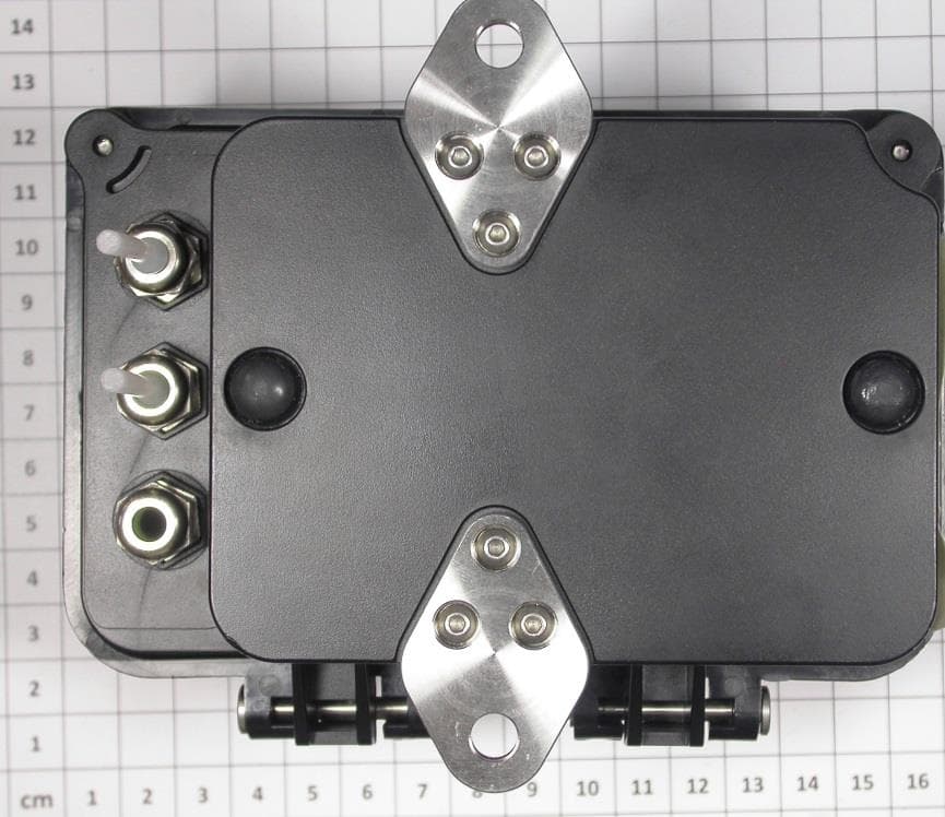
Click to zoom
Application Details
- Equipment Class
- DTS - Digital Transmission System
- Date of Grant
- Feb 25, 2014
- Application Purpose
- Original Equipment
- Date of Application
- Feb 24, 2014
- Equipment Note
- VIB CONNECT RF Sensor Unit / Industrial Data Acquisition System
- Frequency Range
- 2435.20000000 - 2435.20000000
- Country
- Germany
Documents & Files
Document Text
Text extracted from the exhibit documents filed with the FCC. Open a document above to read the original.
Users Manual
Preliminary manual / shortform for the VIBCONNECT RF 868/915MHz. For VIBCONNECT RF 2.4GHz necessary changes will be made. ----------------------------------------- New text on page II : a) User Information gem. FCC 15.21 enthalten: Changes or modifications not expressly approved by the party responsible for compliance could void the user’s authority to operate the equipment. b) Part 15 Statement gem. FCC 15.19/RSS Gen Issue 3 Sect. 7.1.3 This device complies with Part 15 of the FCC Rules and with Industry Canada license-exempt RSS standard(s). Operation is subject to the following two conditions: (1) this device may not cause harmful interference, and (2) this device must accept any interference received, including interference that may cause undesired operation. Le présent appareil est conforme aux CNR d'Industrie Canada applicables aux appareils radio exempts de licence. L'exploitation est autorisée aux deux conditions suivantes : (1) l'appareil ne doit pas produire de brouillage, et (2) l'utilisateur de l'appareil doit accepter tout brouillage radioélectrique subi, même si le brouillage est susceptible d'en compromettre le fonctionnement. c) Statement für Class B Digital Device gem. FCC 15.105: NOTE: This equipment has been tested and found to comply with the limits for a Class B digital device, pursuant to part 15 of the FCC Rules. These limits are designed to provide reasonable protection against harmful interference in a residential installation. This equipment generates, uses and can radiate radio frequency energy and, if not installed and used in accordance with the instructions, may cause harmful interference to radio communications. However, there is no guarantee that interference will not occur in a particular installation. If this equipment does cause harmful interference to radio or television reception, which can be determined by turning the equipment off and on, the user is encouraged to try to correct the interference by one or more of the following measures: —Reorient or relocate the receiving antenna. —Increase the separation between the equipment and receiver. —Connect the equipment into an outlet on a circuit different from that to which the receiver is connected. —Consult the dealer or an experienced radio/ TV technician for help. ----------------------------------------- Postion of FCC-label is not shown on page 15/16 this will be changed in the next version of the manual. Preliminary manual / shortform for the VIBCONNECT RF 868/915MHz. For VIBCONNECT RF 2.4GHz necessary changes will be made. -----------------------------------------
Cover Letter(s)
American Certification Body Inc. 6731 Whittier Ave, Suite C110 McLean, VA22101 Date: 12.02.2014 Model: Sensor Unit VIB 7.205 FCC ID: CHO-VCRFSU24 IC: 10238A-VCRFSU24 Model: Bridge VIB 7.225 FCC ID: CHO-VCRFBR24 IC: 10238A-VCRFBR24 Reverse Polarity SMA This is to confirm, the devices Sensor Unit VIB 7.205 (2.4 GHz) / Bridge VIB 7.225 (2.4 GHz) will be produced with antenna connection reverse polarity SMA. If you have any questions, please feel free to contact me at the address shown below. Yours sincerely, Thomas Ring Manager Certification CSA Group Bayern GmbH Ohmstr. 1-4 94342 Strasskirchen Germany
External Photos
Attachment A to File No.: T37567-00 1 P h o t o d o c u m e n t a t i o n o f t h e E U T 1.1 External views:
ID Label/Location Info
VIBCONNECT RF 2.4GHz 1 10.12.2013 RD antenna type: ANT-2.4-CW-HWR-SMA manufacturer: „Antenna Factor“ SensorUnit VIB 7.205 PCB Funkmodul C 0 3022 1110 PCB Power Platine Battery 0 3022 1106 FCC label PCB Hauptplatine 0 3022 1097 2 main board power board transceiver Sensor Unit Sensoren VIB 7.205-2.9 Hauptplatine Funkmodul
Internal Photos
Attachment A to File No.: T37567-00 1 P h o t o d o c u m e n t a t i o n o f t h e E U T 1.1 Internal views:
Test Report
FCC ID: CHO-VCRFSU24 IC ID: 10238A-VCRFSU24 CSA Group Bayern GmbH File No. T37568-00-00HU, page 1 of 42 Ohmstrasse 1-4 94342 STRASSKIRCHEN GERMANY Tel.:+49(0)9424-94810 Fax: ++49(0)9424-9481440 Rev. No. 3.0, 2014-01-31 EMI − T E S T R E P O R T - FCC Part 15.247, RSS210 - Test Report No. : T37568-00-00HU 13. February 2014 ______________________________________________________________________________________________ Date of issue Type / Model Name : VIBCONNECT RF Sensor Unit - VIB 7.225 Product Description : Industrial Data Acquisition System Applicant : PRÜFTECHNIK Condition Monitoring GmbH Address : Oskar-Messter-Str. 19-21 D-85737 Ismaning Manufacturer : PRÜFTECHNIK Condition Monitoring GmbH Address : Oskar-Messter-Str. 19-21 D-85737 Ismaning Licence holder : PRÜFTECHNIK Condition Monitoring GmbH Address : Oskar-Messter-Str. 19-21 D-85737 Ismaning Test Result according to the standards listed in clause 1 test standards: POSITIVE The test report merely corresponds to the test sample. It is not permitted to copy extracts of these test results without the written permission of the test laboratory. FCC ID: CHO-VCRFSU24 IC ID: 10238A-VCRFSU24 CSA Group Bayern GmbH File No. T37568-00-00HU, page 2 of 42 Ohmstrasse 1-4 94342 STRASSKIRCHEN GERMANY Tel.:+49(0)9424-94810 Fax: ++49(0)9424-9481440 Rev. No. 3.0, 2014-01-31 Contents 1 T E S T S T A N D A R D S 3 2 S U M M A R Y 4 2.1 Test result summery 4 2.2 General remarks 5 2.3 Final assessment 5 3 E Q U I P M E N T U N D E R T E S T 6 3.1 Photo documentation of the EUT – Detailed photos see attachment A 6 3.2 Power supply system utilised 6 3.3 Short description of the equipment under test (EUT) 6 4 T E S T E N V I R O N M E N T 7 4.1 Address of the test laboratory 7 4.2 Environmental conditions 7 4.3 Statement of the measurement uncertainty 7 4.4 Measurement protocol for FCC and IC 8 5 T E S T C O N D I T I O N S A N D R E S U L T S 10 5.1 Conducted emissions 10 5.2 Emission bandwidth 11 5.3 Occupied bandwidth 14 5.4 Maximum peak conducted output power 16 5.5 Spurious emissions conducted 19 5.7 Spurious emissions radiated 27 5.8 Power spectral density 31 5.9 Maximum permissible exposure (MPE) 35 5.11 Antenna application 38 5.13 Receiver radiated emissions 39 6 U S E D T E S T E Q U I P M E N T A N D A C C E S S O R I E S 42 FCC ID: CHO-VCRFSU24 IC ID: 10238A-VCRFSU24 CSA Group Bayern GmbH File No. T37568-00-00HU, page 3 of 42 Ohmstrasse 1-4 94342 STRASSKIRCHEN GERMANY Tel.:+49(0)9424-94810 Fax: ++49(0)9424-9481440 Rev. No. 3.0, 2014-01-31 1 T E S T S T A N D A R D S The tests were performed according to following standards: FCC Rules and Regulations Part 15, Subpart A - General (October, 2013) Part 15, Subpart A, Section 15.31 Measurement standards Part 15, Subpart A, Section 15.33 Frequency range of radiated measurements Part 15, Subpart A, Section 15.35 Measurement detector functions and bandwidths FCC Rules and Regulations Part 15 Subpart B - Unintentional Radiators (October, 2013) Part 15, Subpart B, Section 15.107 AC Line conducted emission Class A device Class B device Part 15, Subpart B, Section 15.109 Radiated emission, general requirements FCC Rules and Regulations Part 15, Subpart C - Intentional Radiators (October, 2013) Part 15, Subpart C, Section 15.203 Antenna requirement Part 15, Subpart C, Section 15.204 External radio frequency power amplifiers and antenna modifications Part 15, Subpart C, Section 15.205 Restricted bands of operation Part 15, Subpart C, Section 15.207 Conducted limits Part 15, Subpart C, Section 15.209 Radiated emission limits, general requirements Part 15, Subpart C, Section 15.247 Operation within the bands 902 - 928 MHz, 2400 - 2483.5 MHz and 5725 - 5850 MHz FCC Rules and Regulations Part 1, Subpart I - Procedures Implementing the National Environmental Policy Act of 1969 Part 1, Subpart I, Section 1.1310 Radiofrequency radiation exposure limits Part 1, Subpart 2, Section 2.1093 Radiofrequency radiation exposure evaluation: portable device OET Bulletin 65, 65A, 65B, 65C Edition 97-01, August 1997 – Evaluating Compliance with FCC Guidelines for Human Exposure to Radio Frequency Electromagnetic Fields. ANSI C63.4: 2003 Methods of Measurement of Radio-Noise Emissions from Low- Voltage Electrical and Electronic Equipment in the Range of 9 kHz to 40 GHz. ANSI C95.1: 2005 IEEE Standard for Safety Levels with respect to Human Exposure to Radio Frequency Electromagnetic Fields, 3 kHz to 300 GHz CISPR 16-4-2: 2003 Uncertainty in EMC measurement CISPR 22: 2005 Information technology equipment EN 55022: 2006 KDB 558074 D01 Guidance for performing compliance measurements on DTS operating under Section 15.247, v03r01 of April 9, 2013. FCC ID: CHO-VCRFSU24 IC ID: 10238A-VCRFSU24 CSA Group Bayern GmbH File No. T37568-00-00HU, page 4 of 42 Ohmstrasse 1-4 94342 STRASSKIRCHEN GERMANY Tel.:+49(0)9424-94810 Fax: ++49(0)9424-9481440 Rev. No. 3.0, 2014-01-31 2 S U M M A R Y 2.1 Test result summery FCC Rule Part RSS Rule Part Description Result 15.207(a) RSS Gen, 7.2.4. AC power line conducted emissions not applicable 15.247(a)(2) RSS210, A8.2(a) -6 dB EBW passed 15.247(b)(3) RSS-210, A8.4(4) Peak power passed 15.247(d) RSS-210, A8.5 Out-of-band emission, radiated passed 15.247(d) RSS-Gen, 7.2.2 Emissions in restricted bands passed 15.247(e) RSS-210, A8.2(b) PSD passed 15.35(c) RSS-Gen, 4.5 Pulsed operation not applicable 15.247(i) RSS 102, 2.5.2 MPE passed 15.247(b)(4) RSS-Gen, 7.1.2 Antenna requirement passed 15.107 RSS Gen, 7.2.4. AC power line conducted emissions not applicable 15.109(a) RSS-Gen, 6.1 Receiver spurious emissions, radiated passed RSS-Gen, 7.2.6 Transmitter frequency stability not applicable RSS-Gen, 4.6.1 99 % Bandwidth passed OET Bulletin 65 RSS102, 3.2 Co-location, Co-transmission not applicable AC powerline conducted emission measurement is not applicable. The device has no AC mains connection and is separated powered by two 3.6 V / DC batteries. The mentioned RSS Rule Parts in the above t…
Text truncated - open the document above for the full version.
Test Setup Photos
FCC ID: CHO-VCRFSU24 IC ID: 10238A-VCRFSU24 CSA Group Bayern GmbH File No. T37568-00-00HU, page 11 of 42 Ohmstrasse 1-4 94342 STRASSKIRCHEN GERMANY Tel.:+49(0)9424-94810 Fax: ++49(0)9424-9481440 Rev. No. 3.0, 2014-01-31 5.2 Emission bandwidth For test instruments and accessories used see section 6 Part MB. 5.2.1 Description of the test location Test location: AREA4 5.2.2 Photo documentation of the test set-up , 5.2.3 Applicable standard According to FCC Part 15, Section 15.247(a)(2): Systems using digital modulation techniques may operate in the 902 - 928 MHz, 2400 – 2483.5 MHz and 5725 – 5850 MHz bands. The minimum 6 dB bandwidth shall be at least 500 kHz. 5.2.4 Description of Measurement The bandwidth was measured at an amplitude level reduced from the reference level of a modulated channel by a ratio of -6 dB. The reference level is the level of the highest signal amplitude observed at the transmitter at either the fundamental frequency or the first order modulation products in all typical modes of operation, including the unmodulated carrier, even if atypical. An alternative is to use the bandwidth measurement of the analyser. FCC ID: CHO-VCRFSU24 IC ID: 10238A-VCRFSU24 CSA Group Bayern GmbH File No. T37568-00-00HU, page 14 of 42 Ohmstrasse 1-4 94342 STRASSKIRCHEN GERMANY Tel.:+49(0)9424-94810 Fax: ++49(0)9424-9481440 Rev. No. 3.0, 2014-01-31 5.3 Occupied bandwidth For test instruments and accessories used see section 6 Part MB. 5.3.1 Description of the test location Test location: AREA4 5.3.2 Photo documentation of the test set-up 5.3.1 Applicable standard According to RSS-Gen, 4.6.1: When an occupied bandwidth value is not specified in the applicable RSS, the transmitted signal bandwidth to be reported is to be its 99 % emission bandwidth, as calculated or measured. 5.3.2 Description of Measurement The bandwidth was measured with the function “bandwidth measurement” of the spectrum analyser. The EUT is connected via suitable attenuator at the spectrum analyser. The measurement is repeated for every different modulation standard of the EUT and recorded. FCC ID: CHO-VCRFSU24 IC ID: 10238A-VCRFSU24 CSA Group Bayern GmbH File No. T37568-00-00HU, page 16 of 42 Ohmstrasse 1-4 94342 STRASSKIRCHEN GERMANY Tel.:+49(0)9424-94810 Fax: ++49(0)9424-9481440 Rev. No. 3.0, 2014-01-31 5.4 Maximum peak conducted output power For test instruments and accessories used see section 6 Part CPC 3. 5.4.1 Description of the test location Test location: AREA4 5.4.2 Photo documentation of the test set-up 5.4.3 Applicable standard According to FCC Part 15, Section 15.247(b)(3): For systems using digital modulation in the 902 – 928 MHz, 2400-2483.5 MHz and 5725 – 5850 MHz bands, the maximum peak output power of the transmitter shall not exceed 1 Watt. The limit is based on transmitting antennas of directional gain that do not exceed 6 dBi. 5.4.4 Description of Measurement The EuT was fixed mounted on the receiving antenna of the spectrum analyzer to find out the maximum power. An analyzer offset was tried to see the compliance to the measured radiated value. The transmitter output was directly connected to the spectrum analyzer. The center frequency of the spectrum analyzer is set to the fundamental frequency. The span of the spectrum analyzer should be larger than the emission bandwidth (EBW). The channel bandwidth has been set to EBW. With peak detector and power mode “Max Hold” the result is the summed maximum output power of the EBW. FCC ID: CHO-VCRFSU24 IC ID: 10238A-VCRFSU24 CSA Group Bayern GmbH File No. T37568-00-00HU, page 19 of 42 Ohmstrasse 1-4 94342 STRASSKIRCHEN GERMANY Tel.:+49(0)9424-94810 Fax: ++49(0)9424-9481440 Rev. No. 3.0, 2014-01-31 5.5 Spurious emissions conducted For test instruments and accessories used see section 6 Part SEC 1, SEC 2 and SEC 3. 5.5.1 Description of the test location Test location: Anechoic chamber 2 5.5.2 Photo documentation of the test set-up 5.5.3 Applicable standard According to FCC Part 15C, Section 15.247(d): In any 100 kHz bandwidth outside the used frequency band, the digitally modulated radio frequency power that is produced by the intentional radiator shall be at least 20 dB below that in the 100 kHz bandwidth within the band that contains the highest level of the desired power, based on either an RF conducted or an radiated measurement. Attenuation below the general limits specified in Section 15.209(a) is not required. In addition, radiated emissions which fall in the restricted bands, as defined in Section 15.205(a), must also comply with the radiated emission limit specified in Section 15.209(a). 5.5.4 Description of measurement A spectrum analyzer is connected to the output of the transmitter while EUT was operating in transmit mode at the assigned frequency. FCC ID: CHO-VCRFSU24 IC ID: 10238A-VCRFSU24 CSA Group Bayern GmbH File No. T37568-00-00HU, page 27 of 42 Ohmstrasse 1-4 94342 STRASSKIRCHEN GERMANY Tel.:+49(0)9424-94810 Fax: ++49(0)9424-9481440 Rev. No. 3.0, 2014-01-31 5.7 Spurious emissions radiated For test instruments and accessories used see section 6 Part SER 1, SER 2, SER 3. 5.7.1 Description of the test location Test location: OATS 1 Test location: Anechoic chamber 2 Test distance: 3 m 5.7.2 Photo documentation of the test set-up Open area test site FCC ID: CHO-VCRFSU24 IC ID: 10238A-VCRFSU24 CSA Group Bayern GmbH File No. T37568-00-00HU, page 28 of 42 Ohmstrasse 1-4 94342 STRASSKIRCHEN GERMANY Tel.:+49(0)9424-94810 Fax: ++49(0)9424-9481440 Rev. No. 3.0, 2014-01-31 Anechoic chamber 5.7.3 Applicable standard According to FCC Part 15, Section 15.247(d): In any 100 kHz bandwidth outside the frequency bands 902 – 928 MHz, 2400 – 2483.50 MHz and 5725 – 5850 MHz, the digitally modulated radio frequency power that is produced by the intentional radiator shall be at least 20 dB below that in the 100 kHz bandwidth within the band that contains the highest level of the desired power, based on either an RF conducted or an ra…
Text truncated - open the document above for the full version.
Contact Information
Applicant
Rainer Hawranke
Technical Contact
CSA Group Bayern GmbHMarkus Huber
[email protected]49 9424 9481
Ohmstrasse 1-4 · Strasskirchen · Germany
Test Firm
CSA Group Bayern GmbHThomas Weise
Technical Specifications
| # | Rule Parts | Frequency Range | Power Output |
|---|---|---|---|
| 1 | 15C | 2.44 GHz - 2.44 GHz | 1.86 mW |
Other Applications from PRÜFTECHNIK Condition Monitoring GmbH
CHO-VCRFBR24
Mar 05, 2014VIB CONNECT RF Bridge / Industrial Data Acquisition System
Equipment Class
DTS - Digital Transmission System
CHO-VCRFSU
Jun 05, 2012VIB CONNECT RF (Sensor Unit)
Equipment Class
DXX - Part 15 Low Power Communication Device Transmitter
CHO-VCRFBR
Jun 05, 2012VIB CONNECT RF (Bridge)
Equipment Class
DXX - Part 15 Low Power Communication Device Transmitter