CJJ79XITS-7045Model: BTS-7010 Multi-Channel MMDS/ITFS Booster
Axcera
Click to zoom
Application Details
- Equipment Class
- AMP - Amplifier
- Date of Grant
- Dec 02, 2001
- Application Purpose
- Original Equipment
- Date of Application
- Aug 20, 2001
- Equipment Note
- Model: BTS-7010 Multi-Channel MMDS/ITFS Booster
- Frequency Range
- 2500.00000000 - 2690.00000000
- Company
- Axcera
- Country
- United States
Documents & Files
Document Text
Text extracted from the exhibit documents filed with the FCC. Open a document above to read the original.
Users Manual
TELECOMMUNICATIONS TECHNICAL MANUAL EXHIBIT II (PRELIMINARY) BTS-7010 MULTI-CHANNEL (BROADBAND) BOOSTER REV: 0 102 Rahway Road McMurray, PA 15317 USA Phone 412-941-1500 FAX 412-941-9421 ADC BTS-7010 MULTI-CHANNEL BOOSTER TABLE OF CONTENTS I.INTRODUCTION: II.SYSTEM BTS-7010: A.SYSTEM DISCRIPTION B. SPECIFICATIONS C. INSTALLATION PROCEDURE IIIOPERATION BTS-7010: A. SYSTEM CHECK OUT AND OPERATION B. INITIAL TURN ON C. NORMAL OPERATION D. SYSTEM MONITORING AND CONTROL (Control Monitoring Sled) E. REAR PANEL CONNECTIONS F. FRONT PANEL LED INDICATORS G. MAINTENANCE AND TROUBLE SHOOTING IVDRAWINGS A. SYSTEM DRAWINGS: BLOCK DIAGRAM ........................................................................................................................... 1509-3100 B.SLED SUBASSEMBLIES SYSTEM DESCRIPTION The BTS-7010 Multi-Channel Booster is a digital broadband booster designed to operate with a maximum of four simultaneous input signals. The BTS-7010 is capable of operating as a wireless video/data transmitter at a nominal power level of 5.0 watts (total average). The unit is comprised of a 64 QAM modulator (Vyyo V300 Wireless Modem Termination System), frequency agile QAM upconverter (Wavecom MA4040D) and BTS-7010 Multi-Channel Booster. The WMTS receives full duplex Ethernet data frames (100BaseT), multiplexes the signal in TDM and modulates the signal to a 64 QAM, 44 MHz IF carrier. The IF output from the QAM modulator is upconverted to the superband (222 to 408 MHz) frequency of the desired channel by the QAM upconverter then directed to the input to the multi-channel booster where it is upconverted and amplified to the MMDS/ITFS frequency range (2500.00 MHz to 2690.00 MHz). The unit is utilizes ALC circuitry to automatically maintain output power and is designed to operate in a system with other identical booster units in an N+1 redundant configuration. This manual covers the description, installation, set-up, operation, schematic and interconnect drawings, as well as other useful technical information. TECHNICAL MANUAL DESCRIPTION This manual has been provided to assist with the set-up, operation, and maintenance of the transmitter. This manual also offers a brief system description, block diagrams, interconnect, front panel description, rear panel description, and a specification sheet. If after reviewing this manual, you still have questions, please contact the ADC Service Company at (724) 941-1500. A Customer Service Technician will be glad to assist you. SPECIFICATIONS: BTS-7010 Type of Emissions .................................................................................................... BOOSTER Frequency Range ....................... (4 simultaneous channel operation maximum) 2500 to 2690 MHz Output Power Rating ............................................................................ 5.0 watts (total average) DC voltage and total current of final amplifier stage ................................ 12 volts DC at 38 amps (Class A - Not RF power dependent) Performance Specifications Operating Frequency Range ....... (4 simultaneous channel operation maximum) 2500 to 2686 MHz RF output - Nominal: Power5.0 watts (total average) Impedance ...................................................................................................... 50 ohms Connector ........................................................................................................ Type N Input: (WMTS) ..................................................................................... 100BaseT Data Frames Connector ............................................................................................. RJ-45, shielded Out-of-Band Power ................................................................................ Per FCC Rules 21.908 -25 dB max (at band edges) -40 dB max (250.0 KHz above and 250.0 KHz below band edges) -50 dB max (3.0 MHz above and 3.0 MHz below band edges) -60 dB max (20.0 MHz above and 3.0 MHz below band edges) Out-of-Band Power (Unoccupied Channel) .............................................. Per FCC Rules 21.908 -25 dB max (at unoccupied channel edges) -40 dB max (250 KHz above and 250 KHz below unoccupied channel edges) -50 dB max (3.0 MHz above and 3.0 MHz below unoccupied channel edges) Harmonic Products ................................................................................................. -60 dB max Electrical Requirements Power Line Voltage: WMTS QAM Modulator .............................................................. 110 to 230 VAC, 47 to 63 Hz QAM Upconverter ....................................................................... 100 to 240 VAC, 50/60 Hz or Broadband Booster ......................................................................... 85 to 264 VAC, 50/60 Hz or Power Consumption: WMTS QAM Modulator .............................................................................................. 50 watts QAM Upconverter ...................................................................................................... 40 watts Broadband Booster (ea. Sector) .................................................................................. 675 watts Environmental Maximum Altitude: WMTS QAM Modulator ............................................................................ 10,000 feet (3,048m) QAM Upconverter .................................................................................... 10,000 feet (3,048m) Broadband Booster ................................................................................... 12,000 feet (3,660m) Ambient Temperature: WMTS QAM Modulator ........................................................................................... 0 ° to 40 ° C QAM Upconverter ................................................................................................... 0 ° to 40 ° C Broadband Booster ................................................................................................... 0 ° to 50 ° C Mech…
Text truncated - open the document above for the full version.
Users Manual
TELECOMMUNICATIONS TECHNICAL MANUAL EXHIBIT III (PRELIMINARY) BTS-7010 WIRELESS MODEM TERMINATION SYSTEM (WMTS) REV: 0 102 Rahway Road McMurray, PA 15317 USA Phone 412-941-1500 FAX 412-941-9421 ADC SYSTEM DESCRIPTION The Wireless Modem Termination System is a hub modem system that accepts full duplex 100BaseT Ethernet, arranges the incoming Ethernet data frames, multiplexes in TDM and modulates a downstream 64 QAM carrier. The 64 QAM IF output (44 MHz) signal/s is fed to the RF input/s of the Base Transceiver Station (BTS). This manual covers both Upstream and Downstream information, however only the downstream components apply to this Type Acceptance submittal. The Downstream components include the following: • WMTS Chassis • Host Card • Universal Cards (x2) • Downstream Cards (x2) Each WMTS chassis supports up to two downstream channels; therefore four-channel operation requires two WMTS chassis and corresponding circuit board cards. © Vyyo 2000 All rights reserved. v.3. LMDS Lite, and DOCSIS+ are all registered trademarks of Vyyo. All other trademarks and brand names are the property of their respective owners. V3000 Wireless Hub WIRELESS HUB RF CHARACTERISTICS datadownstream upstream IF Frequency Range41 to 47 MHz5 to 65 MHz RF Frequency RangeDepends on ancillary equipment - MMDS, LMDS, 3.5 GHZ, 10.5 GHz, WCS, UHF and unlicensed RF Channel Bandwidth3 MHz, 3.5 MHz & 6 MHz400, 800 & 1,600 kHz Connector Impedance75 ohms75 ohms Spurious EmissionsUp to -55 dBc at channel edge and up to -60 dBc at 3 MHz from channel edge Modulation FormatQPSK, 16 & 64 QAMQPSK & 16 QAM Data Rate per channel (raw)10.6 to 31.8 Mbps640 Kbps - 2.56 Mbps & 1.28 Mbps - 5.12 Mbps Data Rate per chassisChannels x data rate per channel up to 100 Mbps RF Signal Level20 to + 40 dBmV-15 to + 35 dBmV Frequency CompensationLocked to 10 MHz reference± 100 kHz Vyyo is a leading global provider of broadband wireless access systems for MMDS, LMDS, 3.5 GHz, 10.5 GHz, WCS, UHF and unlicensed bands used by telecommunications operators to deliver wireless, high-speed data connections to business and residential subscribers. Vyyo’s flexible point- to-multipoint systems are based on the Internet Protocol (IP) used for data and voice transport over the Internet, providing cost- effective and scalable solutions to support broadband wireless services. The V3000 Wireless Hub (WMTS) serves as a data communications bridge between Vyyo’s V251 Wireless Modems installed at the subscriber’s home or office and network backbone connections (routers) located at a central office or base station. The V3000 is a carrier class wireless system that features hot-swap modification or system module replacement by the operator while maintaining continuous operation. When used in combination with the V251 Wireless Modems, the wireless hub enables radio frequency (RF) performance in any of the currently licensed or unlicensed point-to-multipoint frequency bands. This is accomplished, in part, by permitting the system operator to establish upstream sub-channels and downstream channels with various combinations of modulation techniques. The wireless hub chassis supports multiple RF modules. Each module may be either an Upstream Demodulator (receiver) module or a Downstream Modulator (transmitter) module for the V251 series modems. The downstream modules are available in single channel versions. The upstream modules are available in single or hex (6) channel versions. This gives the system engineer the flexibility to configure a system for each deployment scenario using multiple channels or sub-channels, multiple sectors or a combination. DOCSIS Standard Adapted for Wireless Systems Vyyo’s systems employ an enhanced version of DOCSIS which was adapted for wireless environments from the cable industry’s DOCSIS standard. The specification is excellent in network and data link protocols, QoS, convergence, synchronization, registration, encryption, privacy, etc. However, because DOCSIS was designed for cable TV systems, it is inadequate to address some unique characteristics of the wireless environment, e.g., frequency offset and drift, dynamic range, spurious emissions, multipath and fading immunity. Vyyo’s wireless enhancements allow robust operation over the full spectrum, including licensed or unlicensed. A few of the specific wireless enhancements that are incorporated in the V251 Wireless Modem are: • Three types of downstream modulation (QPSK, 16QAM, and 64QAM) • Two types of upstream modulation (QPSK and 16QAM) • Multiple symbol rate options upstream and downstream • Frequency compensation for offset, drift over temperature and aging • Low spurious emissions and harmonics • Extended dynamic range • Robust power control These enhancements allow the V251 Wireless Modem to meet the requirements of the FCC and to provide robust performance in the RF path. ENABLING HIGH-SPEED WIRELESS INTERNET ACCESS protocolsspecification Network Protocols IP, ICMP & ARP Transports ProtocolsTCP & UDP Application ProtocolsSNMP, TFTP & DHCP network features Network ManagementDOCSIS related Internet drafts, RFCs and MIBs (IETF IPCDN Working Group) with private extensions SecurityBaseline Privacy with key negotiation and transfer EncryptionDES 56 Bit Encryption and Decryption Forward Error CorrectionReed Solomon/Trellis Decoder, Reed Solomon Encoder, ITU-T J.83 Annex B/C Quality of ServicePer DOCSIS 1.1 available through future software upgrades User QuantityConsistent with data rates interface Network ConnectorRJ-45 100baseT Female IF InterfaceType F Female Connector Power110 - 230 VAC or -48 VDC 350 Watt maximum for P2601, request applicable power plug type with order physical DimensionsRack mounting 19" x 15" x 15"; 44 x 38 x 38 cm LED Indicators 1 alpha-numeric plus 7 LEDs per module RF Slots6 Operating Temperature32 - 104°F / 0 to 40° C Storage Temperature-40 to 257° F / -40 to 125° C Storage Temperature Humidity10 to 90% non - condensing 20400 stevens creek blvd, ste 800 c…
Text truncated - open the document above for the full version.
Users Manual
TELECOMMUNICATIONS TECHNICAL MANUAL EXHIBIT IV (PRELIMINARY) BTS-7010 FREQUENCY AGILE QAM UPCONVERTER REV: 0 102 Rahway Road McMurray, PA 15317 USA Phone 412-941-1500 FAX 412-941-9421 ADC SYSTEM DESCRIPTION The Frequency Agile QAM Upconverter (Wavecom Electronics Inc. MA4040D) is a commercial quality IF upconverter designed for cable, MMDS and LMDS applications. The MA4040D upconverter operates from 53 to 857 MHz and maintains a phase noise specification that exceeds the DOCSIS requirements for 64 QAM. The MA4040D is a modular circuit card and operates in a card chassis (MA4002D)with a common power/control module (MA4011D) and can contain up to ten (10) MA4040D independent frequency agile upconverters. The MA4040D functions as the IF to UHF upconverter component of the BTS-7010 system. The MA4040D inputs the 44 MHz IF from the WMTS and output a 222 – 408 MHz output signal that is fed to the input of the BTS-7010. FREQUENCY AGILE 256 QAM UPCONVERTER MA4040D INSTALLATION AND OPERATION GUIDE FOR SYSTEM OPERATORS WaveCom Electronics Inc MA4040D Manual; MAN1L0901 REV 13(0104) Approved: D.P. ii Proprietary to WaveCom Electronics Inc. All rights reserved. No part of this publication may by reproduced in any form or by any means or used to make any derivative work (such as translation, transformation or adaptation) without written permission from WaveCom Electronics Inc. WaveCom Electronics Inc. reserves the right to revise this publication and to make changes in content from time to time without obligation on the part of WaveCom Electronics Inc. to provide notification of such revision or change. WaveCom Electronics Inc. provides this guide without warranty of any kind, either implied or expressed, including, but not limited to, the implied warranties of merchantability and fitness for a particular purpose. WaveCom Electronics Inc. may make improvements or changes in the product(s) described in this manual at any time. MA4040D Manual; MAN1L0901 REV 13(0104); Approved: D.P. Specifications subject to change without notice — Printed in Canada WaveCom Electronics Inc MA4040D Manual; MAN1L0901 REV 13(0104) Approved: D.P. iii Thank-you for purchasing this product and welcome to WaveCom! You have chosen an innovative solution from a leading technology design center in the ongoing TV & data delivery revolution. No doubt you’ve been thinking that the future of your television delivery system includes new technologies like Digital TV, Internet Over Cable, Wireless Cable. By selecting WaveCom, you are benefiting from the same design powerhouse that since 1988 has created custom RF and digital products for technology leaders like Nortel Networks, Diva Systems and Cisco Systems. WaveCom designs and manufactures: 44Agile CATV Modulators44256 QAM Upconverters44Digital Video Modulators 44Frequency Translators44Spread Spectrum Devices44Off-Air Demodulators 44Video-On-Demand Products44Wireless Cable MMDS44Wireless Cable LMDS 44Frequency Stackers44MMDS Transceivers44Satellite Receivers and more! Designs to fill the market needs of the CATV industry – both foreign and domestic. For additional product or corporate information, contact us: On the web at:www.WaveCom.ca By sending email to:[email protected] By telephone:(306) 955-7075 By fax:(306) 955-9919 By snail mail:WaveCom Electronics Inc. 222 Cardinal Cres. Saskatoon, SK Canada S7L 6H8 WaveCom's Corporate Mandate is to be a leading worldwide designer and manufacturer of state-of-the- art communications equipment and components. Through the remarkable success of our customers and business partners, WaveCom innovations are achieving this goal. WaveCom Electronics Inc MA4040D Manual; MAN1L0901 REV 13(0104) Approved: D.P. iv SAFETY PRECAUTIONS 1. Before installing and operating this equipment, read all Safety, Installation and Operating sections. Retain this manual for future reference. 2. Follow all instructions — Failure to do so may result in damage to the unit or severe personal injury. 3. Servicing should not be attempted by the user. There are no user serviceable parts inside. Refer all servicing to factory qualified personnel. 4. Shock Hazard — An electrical shock hazard exists when the chassis cover is removed as is required to set internal controls. Always disconnect power from the unit before removing the cover. 5. Cleaning — Do not use liquid or aerosol cleaners. Use a damp cloth for cleaning. 6. “CAUTION: The WaveCom MA4000D system with the –48 V dc supply option is intended for use only in rack mounted or cabinet installations where the dc supply wiring is protected from access by user personnel and from the outside environment.” Warning Do not work on the system or connect or disconnect cables during periods of lightning activity. LES PRÉCAUTIONS DE SÉCURITÉ 1. Avant d'installer ou d'opérer cet équipement, lisez, toutes les sections de sécurités, d'installations et d'opérations. Gardez ce manuel comme source de référence. 2. Suivez toutes instructions - si non, vous risquez d'endommager la machine ou de vous blesser sérieusement. 3. N'essayez, pas de réparer cet équipement vous même. Référez toutes revisions nécessaire au personnel qualifié de la manufacture. 4. Risque de choc - Il y a un risque de décharge électrique qui existe quand la couverture du châssis est enlevée, comme est nécessaire pour ajuster les contrôlcs internes. Il faut toujours couper l'électricité avant d'enlever le couvercle pour faire aucun ajustage. 5. Le nettoyage - n'utilisez pas de nettoyeurs aérosols ou liquides. Utilisez un tissu humide pour nettoyer. 6. "ATTENTION": Le WaveCom MA4000D system qui peut approvisionner le courant continu -48 V, doit être employé seulement dans une étagère montée ou installée dans un cabinet où les fils électriques sont portégés contre les éléments et ne sont pas accessibles aux personnes non-qualifiées. Attention Ne pas travailler sur le système ni brancher ou débrancher les câbles pendant un orage du foudre. * Important Installation Instructions…
Text truncated - open the document above for the full version.
External Photos
TELECOMMUNICATIONS EXHIBIT VI EXTERNAL PHOTOGRAPHS ADC 4.0IDENTIFICATION LABELS/LABEL PLACEMENT AND PHOTOGRAPHS 4.4 Photograph List External Photos: 4.4.1 Front view, Complete BTS-7010 Broadband Booster System 4.4.2 Rear view, Complete BTS-7010 Broadband Booster System 4.4.3 Front view, BTS-7010 Broadband Booster Chassis 4.4.4 Rear view, BTS-7010 Broadband Booster Chassis 4.4.5 Front view, Wireless Modem Termination System (WMTS) Chassis 4.4.6 Rear view, Wireless Modem Termination System (WMTS) Chassis 4.4.7 Front view, Frequency Agile QAM Upconverter Chassis 4.4.8 Rear view, Frequency Agile QAM Upconverter Chassis 4.4.1 Front view, Complete BTS-7010 Broadband Booster System 4.4.2Rear view, Complete BTS-7010 Broadband Booster System 4.4.3Front view, BTS-7010 Broadband Booster Chassis 4.4.4Rear view, BTS-7010 Broadband Booster Chassis 4.4.5Front view, Wireless Modem Termination System (WMTS) Chassis 4.4.6Rear view, Wireless Modem Termination System (WMTS) Chassis 4.4.7Front view, Frequency Agile QAM Upconverter Chassis 4.4.8Rear view, Frequency Agile QAM Upconverter Chassis
ID Label/Location Info
TELECOMMUNICATIONS EXHIBIT V IDENTIFICATION LABELS/ LABEL PLACEMENT DRAWINGS 4.0IDENTIFICATION LABELS/LABEL PLACEMENT AND PHOTOGRAPHS ADC 4.1 FCC Identification Label: Note: The following Identification Labels and Label Placement Drawings can also be found in the Exhibit V attachment. 4.2 Manufacturer's Identification Label: 4.0IDENTIFICATION LABELS/LABEL PLACEMENT AND PHOTOGRAPHS 4.3 Label Placement Drawings Manufacturer Identification Label Placement Drawing (rear panel – Band Pass Filter Chassis): 4.0IDENTIFICATION LABELS/LABEL PLACEMENT AND PHOTOGRAPHS 4.3 Label Placement Drawings- continued FCC Identification Label Placement Drawing (fronts panel – Bandpass Filter Module)
Internal Photos
ADC TELECOMMUNICATIONS EXHIBIT VII INTERNAL PHOTOGRAPHS 4.0IDENTIFICATION LABELS/LABEL PLACEMENT AND PHOTOGRAPHS 4.4 Photograph List Internal Photos: 4.4.8 Inside view (sled assembly), Band Pass Filter Module 4.4.9 Inside view (sled assembly), Downstream Output Switch Module 4.4.10 Inside view (sled assembly), Power Amplifier Module 4.4.11 Inside view (sled assembly), Power Supply Module 4.4.12 Inside view (sled assembly), Upconverter Module 4.4.13 Inside view (sled assembly), Upstream/Downstream Output Switch Module 4.4.14 Inside view (sled assembly), Downstreaam Controller Module 4.4.15 Inside view (sled assembly), 10 MHz Reference Module 4.4.16 Inside view (sled assembly), System Monitoring Module 4.4.8 Inside view (sled assembly), Band Pass Filter Module 4.4.9 Inside view (sled assembly), Downstream Output Switch 4.4.10 Inside view (sled assembly), Power Amplifier Module 4.4.11 Inside view (sled assembly), Power Supply Module 4.4.12 Inside view (sled assembly), Upconverter Module 4.4.13 Inside view (sled assembly), Upstream/Downstream Output Switch Module 4.4.14 Inside view (sled assembly), Downstream Controller Module 4.4.15 Inside view (sled assembly), 10 MHz Reference Module 4.4.16 inside view (sled assembly), System Monitoring Module
Operational Description
ADC TELECOMMUNICATIONS EXHIBIT IX OPERATIONAL DESCRIPTION 2.0TECHNICAL DESCRIPTION 2.4 Circuit Description The BTS-7010 Broadband Booster can be subdivided further as follows: QAM Modulator - 100BastT Ethernet Input - 44 MHz QAM IF Output - Universal Card - Downstream Card - Host Card - Power Supply Card/s QAM Upconverter- 44 MHz IF Input - 53 to 857 MHz UHF Output - Input/Output Level Adjust - Automatic IF AGC - Agile (Selectable) Output Frequency - RS232/RS485 Remote Control - Internal High Stability Frequency Reference Broadband Booster- 222 to 408 MHz QAM Input - 2500 to 2690 MHz Output - Multiplexer Assembly - Downstream Switch Assembly - Upconverter Assembly - Power Amplifier Assembly - Bandpass Filter Assembly - Downstream Controller Assembly - 10 MHz Frequency Reference Assembly - Power Supply Assembly 2.0TECHNICAL DESCRIPTION 2.4 Circuit Description Wireless Modem Termination System (WMTS) For complete description of WMTS see Exhibit III (BTS-7010, Wireless Modem Termination System). The WMTS provides full duplex 100BaseT Ethernet interface to the network. The WMTS arranges the incoming Ethernet data frames, multiplexes (TDM) and modulates the downstream carrier to produce a 64 QAM, 44 MHz IF output signal that feeds the input of the BTS-7010 Broadband Booster. The WMTS can support up to two downstream output channels per chassis. Single channel downstream operation requires the following cards: Host Card Two Universal Cards - Unpopulated Universal Card (automatically functions as Carrier and Forward Card) - Populated Universal Card (w/ Downstream Card) Downstream Card Power Supply Card (second power supply card may be added for redundancy) A second downstream channel may be added with the addition of a second Universal Card and Second Downstream Card. The input signal enters the system through a 100BaseT connector located on the front panel of the Carrier and Forward Card. This card manages the entire WMTS and runs an SNMP administrator management interface program. The signal is passed to the appropriate Downstream/Universal Card which sends the signal, still in digital format, to the Downstream Card. The Downstream Card converts the signal to the appropriate modulated format (64 QAM) and frequency (44 MHz). The Host Card provides bus arbitration, system clock and timing. A second Host Card may by added for redundancy. The Power Supply Card is an auto-ranging AC supply (90 – 264VRMS) from 47 – 63Hz. A second Power Supply Card may be added for redundancy. 2.0TECHNICAL DESCRIPTION 2.4 Circuit Description - continued Frequency Agile QAM Upconverter For complete description of QAM Upconverter see Exhibit IV (BTS-7010, Frequency Agile QAM Upconverter). The Wavecom MA4040D frequency agile upconverter is a fully agile IF upconverter designed for cable, MMDS and LMDS applications. The MA4040D is a modular circuit card designed to be used in a MA4002D card chassis with up to 10 independent MA4040D frequency agile upconverters. The cards are powered with a common MA4011D power/control module. The MA4040D upconverts a 44 MHz IF input signal to any selectable 6 MHz channel from 53 to 857 MHz. Front panel push buttons are used to select the output frequency which is variable in 12.5 KHz steps. Using advanced design, the MA4040D maintains a phase noise specification that exceeds the DOCSIS requirements for 64/256 QAM. Low out of band noise performance and low spurious are achieved through high level mixing, a microwave frequency IF and multiple levels of filtering. The MA4040D uses an automatic IF AGC circuit to correct for input level changes and provides a high level output of +61 dBmV. Local oscillators are frequency synthesized and locked to a common internal high stability reference. The Power/Control Module contains a auto ranging switching power supply that operates from 100 to 240 VAC and local control via an LCD and 4 soft touch push buttons. AN RF Output port, RF Sample Port and IF Input port are located on the rear of the card. 2.0TECHNICAL DESCRIPTION 2.4 Circuit Description - continued Broadband Booster The BTS-7010 is a complete MDS/MMDS/ITFS multi-channel booster capable of operating as digital television/data transmitter in a N+1 redundant configuration. The unit is comprised of four main transmitters or Sectors and a back-up Sector. Each transmitter sector is comprised of a Multiplexer Assembly, , Upconverter Assembly, Power Amplifier Assembly, Bandpass Filter Assembly and Downstream Controller Assembly. The Back-up sector is comprised of a Downstream Switch Assembly, Back-up Upconverter Assembly, Back-up Amplifier Assembly, and Transfer Switch Assembly. Back-up operation is directed and controlled by the Automatic Back-up System (ABS) Controller Assembly. System Monitoring is provided by the System Monitoring Assembly and a reference frequency is provided by the 10 MHz Reference Assembly. Power to the system is provided by the Power Supply Assembly. The Power Supply Assembly is a dual output supply capable of operating in a redundant N+1, hot swap application with a second or third supply. Each of the Assemblies are described in detail below. Multiplexer Assembly The 6MHz wide, 222 to 408 MHz IF output signal from the MA4040D Frequency Agile Upconverter is applied to one of four IF input jacks (J211, J212, J213, J214) on the rear of the BTS1.0 transmitter. These four jacks provide the inputs to each of the four transmitter sectors of the BTS1.0. Each of the four sectors are identical in design and function and therefore only one will be described. This IF input signal is then fed to the Multiplexer Assembly (1113588) at Jack J1 pin 22. The IF (222-408 MHz) signal is filtered then split into two signals by IC splitter U1. One output (J34-11) is fed to the Downstream Switch in the back-up section of the unit. The main output (J34-5) is fed to the Upconverter Assembly. Upconverter Assembly The IF input from the Multiplexer is applied to the Upconverter at J4 and can range fro…
Text truncated - open the document above for the full version.
Parts List/Tune Up Info
ADC TELECOMMUNICATIONS EXHIBIT X ALIGNMENT PROCEDURE 2.0TECHNICAL DESCRIPTION 2.5 Alignment Procedure In the following procedure, the complete transmitter is adjusted for optimum performance, beginning with the start up procedure of the QAM modulator, followed by the QAM agile upconverter, then the digital transmitter, starting at the base band input and adjusting each circuit for its specified performance while observing the appropriate output parameters of the board or subassembly being adjusted. Because of the broadband nature of most of the amplifier stages, this is a straightforward procedure, easily accomplished if base band, IF, and RF test equipment is available. In this procedure, the input signals are first connected and each circuit is adjusted in sequence by connecting the test equipment to the specified point. Equipment Needed Spectrum Analyzer RF Power Meter 30 dB Directional Coupler 10 dB Directional Coupler Volt Meter 50Ω Load Adjust the spectrum analyzer for the following settings: 1. Resolution BW = 30 KHz 2. Video Averaging (ON) 3. Span = 20 MHz 4. Video Bandwidth = 30 kHz 5. Center Frequency = 44 MHz The average power of a modulated QAM digital signal, with the specified analyzer settings, is +23dB higher than the displayed signal. The measurements in this alignment procedure will be given in average levels. Example: Analyzer reading of –30 dBm Average power = -30 dBm + 23 dBm = - 7 dBm. 2.0TECHNICAL DESCRIPTION 2.5 Alignment Procedure - continued WMTS (QAM MODULATOR TRAY) Follow the steps listed in Sections 2.2.1 and 2.2.2 of Exhibit III to bring the WMTS modulator online. The test described in the above sections involve a bi-directional “ping” test between a CPE (customer premise equipment) PC and the NMS (network management system) via the WMTS. Once this test is completed the front panel LED indicators on the WMTS are checked for proper operation. This completes the set-up of the WMTS unit. 2.0TECHNICAL DESCRIPTION 2.5 Alignment Procedure - continued AGILE UPCONVERTER TRAY Follow the steps listed below to bring the MA4040D Agile Upconverter online. 1.Turn on the tray by connecting the AC power cable to the power module and observing the front panel LEDs. The upconverter modules are configured using the LCD display and push buttons on the front panel of the power module. 2.Verify that the green power LED is illuminated on the front panel of the upconverter module. The power LED indicates that the module is installed correctly and that power is present. 3.Using the front panel push buttons, select the upconverter module that will be used for the test. The green Module Select LED will illuminate when selected. 4.Confirm that the Alarm LED is not illuminated. If illuminated check module and status codes on LCD. (Note: check manual for status code definitions) 5.Set the output frequency of the upconverter for channel A1 (222.00 MHz). 6. Set Auto IF to Enabled. 7. Using the front panel buttons …
Text truncated - open the document above for the full version.
Contact Information
Applicant
Kenneth Foutz(Sr. Vice President)
Technical Specifications
| # | Rule Parts | Frequency Range | Power Output | Emission | Tolerance |
|---|---|---|---|---|---|
| 1 | 21,74 | 2.50 GHz - 2.69 GHz | 5 W | BOOSTER | 1000.0000000000 Hz |
Other Applications from Axcera

CJJ79XITS-7042
Sep 17, 2000MMDS BROADBAND BOOSTER
Equipment Class
AMP - Amplifier
CJJ79XITS-7041
Jun 28, 2000MMDS/ITFS TRANSLATOR
Equipment Class
TBC - Licensed Broadcast Station Transmitter
CJJ79XITS-7040
Apr 24, 2000MDS/MMDS/ITFS Digital Transmitter
Equipment Class
TBC - Licensed Broadcast Station Transmitter
CJJ79XITS-7037
Apr 02, 2000ITFS/MMDS Broadband Translator
Equipment Class
AMP - Amplifier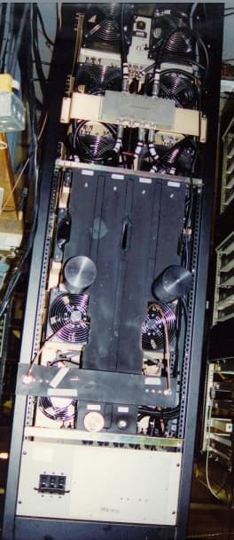
CJJ79XITS-7036
Mar 29, 2000MMDS/ITFS BROADBAND TRANSLATOR
Equipment Class
AMP - Amplifier