CLVAW2000Stereophonic Home Theater TX
Recoton Corporation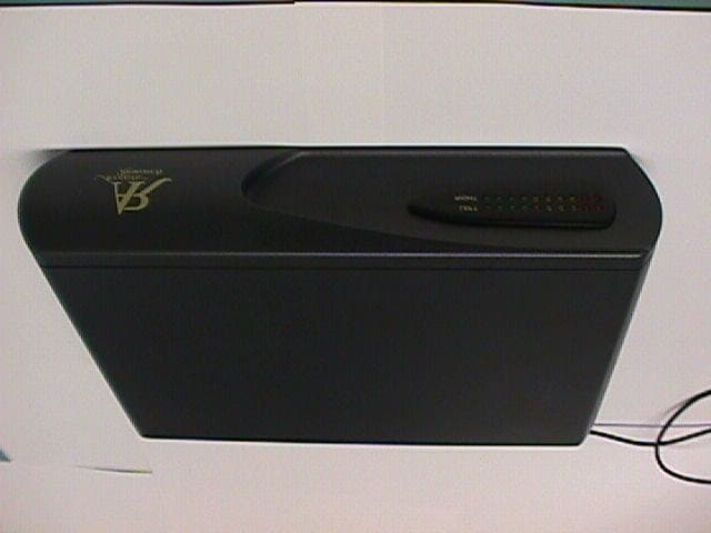
Click to zoom
Application Details
- Equipment Class
- DXX - Part 15 Low Power Communication Device Transmitter
- Date of Grant
- Jun 06, 2001
- Application Purpose
- Original Equipment
- Date of Application
- Jun 06, 2001
- Equipment Note
- Stereophonic Home Theater TX
- Frequency Range
- 2.28000000 - 2.79000000
- Company
- Recoton Corporation
- Country
- United States
Documents & Files
Document Text
Text extracted from the exhibit documents filed with the FCC. Open a document above to read the original.
Users Manual
Instruction Manual: AW2000 Magnetic Technology Rear Speaker 1.Connect transmitter to the sound source, using the supplied cable. 2. Connect the male connector of the transmitter box to the TV or VCR. 3. Connect the cable line, DSS downlead, or TV antenna to the female connector on the transmitter box. 4. Connect the power supply adaptor to the transmitter and plug it into a wall socket. The furnished power supply operates on standard U.S. 120Volt, 60 Hz AC. For other voltage applications, contact Recoton Customer Service at 800 RECOTON. 5. Move the power switch to the “on” position. 6. Adjust the modulation control until the modulation indicator shows the proper level. This will result in getting the clearest sound possible. 7. Locate the receiver battery compartment cover, and remove it. 8. Install 10 fresh “C” batteries in the compartment, giving careful attention to the polarity markings in the cabinet, and replace cover. 9. After selecting the spot that you desire the speaker to be used, mount the speaker on the wall, or place it on a table 10. Move the receiver power switch to the “on” position 11. If an audio source is present, advance the receiver “volume” control to the desired listening level. In case of difficulty: Verify that the wall socket that the transmitter power adaptor is plugged into is live. Plug a lamp into it to test. Verify that the receiver batteries are not discharged. Try a fresh set. This device complies with Part 15 of the FCC rules. Operation is subject to the following two conditions: (1) This device may not cause harmful interference, and (2) this device must accept any interference received, including interference that may cause undesired operation. User modification of this unit is a violation of FCC certification rules. There are no user serviceable components inside. Contact Recoton customer service at 800 RECOTON. Specifications: Transmitter Frequencies: 2.28 and 2.79 MHz Output power: Maximum allowed by FCC and Industry Canada regulation. Power Consumption: ____ W from 120V AC Audio input: ______to_______ Volts, RMS Receiver Receive frequencies: 2.28 and 2.79 MHz Audio output: ______ W RMS into Ω Frequency response: _____ to _________ Battery Life: _____ Hrs at 1 W output (Nominal. Recoton has no control over battery manufacturers quality and longevity.) RECOTON CORP. FCC ID: CLVAW2000 EXHIBIT #: 4
Cover Letter(s)
Recoton Corporation 2950 Lake Emma Rd Lake Mary, Fl 32714 May 1, 2001 Kenneth Nichols, Chief, Laboratory Division Office of Engineering and Technology Federal Communications Commission Columbia, MD 21046 Dear Mr. Nichols: Pursuant to Section 0.459 and 0.457(d)(ii), we are requesting that certain portions of this application be withheld from public inspection for 2 years. The materials to which this request applies have been separated physically and marked “CONFIDENTIAL, NOT FOR PUBLIC INSPECTION”. These materials consist of: Schematics, Theory of operation, Block diagrams, and Tuning Procedure. They contain trade secrets which are privileged, and for which patent protection has yet to be secured. Disclosure of these materials would do substantial harm to Recoton’s future business, and would deprive the public of a source of Magnetic Technology wireless audio devices. The material is not available to the public, and has been disclosed to third parties only pursuant to non-disclosure agreements of the type usually used in our industry. Protection for 2 years is required until the patent application can be files and processed. Please contact Jorgen Andersen, Chief Engineer at 407 833 1582 if there are any questions regarding this request. Regards, Jorgen Andersen, Chief Engineer RECOTON CORPORATION FCC ID: CLVAW2000 EXHIBIT #: 1
ID Label/Location Info
RECOTON CORP FCC ID: CLVAW2000 CANADA 123456789012 S/N 12123456789 This device complies with Part 15 of the FCC rules. Operation is subject to the following two conditions: (1) This device may not cause harmful interference; and (2) this device must accept any interference received, including interference that may cause undesired operation
Test Report
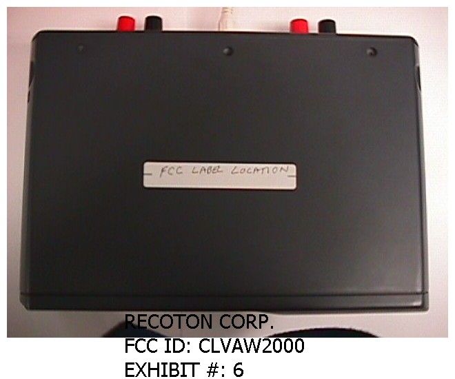
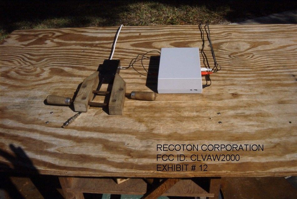
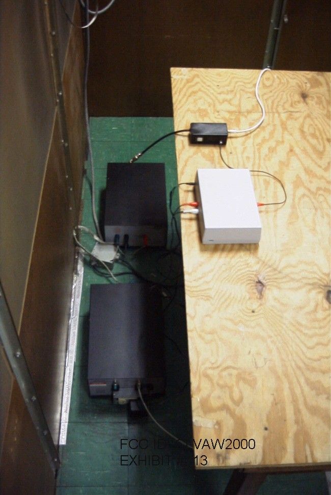
TABLE OF CONTENTS LIST APPLICANT: RECOTON CORPORATION FCC ID: CLVAW2000 TEST REPORT CONTAINING: PAGE 1.......TEST EQUIPMENT LIST AND TEST PROCEDURE PAGE 2.......TEST PROCEDURE CONTD. PAGE 3.......RADIATION INTERFERENCE TEST DATA PAGE 4.......OCCUPIED BANDWIDTH TEST DATA PAGE 5-7.....OCCUPIED BANDWIDTH PLOTS PAGE 8.......POWERLINE CONDUCTED TEST DATA PAGE 9-10....POWERLINE CONDUCTED PLOTS EXHIBITS CONTAINING: EXHIBIT 1............LETTER REQUESTING CONFIDENTIALITY EXHIBIT 2............BLOCK DIAGRAM EXHIBIT 3A-3B........SCHEMATICS EXHIBIT 4............INSTRUCTION MANUAL EXHIBIT 5............SAMPLE OF FCC ID LABEL EXHIBIT 6............LOCATION OF FCC ID LABEL EXHIBIT 7............EXTERNAL PHOTO - FRONT SIDE EXHIBIT 8............EXTERNAL PHOTO - BOTTOM SIDE EXHIBIT 9A...........INTERNAL PHOTO - COMPONENT SIDE – TOTAL VIEW EXHIBIT 9B...........INTERNAL PHOTO – COMPONENT SIDE – BOTTOM LEFT EXHIBIT 9C...........INTERNAL PHOTO – COMPONENT SIDE – MIDDLE LEFT EXHIBIT 9D...........INTERNAL PHOTO – COMPONENT SIDE – TOP LEFT EXHIBIT 9E...........INTERNAL PHOTO – COMPONENT SIDE –BOTTOM CENTER EXHIBIT 9F...........INTERNAL PHOTO – COMPONENT SIDE –MIDDLE CENTER EXHIBIT 9G...........INTERNAL PHOTO – COMPONENT SIDE –TOP CENTER EXHIBIT 9H...........INTERNAL PHOTO – COMPONENT SIDE –BOTTOM RIGHT EXHIBIT 9I...........INTERNAL PHOTO – COMPONENT SIDE –MIDDLE RIGHT EXHIBIT 9J...........INTERNAL PHOTO – COMPONENT SIDE –TOP RIGHT EXHIBIT 10...........INTERNAL PHOTO - COPPER SIDE EXHIBIT 11...........CIRCUIT DESCRIPTION EXHIBIT 12...........RADIATED TEST SET UP PHOTO EXHIBIT 13...........POWERLINE CONDUCTED TEST SET UP PHOTO APPLICANT: RECOTON CORPORATION FCC ID: CLVAW2000 REPORT #: T:\R\REC\373U1\373u1rpt.doc PAGE: TABLE OF CONTENTS LIST APPLICANT: RECOTON CORPORATION FCC ID: CLVAW2000 TEST EQUIPMENT LIST 1._X_Spectrum Analyzer: HP 8566B-Opt 462, S/N 3138A07786, w/ preselector HP 85685A, S/N 3221A01400, Quasi-Peak Adapter HP 8565OA, S/N 3303A01690 & Preamplifier HP 8449B-OPT H02, S/N 3008A00372 2._X_Biconnical Antenna: Eaton Model 94455-1, S/N 1057, 3.___Biconnical Antenna: Electro-Metrics Model BIA-25, S/N 1171 4._X_Log-Periodic Antenna: Electro-Metrics Model EM-6950, S/N 632 Cal. 5.___Log-Periodic Antenna: Electro-Metrics Model LPA-30, S/N 409 Cal. 6.___Double-Ridged Horn Antenna: Electro-Metrics Model RGA-180, 1-18 GHz, S/N 2319 7.___18-26.3GHz Systron Donner Standard Gain Horn #DBE-520-20 8.___Horn 40-60GHz: ATM Part #19-443-6R 9.___Line Impedance Stabilization Network: Electro-Metrics Model EM-7820, w/NEMA Adapter S/N 2682 10.___Temperature Chamber: Tenney Engineering Model TTRC, S/N 11717-7 11.___Frequency Counter: HP Model 5385A, S/N 3242A07460 12.___Peak Power Meter: HP Model 8900C, S/N 2131A00545, 13._X_Open Area Test Site #1-3meters Cal. 12/22/99 14.___Signal Generator: HP 8640B, S/N 2308A21464 15.___Signal Generator: HP 8614A, S/N 2015A07428 16.___Passive Loop Antenna: EMCO Model 6512, 9KHz to 30MHz, S/N 9706-1211 17.___Dipole Antenna Kit: Electro-Metrics Model TDA-30/1-4, S/N 153 18.___AC Voltmeter: HP Model 400FL, S/N 2213A14499 19.___Digital Multimeter: Fluke Model 8012A, S/N 4810047 20.___Digital Multimeter: Fluke Model 77, S/N 43850817 21.___Oscilloscope: Tektronix Model 2230, S/N 300572 TEST PROCEDURE GENERAL: This report shall NOT be reproduced except in full without the written approval of TIMCO ENGINEERING, INC. RADIATION INTERFERENCE: The test procedure used was ANSI STANDARD C63.4-1992 using a HEWLETT PACKARD spectrum analyzer with a prese- lector. The bandwidth of the spectrum analyzer was 100 kHz with an appropriate sweep speed. The analyzer was calibrated in dB above a microvolt at the output of the antenna. The resolution bandwidth was 100KHz and the video bandwidth was 300KHz. The ambient temperature of the UUT was 80oC with a humidity of 76%. APPLICANT: RECOTON CORPORATION FCC ID: CLVAW2000 REPORT #: T:\R\REC\373U1\373u1rpt.doc PAGE: 1 APPLICANT: RECOTON CORPORATION FCC ID: CLVAW2000 TEST PROCEDURES CONTINUED FORMULA OF CONVERSION FACTORS: The Field Strength at 3m was estab- lished by adding the meter reading of the spectrum analyzer (which is set to read in units of dBuV) to the antenna correction factor sup- plied by the antenna manufacturer. The antenna correction factors are stated in terms of dB. The gain of the Preselector was accounted for in the Spectrum Analyzer Meter Reading. Example: Freq (MHz) METER READING + ACF = FS 33 20 dBuV + 10.36 dB = 30.36 dBuV/m @ 3m POWER LINE CONDUCTED INTERFERENCE: The procedure used was ANSI STAN- DARD C63.4-1992 using a 50uH LISN. Both lines were observed. The bandwidth of the spectrum analyzer was 10kHz with an appropriate sweep speed. The ambient temperature of the UUT was 80oC with a humidity of 76%. ANSI STANDARD C63.4-1992 10.1.7 MEASUREMENT PROCEDURES: The unit under test was placed on a table 80 cm high and with dimensions of 1m by 1.5m. The table used for radiated measurements is capable of continuous rotation. When an emission was found, the table was rotated to produce the maximum signal strength. At this point, the antenna was raised and lowered from 1m to 4m. The antenna was placed in both the horizontal and vertical planes. The situation was similar for the conducted measurement except that the table did not rotate. The EUT was setup as described in ANSIC63.4-1992 with the EUT 40 cm from the vertical ground wall. APPLICANT: RECOTON CORPORATION FCC ID: CLVAW2000 REPORT #: T:\R\REC\373U1\373u1rpt.doc PAGE: 2 APPLICANT: RECOTON CORPORATION FCC ID: CLVAW2000 NAME OF TEST: RADIATION INTERFERENCE RULES PART NO.: 15.223 REQUIREMENTS: THE FIELD STRENGTH OF ANY EMISSION WITHIN THE BAND 1.705-10.0 MHz SHALL NOT EXCEED 100 uV/m (40 dBuV/m) at 30m. HOWEVER, IF THE BANDWIDTH OF THE EMISSION IS LESS THAN 10% OF THE CENTER FREQUENCY, THE FIELD STRENGTH SHALL NOT EXCEED 15 uV/m at 30m. OUT-OF-BAND EMISSIONS SHALL NOT EXCEED THE GENERAL RADIATED EMISSION LIMITINS IS 15.209. THE SPECTRUM WAS SEARCHED TO THE 10TH HARMONIC AND AND ONLY EMISSIONS LESS T…
Text truncated - open the document above for the full version.
Contact Information
Applicant
William McGreevy(Vice President, Engineering)
407 333-8900Fax: 407 333-8903
Test Firm
Timco Engineering, Inc.S Sanders
Technical Specifications
| # | Rule Parts | Frequency Range | Power Output |
|---|---|---|---|
| 1 | 15C | 2.28 MHz - 2.79 MHz | - |
Other Applications from Recoton Corporation
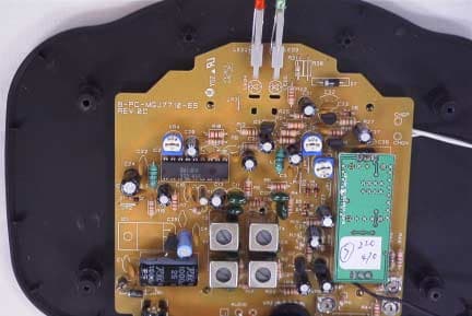
CLVAW771TX
Jul 10, 2003TRANSMITTER
Equipment Class
DXX - Part 15 Low Power Communication Device Transmitter
CLV-AW9T
Aug 14, 2002900 MHz Transmitter Module
Equipment Class
DXX - Part 15 Low Power Communication Device Transmitter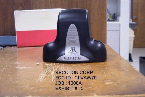
CLVAW791
Dec 06, 2001900 MHz Wireless Headphones
Equipment Class
DXX - Part 15 Low Power Communication Device Transmitter
CLV-RSN900
Sep 05, 2001900MHz Transmitter
Equipment Class
DXX - Part 15 Low Power Communication Device Transmitter
CLV-AP2000R
May 23, 2001Wireless Headphone Receiver
Equipment Class
CYY - Communications Receiver used w/Pt 15 Transmitter