CNTPP2080Wireless 2100 LAN 3A Mini PCI Adapter
HP Inc.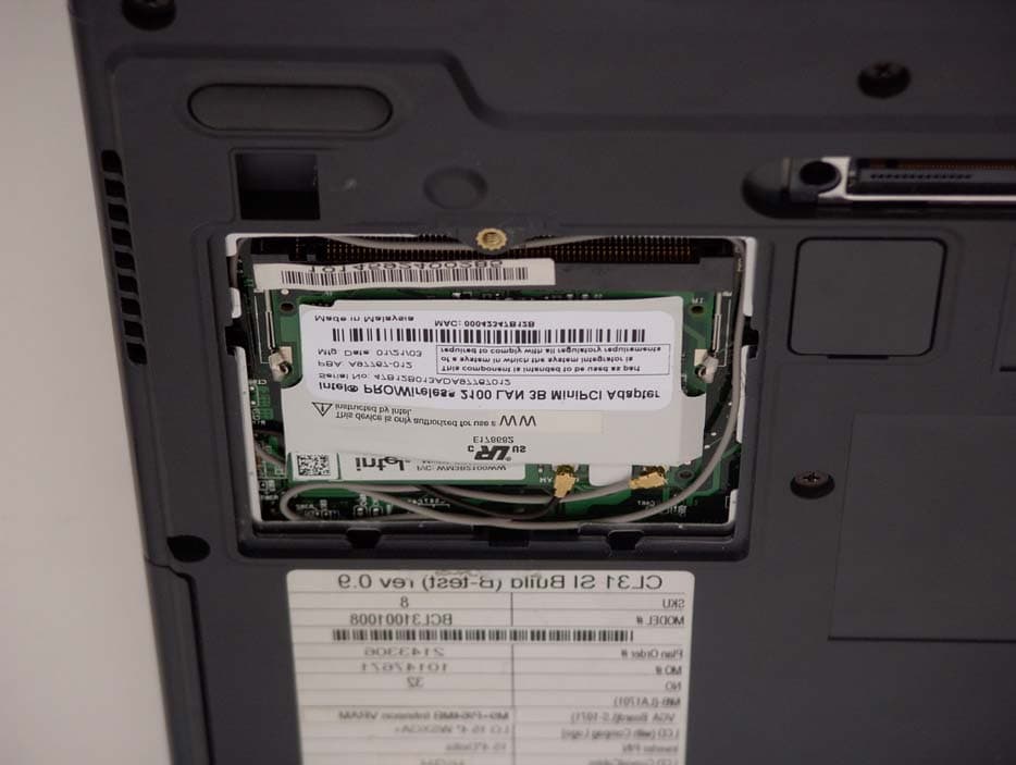
Click to zoom
Application Details
- Equipment Class
- DTS - Digital Transmission System
- Date of Grant
- Apr 30, 2003
- Application Purpose
- Original Equipment
- Date of Application
- Apr 30, 2003
- Equipment Note
- Wireless 2100 LAN 3A Mini PCI Adapter
- Frequency Range
- 2412.00000000 - 2462.00000000
- Company
- HP Inc.
- Country
- United States
Documents & Files
Document Text
Text extracted from the exhibit documents filed with the FCC. Open a document above to read the original.
Users Manual
Calexico Compliance Document Page 1 12/20/02 Mobile Communications Division Compliance Notices Source Document for OEMs Calexico Created: 09/25/02 Last Updated: 12/20/02TL Authors: Paul Straley, Tony Lukyn Calexico Compliance Document Page 2 12/20/02 Revision History Date Changes 09/25/02 Created document 10/03/02 Corrected errors in document, added 3 additional Mini PCI models, genericized product references to refer to “LAN Mini PCI Adapters” 10/08/02 Added Annex II under 1999/5/EC for 2.4 GHz products (PS) 12/18/02 Added “Information for the OEM” page 1 and additional text for OEM integrators page 4 (TL) 12/20/02 Added End Product Label: FCC ID “XXXXXXXX’ info. Calexico Compliance Document Page 3 12/20/02 Intel(R) PRO/Wireless LAN 7100 and 2100 Mini PCI Adapters Safety and Regulatory Notices Information for the OEM Integrators: Please refer to the full Grant of equipment document for other restrictions. Note: The following regulatory and safety notices must be published in compliance with local regulations. This information applies to the following products: Intel(R) PRO/Wireless LAN 7100 3B Mini PCI Adapter (model WM3B7100; dual 802.11a and 802.11b) Intel(R) PRO/Wireless LAN 7100 3A Mini PCI Adapter (model WM3A7100; dual 802.11a and 802.11b) Intel(R) PRO/Wireless LAN 2100 3B Mini PCI Adapter (model WM3B2100; 802.11b only) Intel(R) PRO/Wireless LAN 2100 3A Mini PCI Adapter (model WM3A2100; 802.11b only) Local Restriction of 802.11a and 802.11b Radio Usage The following statement on local restrictions must be published as part of the compliance documentation for all 802.11a and 802.11b products. Caution: Due to the fact that the frequencies used by 802.11a and 802.11b wireless LAN devices may not yet be harmonized in all countries, 802.11a and 802.11b products are designed for use only in specific countries, and are not allowed to be operated in countries other than those of designated use. As a user of these products, you are responsible for ensuring that the products are used only in the countries for which they were intended and for verifying that they are configured with the correct selection of frequency and channel for the country of use. Any deviation from permissible settings and restrictions in the country of use could be an infringement of national law and may be punished as such. USA and Canada Safety Requirements and Notices The FCC with its action in ET Docket 96-8 has adopted a safety standard for human exposure to radio frequency (RF) electromagnetic energy emitted by FCC certified equipment. The Intel PRO/Wireless LAN Mini PCI Adapter products meet the Human Exposure limits found in OET Bulletin 65, 2001, and ANSI/IEEE C95.1, 1992. Proper operation of this radio according to the instructions found in this manual will result in exposure substantially below the FCC’s recommended limits. The following safety precautions should be observed: • Do not touch or move antenna while the unit is transmitting or receiving. • Do not hold any component containing the radio such that the antenna is very close or touching any exposed parts of the body, especially the face or eyes, while transmitting. • Do not operate the radio or attempt to transmit data unless the antenna is connected; if not, the radio may be damaged. • Use in specific environments: o The use of wireless devices in hazardous locations is limited by the constraints posed by the safety directors of such environments. o The use of wireless devices on airplanes is governed by the Federal Aviation Administration (FAA). o The use of wireless devices in hospitals is restricted to the limits set forth by each hospital. • Antenna use: o In order to comply with FCC RF exposure limits, low gain integrated antennas should be located at a minimum distance of 20 cm (8 inches) or more from the body of all persons. o High-gain, wall-mount, or mast-mount antennas are designed to be professionally installed and should be located at a minimum distance of 30 cm (12 inches) or more from the body of all persons. Please contact your professional installer, VAR, or antenna manufacturer for proper installation requirements. Explosive Device Proximity Warning Warning: Do not operate a portable transmitter (such as a wireless network device) near unshielded blasting caps or in an explosive environment unless the device has been modified to be qualified for such use. Antenna Warning Warning: To comply with the FCC and ANSI C95.1 RF exposure limits, it is recommended for Intel(R) PRO/Wireless LAN Mini PCI Adapters installed in a desktop or portable computer, that the antenna for this device be installed so as to provide a separation distance of al least 20 cm (8 inches) from all persons and that the antenna must not be co-located or operating in conjunction with any other antenna or radio transmitter. It is recommended that the user limit exposure time if the antenna is positioned closer than 20 cm (8 inches). Use On Aircraft Caution Caution: Regulations of the FCC and FAA prohibit airborne operation of radio-frequency wireless devices because their signals could interfere with critical aircraft instruments. Other Wireless Devices Safety Notices for Other Devices in the Wireless Network: Refer to the documentation supplied with wireless Ethernet adapters or other devices in the wireless network. This device is intended for OEM integrators only. This device cannot be co-located with any other transmitter. Calexico Compliance Document Page 4 12/20/02 This device is intended only for OEM integrators under the following conditions: 1) The antenna must be installed such that 20 cm is maintained between the antenna and users. For laptop installations, the antenna must be installed to ensure that the proper spacing is maintained in the event the users places the device in their lap during use (i.e. positioning of antennas must be placed in the upper portion of the LCD panel only to ensure 20 cm will be maintained if the user places the device in their …
Text truncated - open the document above for the full version.
Users Manual
b Startup and Reference Guide Compaq Notebook Series Document Part Number: 311245-001 June 2003 Part 1 Startup The Startup section of this guide explains how to set up your notebook for the first time. Part 2 Reference The Reference section of this guide explains how to identify and use the hardware and software features on your notebook. CPQ-311245-001.book Page i Thursday, March 27, 2003 10:17 PM Contents 1Startup 2 Hardware 3 Keyboard 4Power 5 Drives and Drive Media 6 Multimedia 7 Communications 8 Hardware Options and Upgrades 9 Software Updates, Restorations and Utilities A Specifications Index CPQ-311245-001.book Page ii Thursday, March 27, 2003 10:17 PM Startup and Reference Guide—Part 11–1 Part-1 Startup This Startup and Reference Guide provides information about setting up and using your notebook. ■To set up your notebook hardware and software for the first time, follow the procedures in this “Startup” section. ■To learn more about using your notebook, refer to the remaining sections of this book. To find information about a specific topic: ❏Refer to the chapter Contents on the first page of each chapter, or ❏Consult the Index. CPQ-311245-001.book Page 1 Thursday, March 27, 2003 10:17 PM 1–2Startup and Reference Guide—Part 1 Startup Setting Up the Hardware To set up the notebook for the first time, you need the notebook, the AC adapter 1, the power cord 2, and the battery pack3. During hardware setup, you will: ■Insert the battery pack into the notebook, so the battery can begin to charge as soon as the notebook is connected to external power. ■Open the notebook. ■Connect the notebook to external power and turn on the notebook. You will then proceed to software setup. Identifying the AC adapter, the power cord, and the battery pack (Power cords vary by region and country.) CPQ-311245-001.book Page 2 Thursday, March 27, 2003 10:17 PM Startup Startup and Reference Guide—Part 11–3 Inserting a Battery Pack To insert the battery pack into the battery bay: 1. Turn the notebook underside up on a flat surface. 2. Insert the alignment tab on the battery pack into the alignment slot on the notebook 1. 3. Tilt the battery pack downward until it snaps into place 2. Inserting a battery pack Ä CAUTION: To ensure that the correct drivers load and to prevent file corruption or damage to components, do not remove the battery pack until the notebook has been connected to external AC power. CPQ-311245-001.book Page 3 Thursday, March 27, 2003 10:17 PM 1–4Startup and Reference Guide—Part 1 Startup Opening the Notebook To open the notebook: 1. Place the notebook display side up on a flat surface near an electrical outlet. 2. Slide the display release latch1 as you raise the display2. Opening the notebook CPQ-311245-001.book Page 4 Thursday, March 27, 2003 10:17 PM Startup Startup and Reference Guide—Part 11–5 Connecting the Notebook to External Power To connect the notebook to external AC power: 1. Plug the AC adapter cable into the power connector 1. 2. Plug the power cord into the AC adapter 2, then into an electrical outlet 3. When the notebook is receiving external power, the battery light4 turns on. Connecting the notebook to external power (Power cords and outlets vary by region and country.) CPQ-311245-001.book Page 5 Thursday, March 27, 2003 10:17 PM 1–6Startup and Reference Guide—Part 1 Startup Charging a New Battery Pack The battery pack you inserted earlier begins to charge as soon as the notebook is connected to external power. Charge status is indicated by the battery light. ■The battery light is on and amber while a battery pack inserted into the notebook is charging. ■The battery light is on and green when a battery pack inserted into the notebook is fully charged. Compaq recommends that you leave the notebook connected to external power until the battery pack is fully charged and the battery light turns green. (A partially charged new battery pack can run the notebook after initial software setup is complete, but battery charge displays will not be accurate until the new battery pack has been fully charged.) Identifying the battery light CPQ-311245-001.book Page 6 Thursday, March 27, 2003 10:17 PM Startup Startup and Reference Guide—Part 11–7 Turning On the Notebook To turn on the notebook, press the power button1. When the notebook turns on, the power/standby light2 turns on, and you are prompted to begin software setup. Turning on the notebook If the notebook does not turn on: ■Make sure that the AC adapter is securely plugged into an electrical outlet. ■Make sure that the outlet is providing power. (To confirm that the outlet is providing power, plug another device into the outlet.) ■If you have installed a battery pack, make sure that the battery pack is firmly seated. ■Refer to the Worldwide Telephone Numbers booklet (English only) included with the notebook to contact a Compaq authorized dealer, reseller, or service provider. CPQ-311245-001.book Page 7 Thursday, March 27, 2003 10:17 PM 1–8Startup and Reference Guide—Part 1 Startup Setting Up the Software Installing Basic Software When the notebook is connected to external power and turned on for the first time, a prompt to set up the operating system and other basic software is displayed on the screen. Before responding to the prompt and proceeding through the on-screen instructions, read the following caution and other installation information. Ä CAUTION: To prevent file corruption and ensure that the correct drivers are installed, install software only when the notebook is connected to external power through the AC adapter. During the installation: ■Do not unplug the notebook from external power. ■Do not shut down the notebook or initiate Standby or Hibernation. ■Do not insert, remove, connect, or disconnect any device, cable, or cord. ■After beginning the software setup, you must complete the entire process without interruption. Setup time varies. ■If you are prompted to select a language, choose carefully. On some models, the…
Text truncated - open the document above for the full version.
Users Manual
Startup and Reference Guide—Part 22–1 2 Hardware Contents Display . . . . . . . . . . . . . . . . . . . . . . . . . . . . . . . . . . . . . . . 2–2 Top . . . . . . . . . . . . . . . . . . . . . . . . . . . . . . . . . . . . . . . . . . 2–3 TouchPad . . . . . . . . . . . . . . . . . . . . . . . . . . . . . . . . . . 2–3 Keys and Antenna . . . . . . . . . . . . . . . . . . . . . . . . . . . 2–4 Power Controls . . . . . . . . . . . . . . . . . . . . . . . . . . . . . 2–5 Lights . . . . . . . . . . . . . . . . . . . . . . . . . . . . . . . . . . . . . 2–6 Audio Buttons and Speakers . . . . . . . . . . . . . . . . . . . 2–7 Front Panel . . . . . . . . . . . . . . . . . . . . . . . . . . . . . . . . . . . . 2–8 Rear Panel . . . . . . . . . . . . . . . . . . . . . . . . . . . . . . . . . . . . 2–9 Connectors and Jacks. . . . . . . . . . . . . . . . . . . . . . . . . 2–9 Vent . . . . . . . . . . . . . . . . . . . . . . . . . . . . . . . . . . . . . 2–10 Left Side . . . . . . . . . . . . . . . . . . . . . . . . . . . . . . . . . . . . . 2–11 Right Side. . . . . . . . . . . . . . . . . . . . . . . . . . . . . . . . . . . . 2–12 Underside . . . . . . . . . . . . . . . . . . . . . . . . . . . . . . . . . . . . 2–13 Bays and Memory Compartment. . . . . . . . . . . . . . . 2–13 Docking Connector and Vents. . . . . . . . . . . . . . . . . 2–14 Labels. . . . . . . . . . . . . . . . . . . . . . . . . . . . . . . . . . . . 2–15 Additional Standard Components . . . . . . . . . . . . . . . . . 2–16 Cables and Cord. . . . . . . . . . . . . . . . . . . . . . . . . . . . 2–16 Adapters and Battery Pack . . . . . . . . . . . . . . . . . . . 2–17 Restoration and Documentation CDs . . . . . . . . . . . 2–18 CPQ-311245-001.book Page 1 Thursday, March 27, 2003 10:17 PM 2–2Startup and Reference Guide—Part 2 Hardware Display Display Display release latchOpens the notebook. CPQ-311245-001.book Page 2 Thursday, March 27, 2003 10:17 PM Hardware Startup and Reference Guide—Part 22–3 Top TouchPad Top: TouchPad 1 TouchPad on/off buttonEnables/disables the TouchPad. 2 TouchPad*Moves the pointer and selects or activates items on the screen. 3 TouchPad lightOn: TouchPad is enabled. 4 TouchPad scroll zones (2)*Scroll upward or downward. 5 Left and right TouchPad buttons*Function like the left and right buttons on an external mouse. *This table describes default settings. For information about changing the functions of TouchPad features, see “Setting TouchPad Preferences” in Chapter 3. CPQ-311245-001.book Page 3 Thursday, March 27, 2003 10:17 PM 2–4Startup and Reference Guide—Part 2 Hardware Keys and Antenna Top: Keys and Antenna 1 Fn keyCombines with other keys to perform system tasks. For example, pressing Fn+F7 increases screen brightness. 2 Function keys (12)Perform system and application tasks. When combined with the Fnkey, the function keys F1 and F3 through F12 perform additional tasks as hotkeys. 3 Keypad keys (15)*Can be used like the keys on an external numeric keypad. 4 Applications keyDisplays a shortcut menu for items beneath the pointer. 5 Antenna (available on select models and not visible from outside the notebook)* Sends and receives wireless device signals. 6 Microsoft logo keyDisplays the Windows Start menu. *The notebook has 2 antennas. The second is on the right side of the notebook. For optimal transmissions, keep the areas immediately over the antennas free from obstructions. CPQ-311245-001.book Page 4 Thursday, March 27, 2003 10:17 PM Hardware Startup and Reference Guide—Part 22–5 Power Controls Top: Power Controls 1 Power button*When the notebook is: ■Off, press to turn on the notebook. ■On, briefly press to initiate Hibernation. ■In Standby, briefly press to resume from Standby. ■In Hibernation, briefly press to restore from Hibernation. ✎ If the system has stopped responding and Windows shutdown procedures cannot be used, press and hold for at least 4 seconds to turn off the notebook. 2 Display switch* ■If the notebook is closed while on, turns off the display. ■If the notebook is opened while in Standby, turns on the notebook (resumes from Standby). *This table describes default settings. For information about changing the function of the power button or display switch, see “Setting Power Control Preferences” in Chapter 4. CPQ-311245-001.book Page 5 Thursday, March 27, 2003 10:17 PM 2–6Startup and Reference Guide—Part 2 Hardware Lights Top: Lights 1 Num lock lightOn: Num lock or the internal keypad is on. 2 Caps lock lightOn: Caps lock is on. 3 Mute lightOn: Volume is muted. 4 Wireless device light (available on select models) On: An optional internal wireless device is turned on. 5 Battery lightOn: The notebook is receiving adequate external power. ■On amber: A battery pack is charging. ■On green: A battery pack is fully charged. ■Flashing: A battery pack is malfunctioning and may need to be replaced. 6 IDE (Integrated Drive Electronics) drive light On: The internal hard drive or optical drive is being accessed. 7 Power/standby lightOn: Notebook is turned on. Flashing: Notebook is in Standby. CPQ-311245-001.book Page 6 Thursday, March 27, 2003 10:17 PM Hardware Startup and Reference Guide—Part 22–7 Audio Buttons and Speakers Top: Audio Buttons and Speakers 1 Increase volume buttonIncreases system volume. 2 Decrease volume buttonDecreases system volume. 3 Mute buttonMutes or restores volume. 4 Stereo speakers (2)Produce stereo sound. CPQ-311245-001.book Page 7 Thursday, March 27, 2003 10:17 PM 2–8Startup and Reference Guide—Part 2 Hardware Front Panel Front Panel 1 SD (Secure Digital) Card slotSupports SD Cards and MMCs (multimedia cards). 2 SD Card lightOn: An SD Card or MMC is being accessed. 3 Microphone jackConnects an optional monaural or stereo microphone. 4 Audio-out jackConnects optional headphones or powered stereo speakers. Also connects the audio function of an audio/video device such as a television or VCR. 5 Wireless device button (available on select models) Turns an optional internal wi…
Text truncated - open the document above for the full version.
Users Manual
Startup and Reference Guide—Part 24–1 4 Power Contents Understanding Standby, Hibernation and Shutdown . . . . 4–2 Standby . . . . . . . . . . . . . . . . . . . . . . . . . . . . . . . . . . . 4–2 Hibernation . . . . . . . . . . . . . . . . . . . . . . . . . . . . . . . . 4–2 Shutdown . . . . . . . . . . . . . . . . . . . . . . . . . . . . . . . . . . 4–3 Choosing Standby, Hibernation or Shutdown . . . . . . . . . 4–4 Using Standby, Hibernation and Shutdown Procedures . . . . . . . . . . . . . . . . . . . . . . . . . . . . . . . . . . . . 4–5 Identifying Power Controls and Indicators . . . . . . . . 4–5 Turning the Notebook or Display On or Off . . . . . . . 4–6 Using Emergency Shutdown Procedures . . . . . . . . . 4–6 Initiating or Resuming from Standby . . . . . . . . . . . . 4–7 Initiating or Restoring from Hibernation. . . . . . . . . . 4–8 Setting Power Control Preferences . . . . . . . . . . . . . . . . . 4–9 Using a Battery Pack . . . . . . . . . . . . . . . . . . . . . . . . . . . 4–10 Identifying the Battery and Power/Standby Lights . . . . . . . . . . . . . . . . . . . . . . . . . . . . . . . . . . . . 4–10 Switching Between Battery and External Power . . . . . . . . . . . . . . . . . . . . . . . . . . . . . . . . . . . . 4–11 Charging a Battery Pack . . . . . . . . . . . . . . . . . . . . . 4–11 Monitoring the Charge in a Battery Pack . . . . . . . . 4–12 Managing Low-Battery Conditions . . . . . . . . . . . . . 4–13 Calibrating a Battery Pack . . . . . . . . . . . . . . . . . . . . 4–14 Storing a Battery Pack . . . . . . . . . . . . . . . . . . . . . . . 4–16 Battery Conservation Settings and Procedures . . . . 4–17 Replacing a Battery Pack . . . . . . . . . . . . . . . . . . . . . . . . 4–18 CPQ-311245-001.book Page 1 Thursday, March 27, 2003 10:17 PM 4–2Startup and Reference Guide—Part 2 Power Recycling or Disposing of a Used Battery Pack . . . . . . 4–19 Understanding Standby, Hibernation and Shutdown This section describes Standby, Hibernation, and shutdown and explains when to implement them. Standby, Hibernation, and shutdown procedures are provided later in the chapter. Standby and Hibernation are energy-saving features that can be initiated by you or by the system. Standby Standby reduces power to system components that are not in use. When Standby is initiated, your work is saved in random access memory (RAM) and the screen is cleared. ■Saving your work before initiating Standby is not usually necessary, but is a recommended precaution. ■When the notebook is in Standby, the power/standby light flashes. When you resume from Standby, your work returns to the screen where you left off. Hibernation Hibernation saves system memory to the hard drive, takes a snapshot of the notebook image, then shuts down the notebook. When you resume from Hibernation, your work returns to the screen exactly as you left it. The following information may be useful as you manage Hibernation: ■Saving your work before initiating Hibernation is not usually necessary, but is a recommended precaution. CPQ-311245-001.book Page 2 Thursday, March 27, 2003 10:17 PM Power Startup and Reference Guide—Part 24–3 ■To determine whether the notebook is in Hibernation or turned off, press the power button: ❏If the notebook is in Hibernation, your work returns to the screen. ❏If the notebook is off, Windows loads. ■Hibernation is enabled by default, but can be disabled. To prevent loss of work during a critical low-battery condition, disable Hibernation only during a battery pack calibration. To verify that Hibernation is enabled, select Start > Control Panel > Performance and Maintenance > Power Options icon > Hibernate tab. If Hibernation is enabled, the Enable Hibernation check box is selected. Ä CAUTION: If the configuration of the notebook system is changed during Hibernation, it may not be possible to resume from Hibernation. When the notebook is in Hibernation: ■Do not add or remove a memory module. ■Do not connect or disconnect an external device. ■Do not insert or remove a CD, DVD, PC Card, SD Card, or MMC. Shutdown Shutdown procedures turn off the notebook. Whether to leave a battery pack in the notebook or in storage depends on how you work: ■Leaving the battery pack in the notebook enables the battery pack to charge whenever the notebook is connected to external power and also protects your work during a power outage. ■A battery pack in the notebook discharges more quickly, even when the notebook is turned off, than a battery pack that has been removed from the notebook and stored in a cool, dry location. CPQ-311245-001.book Page 3 Thursday, March 27, 2003 10:17 PM 4–4Startup and Reference Guide—Part 2 Power Choosing Standby, Hibernation or Shutdown If you plan to resume shortly: Initiate Standby for shorter times and Hibernation for longer times or power conservation. The amount of time a battery pack can support Standby or Hibernation or hold a charge varies by notebook configuration and the condition of the battery pack. ■Initiating Standby clears the screen, uses less power than leaving the notebook on, and your work returns quickly to the screen when you resume from Standby. A fully charged new battery pack can typically support Standby for up to 48 hours. ■Initiating Hibernation clears the screen and uses much less power than Standby. Returning to work saved in Hibernation takes longer than returning to work saved in Standby, but is faster than returning to your place manually after restarting the notebook. A fully charged new battery pack can typically support Hibernation for several weeks. If you plan to resume within 2 weeks: Shut down the notebook. If possible, connect the notebook to external power to keep an inserted battery pack fully charged. If the notebook will be disconnected from external power for more than 2 weeks: To extend the life of an inserted battery pack, shut down the notebook. Remove the battery pack and store it in a cool, dry location. If an external power supply is …
Text truncated - open the document above for the full version.
Users Manual
Startup and Reference Guide—Part 26–1 6 Multimedia Contents Adjusting Volume . . . . . . . . . . . . . . . . . . . . . . . . . . . . . . 6–2 Using the Internal Speakers . . . . . . . . . . . . . . . . . . . . . . . 6–3 Connecting an Audio Device . . . . . . . . . . . . . . . . . . . . . . 6–4 Connecting an S-Video Device . . . . . . . . . . . . . . . . . . . . 6–5 Connecting the Audio . . . . . . . . . . . . . . . . . . . . . . . . 6–5 Connecting the Video . . . . . . . . . . . . . . . . . . . . . . . . 6–5 Turning a Video Device On and Off . . . . . . . . . . . . . 6–6 Changing the Color Television Format . . . . . . . . . . . 6–6 Using Multimedia Software . . . . . . . . . . . . . . . . . . . . . . . 6–7 Using Windows Media Player . . . . . . . . . . . . . . . . . . 6–7 Using WinDVD . . . . . . . . . . . . . . . . . . . . . . . . . . . . . 6–7 Using Easy CD Creator . . . . . . . . . . . . . . . . . . . . . . . 6–9 CPQ-311245-001.book Page 1 Thursday, March 27, 2003 10:17 PM 6–2Startup and Reference Guide—Part 2 Multimedia Adjusting Volume Volume can be adjusted by using the audio buttons on the notebook or by using operating system or application volume control software. The mute button overrides all software volume settings. To adjust volume using the audio buttons: ■To increase volume, press the increase volume button 1. ■To decrease volume, press the decrease volume button 2. ■To mute or restore volume, press the mute button 3. When volume is muted, the mute light 4 turns on. When volume is restored, the mute light turns off. Identifying the audio buttons and mute light CPQ-311245-001.book Page 2 Thursday, March 27, 2003 10:17 PM Multimedia Startup and Reference Guide—Part 26–3 Using the Internal Speakers The internal speakers play sound in stereo from applications, the operating system, games, drive media, the Internet, and other sources. If an external device, such as a headset, is connected to the audio-out jack, the internal speakers are disabled. Identifying the internal speakers CPQ-311245-001.book Page 3 Thursday, March 27, 2003 10:17 PM 6–4Startup and Reference Guide—Part 2 Multimedia Connecting an Audio Device Å WARNING: To reduce the risk of personal injury, adjust the volume before putting on headphones or a headset. Ä CAUTION: To prevent possible damage to an external device, do not plug a monaural (single sound channel) plug into the audio-out jack. The notebook has 2 audio jacks: ■The microphone jack 1 connects an optional monaural or stereo microphone. If a monaural microphone is connected, the same information is recorded on both channels. ■The audio-out jack 2, sometimes called a line-out jack, connects headphones or powered external stereo speakers. The audio-out jack is also used to connect the audio functions of an audio/video device such as a television or VCR. When you connect a device to the audio-out jack: ❏Use only a 3.5-mm plug. ❏The internal speakers are disabled. Identifying the audio jacks CPQ-311245-001.book Page 4 Thursday, March 27, 2003 10:17 PM Multimedia Startup and Reference Guide—Part 26–5 Connecting an S-Video Device Connecting the Audio The S-Video jack supports video signals only. If you are setting up a configuration that combines audio and video functions, such as playing a DVD movie on your notebook and displaying it on your television, you will need a standard 3.5-mm audio cable available from most computer or electronics retailers. Plug the stereo end of the audio cable into the notebook audio-out jack. Plug the other end of the cable into the audio input jack on the external device. Connecting the Video To transmit video signals through the S-Video jack, you will need a standard S-Video cable available from most computer or electronics retailers. Plug either end of the S-Video cable into the notebook S-Video jack. Plug the other end of the cable into the S-Video input jack on the external device. Identifying the S-Video jack CPQ-311245-001.book Page 5 Thursday, March 27, 2003 10:17 PM 6–6Startup and Reference Guide—Part 2 Multimedia Turning a Video Device On and Off To turn on a video device that is connected to the notebook, start or restart the notebook. Or, repeatedly press the Fn+F4 hotkeys to switch the image. Pressing the Fn+F4 hotkeys switches the image among the notebook display, any connected displays, and simultaneous display on the notebook and all connected displays. ■Switching the image to a connected video device turns on the video device. ■Switching the image to the notebook display only turns off the video device. Changing the Color Television Format Color television formats are modes by which television video signals are sent and received. To send signals between the notebook and a television, both the notebook and the television must be using the same color television format. The NTSC format is common in the United States, Canada, Japan, and South Korea. The PAL format is common in Europe, China, Russia, and Africa, and the PAL-M format is common in Brazil. Other South American and Central American countries may use NTSC, PAL, or PAL-M. Region-specific formats are set at the factory for most notebooks, but the region setting can be changed on any notebook. Color television format settings are changed in the Setup utility. The Setup utility is not a Windows utility and does not support the TouchPad. For information about using the Setup utility, see the “Using the Setup Utility” section in Chapter 9. CPQ-311245-001.book Page 6 Thursday, March 27, 2003 10:17 PM Multimedia Startup and Reference Guide—Part 26–7 Using Multimedia Software Using Windows Media Player Use Windows Media Player primarily for playing audio CDs. Although video CDs can be played using Windows Media Player, InterVideo WinDVD provides higher quality playback. To open Windows Media Player, insert a CD into the optical drive, then close the tray. Wait several seconds. If Windows Media Player does not open, select Start > All Programs > Windows Media Play…
Text truncated - open the document above for the full version.
Contact Information
Applicant
Richard P Tarsio(US Canada Technical Regulations)
Technical Contact
Aegis Labs, Inc.Rick Candelas
[email protected]949-459-7886
22431-B160 Antonio Parkway #417 · Rancho Santa Margarita, California · United States
Test Firm
Aegis Labs, Inc.Rick Candelas
Technical Specifications
| # | Rule Parts | Frequency Range | Power Output |
|---|---|---|---|
| 1 | 15C | 2.41 GHz - 2.46 GHz | 48.00 mW |
Other Applications from HP Inc.
CNTBOISB110600
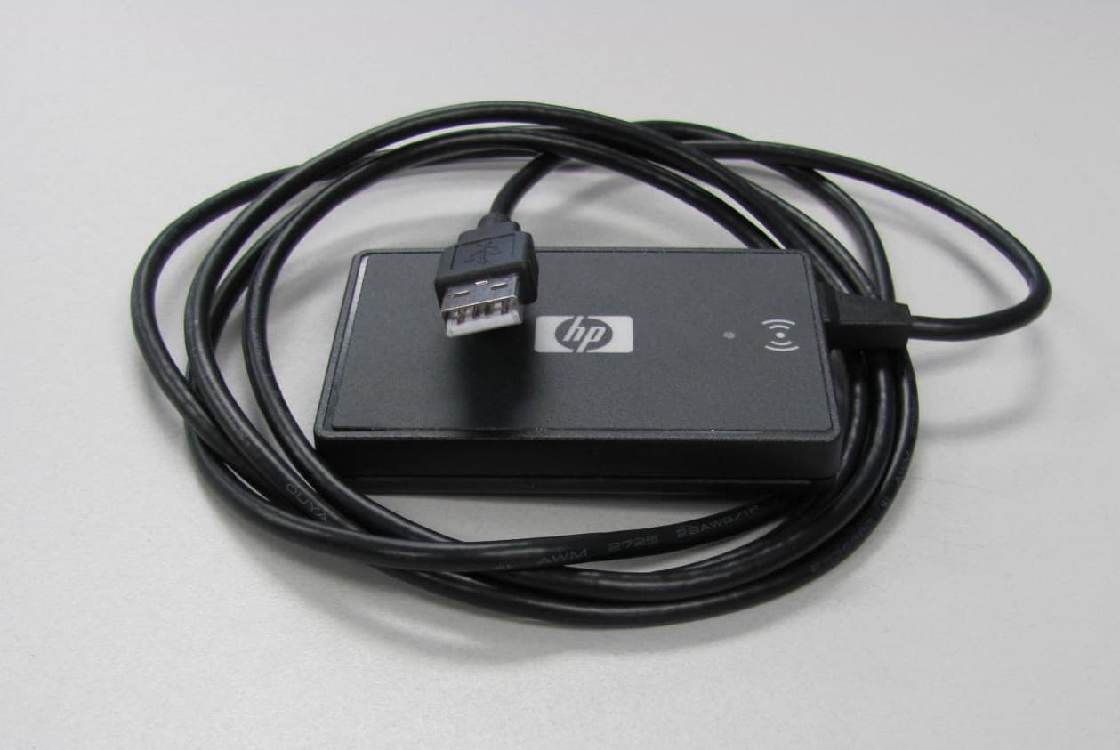
Jul 17, 2011Multi-Protocol RFID Reader
Equipment Class
DXX - Part 15 Low Power Communication Device Transmitter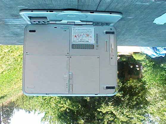
CNTWM3B2915ABG
Dec 19, 2004Intel Mini PCI Type 802.11ABG WLAN Adapter
Equipment Class
NII - Unlicensed National Information Infrastructure TX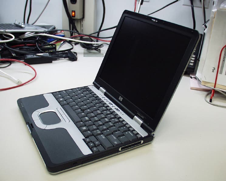
CNTPP2170SIL
Apr 08, 2004Laptop with WLAN and Bluetooth
Equipment Class
DTS - Digital Transmission System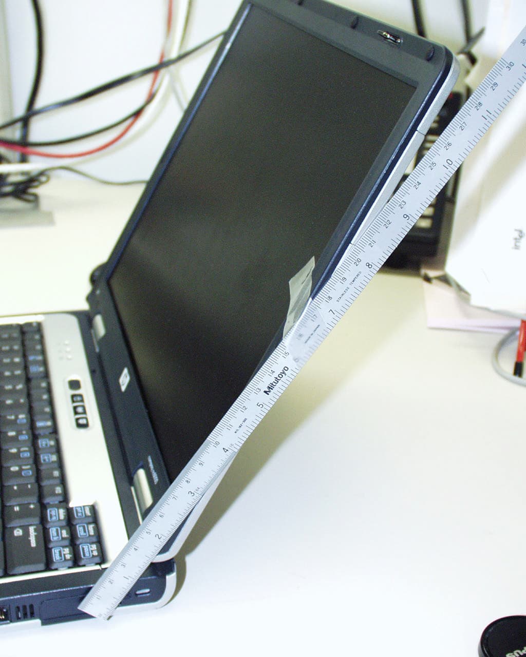
CNTWM3B2200BGA
Feb 29, 2004Laptop w/ Intel 802.11 BG Wireless LAN Adapter
Equipment Class
DTS - Digital Transmission System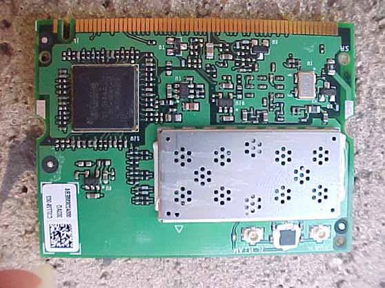
CNTHSTNN-I01C
Nov 13, 2003Notebook PC with Built-in Wireless
Equipment Class
DTS - Digital Transmission System