CNTPP2170Notebook PC with Built-in Wireless
HP Inc.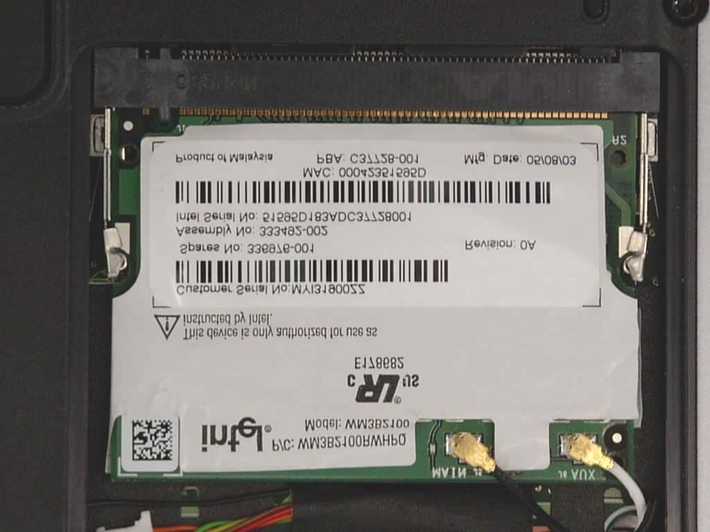
Click to zoom
Application Details
- Equipment Class
- DSS - Part 15 Spread Spectrum Transmitter
- Date of Grant
- Sep 11, 2003
- Application Purpose
- Original Equipment
- Date of Application
- Sep 11, 2003
- Equipment Note
- Notebook PC with Built-in Wireless
- Frequency Range
- 2412.00000000 - 2462.00000000
- Company
- HP Inc.
- Country
- United States
Documents & Files
Document Text
Text extracted from the exhibit documents filed with the FCC. Open a document above to read the original.
Users Manual
Intel(R) PRO/Wireless LAN Mini PCI Adapter User's Guide This document provides information for the following wireless devices: l Intel(R) PRO/Wireless LAN 7100 3B Mini PCI Adapter, operating at 5 GHz l Intel(R) PRO/Wireless LAN 2100 3B Mini PCI Adapter, operating at 2.4 GHz These wireless adapters operate with high-capacity networks using multiple access points within large or small environments. Using the Intel(R) PROSet Windows utility you can configure, manage wireless local area network (WLAN) management tasks, adapter switching functions, and connections. Wireless LAN General Information About Wireless LAN Technology Administrator's Guide Adapter Setup and Configuration Software Installation Using PROSet Connecting to a Network Security Overview Setting Up Security Troubleshooting Specifications Glossary Support and Warranty Customer Support Software License Safety and Regulatory Notices Limited Warranty Adapter Registration Legal Notices Copyright © 2002 Intel Corporation. All rights reserved. Intel Corporation, 5200 N.E. Elam Young Parkway, Hillsboro, OR 97124-6497 Intel Corporation assumes no responsibility for errors or omissions in this document. Nor does Intel make any commitment to update the information contained herein. Intel, Itanium, and Pentium are trademarks or registered trademarks of Intel Corporation or its subsidiaries in the United States and other countries. *Other names and brands may be claimed as the property of others. Back to Contents Page About Wireless LAN Technology l Choosing a WLAN l Configuring a WLAN l Identifying a WLAN l Surveying the Site of Your WLAN l Factors Affecting Range l Stronger Security A wireless network connects computers without using network cables. Computers use radio communications to send data between each other. You can communicate directly with other wireless computers, or connect to an existing network through a wireless access point. When you set up your wireless adapter, you select the operating mode for the kind of wireless network you want. You can use your Intel(R) PRO/Wireless adapter to connect to other similar wireless devices that comply with the 802.11 standard for wireless networking. Choosing a Wireless LAN Mode Wireless LANs can operate with or without access points, depending on the number of users in the network. Infrastructure mode uses access points to allow wireless computers to send and receive information. Wireless computers transmit to the access point, the access point receives the information and rebroadcasts it to other computers. The access point can also connect to a wired network or to the Internet. Multiple access points can work together to provide coverage over a wide area. Peer-to-Peer mode, also called Ad Hoc mode, works without access points and allows wireless computers to send information directly to other wireless computers. You can use Peer-to-Peer mode to network computers in a home or small office or to set up a temporary wireless network for a meeting. Configuring a Wireless LAN There are three basic components that must be configured for a wireless LAN to operate properly: l Network Name—Each wireless network uses a unique Network Name to identify the network. This name is called the Service Set Identifier (SSID). When you set up your wireless adapter, you specify the SSID. If you want to connect to an existing network, you must use the name for that network. If you are setting up your own network you can make up your own name and use it on each computer. The name can be up to 32 characters long and contain letters and numbers. l Profiles—When you set up your computer to access a wireless network, Intel(R) PROSet creates a profile for the wireless settings that you specify. If you want to connect to another network, you can scan for existing networks and make a temporary connection, or create a new profile for that network. After you create profiles, your computer will automatically connect when you change locations. l Security—The 802.11 wireless networks use encryption to help protect your data. Wired equivalent privacy (WEP) uses a 64-bit or 128-bit shared encryption key to scramble data. Before a computer transmits data, it scrambles the data using the secret encryption key. The receiving computer uses this same key to unscramble the data. If you are connecting to an existing network, use the encryption key provided by the administrator of the wireless network. If you are setting up your own network you can make up your own key and use it on each computer. Identifying a Wireless Network Depending on the size and components of a wireless LAN, there are many ways to identify a wireless LAN: l The Network Name or Service Set Identifier (SSID)—Identifies a wireless network. All wireless devices on the network must use the same SSID. l Extended Service Set Identifier (ESSID)—A special case of SSID used to identify a wireless network that includes access points. l Independent Basic Service Set Identifier (IBSSID)—A special case of SSID used to identify a network of wireless computers configured to communicate directly with one another without using an access point. l Basic Service Set Identifier (BSSID)—A unique identifier for each wireless device. The BSSID is the Ethernet MAC address of the device. l Broadcast SSID—An access point can respond to computers sending probe packets with the broadcast SSID. If this feature is enabled on the access point, any wireless user can associate with the access point by using a blank (null) SSID. Surveying the Site of Your Wireless LAN Conducting a site survey for your wireless LAN is the most crucial step in the process of setting up a wireless network. It greatly reduces the amount of troubleshooting you will have to do once you have the wireless LAN set up and ready for connection testing. To conduct a site survey, you will need the following tools: l An access point (or laptop computer) that is set up to be the transmitter. It should be mounted near a…
Text truncated - open the document above for the full version.
Users Manual
Hardware Guide hp compaq notebook series Document Part Number: 309971-001 April 2003 This guide explains how to identify and use notebook hardware features, including connectors for external devices. It also includes power and environmental specifications, which may be helpful when traveling with the notebook. © 2003 Hewlett-Packard Company Microsoft and Windows are trademarks of Microsoft Corporation in the U.S. and/or other countries. Intel and SpeedStep are trademarks of Intel Corporation in the U.S. and/or other countries. SD Logo is a trademark. HP shall not be liable for technical or editorial errors or omissions contained herein or for incidental or consequential damages in connection with the furnishing, performance, or use of this material. The information in this document is provided “as is” without warranty of any kind, including, but not limited to, the implied warranties of merchantability and fitness for a particular purpose, and is subject to change without notice. The warranties for HP products are set forth in the express limited warranty statements accompanying such products. Nothing herein should be construed as constituting an additional warranty. This document contains proprietary information that is protected by copyright. No part of this document may be photocopied, reproduced, or translated to another language without the prior written consent of Hewlett-Packard Company. Hardware Guide First Edition April 2003 Document Part Number: 309971-001 Hardware Guideiii Contents 1 Notebook Features Pointing Device Components. . . . . . . . . . . . . . . . . . . . . . 1–1 Top Components . . . . . . . . . . . . . . . . . . . . . . . . . . . . . . . 1–3 Left Side Components . . . . . . . . . . . . . . . . . . . . . . . . . . . 1–5 Right Side Components . . . . . . . . . . . . . . . . . . . . . . . . . . 1–6 Front View Components . . . . . . . . . . . . . . . . . . . . . . . . . 1–7 Rear Panel Components . . . . . . . . . . . . . . . . . . . . . . . . . . 1–8 Bottom Components. . . . . . . . . . . . . . . . . . . . . . . . . . . . 1–10 Lights . . . . . . . . . . . . . . . . . . . . . . . . . . . . . . . . . . . . . . . 1–12 2 Pointing Devices and Keyboard Using a Pointing Device. . . . . . . . . . . . . . . . . . . . . . . . . . 2–1 Using the Pointing Stick . . . . . . . . . . . . . . . . . . . . . . 2–3 Using the TouchPad. . . . . . . . . . . . . . . . . . . . . . . . . . 2–3 Using an External Mouse . . . . . . . . . . . . . . . . . . . . . 2–4 Setting Pointing Device Preferences . . . . . . . . . . . . . 2–4 Using Hotkeys and Shortcut Keys . . . . . . . . . . . . . . . . . . 2–5 Fn and Function Keys . . . . . . . . . . . . . . . . . . . . . . . . 2–5 Hotkey and Shortcut Key Quick Reference . . . . . . . 2–6 Initiating Standby (Fn+F3) . . . . . . . . . . . . . . . . . . . . 2–7 Switching Display and Image (Fn+F4) . . . . . . . . . . . 2–7 Viewing Battery Charge Information (Fn+F8) . . . . . 2–8 Adjusting the Screen Brightness (Fn+F9 and Fn+F10) . . . . . . . . . . . . . . . . . . . . . . . . . 2–8 Displaying System Information (Fn+esc) . . . . . . . . . 2–8 Using Hotkeys and Shortcut Keys with External Keyboards . . . . . . . . . . . . . . . . . . . . . . . . . . 2–9 ivHardware Guide Contents Using Quick Launch Buttons . . . . . . . . . . . . . . . . . . . . . 2–10 Keypads . . . . . . . . . . . . . . . . . . . . . . . . . . . . . . . . . . . . . 2–11 Using the Internal Keypad . . . . . . . . . . . . . . . . . . . . 2–11 Using an External Keypad . . . . . . . . . . . . . . . . . . . . 2–12 3 Battery Packs Inserting or Removing the Primary Battery Pack . . . . . . 3–2 Using the Optional Travel Battery . . . . . . . . . . . . . . . . . . 3–5 Inserting or Removing the Battery Pack . . . . . . . . . . 3–5 Attaching or Detaching the Travel Battery . . . . . . . . 3–7 Charging a Battery Pack. . . . . . . . . . . . . . . . . . . . . . . . . 3–10 Monitoring the Charge of a Battery Pack . . . . . . . . . . . 3–12 Displaying Charge Information on the Screen . . . . 3–13 Displaying Charge Information on a Battery Pack . . . . . . . . . . . . . . . . . . . . . . . . . . . 3–14 Managing Low-Battery Conditions . . . . . . . . . . . . . . . . 3–15 Identifying Low-Battery Conditions . . . . . . . . . . . . 3–15 Resolving Low-Battery Conditions . . . . . . . . . . . . . 3–16 Calibrating a Battery Pack . . . . . . . . . . . . . . . . . . . . . . . 3–17 When to Calibrate . . . . . . . . . . . . . . . . . . . . . . . . . . 3–18 How to Calibrate . . . . . . . . . . . . . . . . . . . . . . . . . . . 3–18 Conserving Battery Power . . . . . . . . . . . . . . . . . . . . . . . 3–18 Conserving Power as You Work . . . . . . . . . . . . . . . 3–18 Selecting Power Conservation Settings . . . . . . . . . . 3–19 Storing a Battery Pack . . . . . . . . . . . . . . . . . . . . . . . . . . 3–20 Disposing of a Used Battery Pack . . . . . . . . . . . . . . . . . 3–20 Finding More Power Information . . . . . . . . . . . . . . . . . 3–21 4Hard Drive Caring for Drives . . . . . . . . . . . . . . . . . . . . . . . . . . . . . . . 4–1 Hard Drive Activity Light . . . . . . . . . . . . . . . . . . . . . . . . 4–2 Replacing the Primary Hard Drive. . . . . . . . . . . . . . . . . . 4–3 Contents Hardware Guidev 5 Audio and Video Using Audio Features. . . . . . . . . . . . . . . . . . . . . . . . . . . . 5–1 Adjusting the Volume . . . . . . . . . . . . . . . . . . . . . . . . 5–2 Using the Microphone Input Jack . . . . . . . . . . . . . . . 5–3 Using the Audio Line-Out Jack . . . . . . . . . . . . . . . . . 5–3 Using Video Features . . . . . . . . . . . . . . . . . . . . . . . . . . . . 5–3 Connecting a Device to the S-Video Out Jack . . . . . 5–4 Changing the Video Mode. . . . . . . . . . . . . . . . . . . . . 5–5 6 Communication Devices Connecting a Modem Cable. . . . . . . . . . . . . . . . . . . . . . . 6–1 Using the RJ-11 Cable . . . . . . . . . . . . . . . . . . . . . . . . 6–2 Using a Country-Specific Adapter Cable . …
Text truncated - open the document above for the full version.
Users Manual
Regulatory and Safety Notices Document Part Number: 326134-001 April 2003 This guide provides governmental agency notices concerning wireless communication and all other governmental agency information. Instructions for preventing damage from electrostatic discharge are also included. 326134-001.book Page i Monday, March 3, 2003 2:28 PM Regulatory and Safety Noticesiii Contents 1 Regulatory and Wireless Notices Federal Communications Commission Notice. . . . . . . . . 1–1 Modifications. . . . . . . . . . . . . . . . . . . . . . . . . . . . . . . 1–2 Cables . . . . . . . . . . . . . . . . . . . . . . . . . . . . . . . . . . . . 1–2 Declaration of Conformity for Products Marked with the FCC Logo (United States Only) . . . . . . . . . 1–2 Canadian Notice . . . . . . . . . . . . . . . . . . . . . . . . . . . . . . . . 1–3 Avis Canadien . . . . . . . . . . . . . . . . . . . . . . . . . . . . . . . . . 1–3 Japanese Notice . . . . . . . . . . . . . . . . . . . . . . . . . . . . . . . . 1–3 Airline Travel Notice . . . . . . . . . . . . . . . . . . . . . . . . . . . . 1–3 Power Cords Notice . . . . . . . . . . . . . . . . . . . . . . . . . . . . . 1–4 Battery Notice . . . . . . . . . . . . . . . . . . . . . . . . . . . . . . . . . 1–5 Energy Star Compliance . . . . . . . . . . . . . . . . . . . . . . . . . 1–5 German Ergonomics Notice . . . . . . . . . . . . . . . . . . . . . . . 1–6 Laser Safety Notices . . . . . . . . . . . . . . . . . . . . . . . . . . . . 1–6 CDRH Regulations . . . . . . . . . . . . . . . . . . . . . . . . . . 1–6 Laser Information . . . . . . . . . . . . . . . . . . . . . . . . . . . 1–7 Modem Notices . . . . . . . . . . . . . . . . . . . . . . . . . . . . . . . . 1–7 Important Safety Instructions . . . . . . . . . . . . . . . . . . 1–7 Telecommunications Device Approvals . . . . . . . . . . 1–8 U.S. Modem Statements . . . . . . . . . . . . . . . . . . . . . . 1–8 Canadian Modem Statements . . . . . . . . . . . . . . . . . 1–10 New Zealand Modem Statements . . . . . . . . . . . . . . 1–11 Wireless Notices. . . . . . . . . . . . . . . . . . . . . . . . . . . . . . . 1–13 European Union Notice . . . . . . . . . . . . . . . . . . . . . . . . . 1–14 Japanese Regulatory Wireless Notice . . . . . . . . . . . . . . 1–16 Brazilian Regulatory Wireless Notice . . . . . . . . . . . . . . 1–16 326134-001.book Page iii Monday, March 3, 2003 2:28 PM ivRegulatory and Safety Notices Contents 2 Electrostatic Discharge Preventing Electrostatic Discharge . . . . . . . . . . . . . . . . . 2–1 Handling Drives. . . . . . . . . . . . . . . . . . . . . . . . . . . . . 2–1 Handling Internal Components . . . . . . . . . . . . . . . . . 2–1 Grounding Methods . . . . . . . . . . . . . . . . . . . . . . . . . . . . . 2–2 326134-001.book Page iv Monday, March 3, 2003 2:28 PM Regulatory and Safety Notices1–1 1 Regulatory and Wireless Notices This chapter provides all country-specific regulatory notices and compliance information for your notebook including wireless notices. Federal Communications Commission Notice This equipment has been tested and found to comply with the limits for a Class B digital device, pursuant to Part 15 of the FCC Rules. These limits are designed to provide reasonable protection against harmful interference in a residential installation. This equipment generates, uses, and can radiate radio frequency energy and, if not installed and used in accordance with the instructions, may cause harmful interference to radio communications. However, there is no guarantee that interference will not occur in a particular installation. If this equipment does cause harmful interference to radio or television reception, which can be determined by turning the equipment off and on, the user is encouraged to try to correct the interference by one or more of the following measures: ■Reorient or relocate the receiving antenna. ■Increase the separation between the equipment and receiver. ■Connect the equipment into an outlet on a circuit different from that to which the receiver is connected. ■Consult the dealer or an experienced radio or television technician for help. 326134-001.book Page 1 Monday, March 3, 2003 2:28 PM 1–2Regulatory and Safety Notices Regulatory and Wireless Notices Modifications The FCC requires the user to be notified that any changes or modifications made to this device that are not expressly approved by Hewlett-Packard may void the user’s authority to operate the equipment. Cables Connections to this device must be made with shielded cables with metallic RFI/EMI connector hoods to maintain compliance with FCC Rules and Regulations. Declaration of Conformity for Products Marked with the FCC Logo (United States Only) This device complies with Part 15 of the FCC Rules. Operation is subject to the following two conditions: 1. This device may not cause harmful interference. 2. This device must accept any interference received, including interference that may cause undesired operation. If you have questions about your product that are not related to this declaration, refer to the printed Worldwide Telephone Numbers booklet included with your product for customer support information. Or write to: Hewlett-Packard Company P. O. Box 692000, Mail Stop 530113 Houston, TX 77269-2000 326134-001.book Page 2 Monday, March 3, 2003 2:28 PM Regulatory and Wireless Notices Regulatory and Safety Notices1–3 For questions regarding this FCC declaration, write to: Hewlett-Packard Company P. O. Box 692000, Mail Stop 510101 Houston, TX 77269-2000 Or call HP at 281-514-3333. To identify your product, refer to the part, series, or model number found on the product. Canadian Notice This Class B digital apparatus meets all requirements of the Canadian Interference-Causing Equipment Regulations. Avis Canadien Cet appareil numérique de la classe B respecte toutes les exigences du Règlement sur le matériel brouilleur du Canada. Japanese Notice Airline Travel Notice Use of electronic equipment aboard commercial …
Text truncated - open the document above for the full version.
Cover Letter(s)
Hewlett-Packard Company 20555 SH 249 Houston, TX 77070 www.hp.com David Wissel 281.518.3102 Tel 281.927.4536 Fax [email protected] August 25, 2003 Federal Communications Commission 7435 Oakland Mills Road Columbia, Maryland 21046 Subject: Request for withholding from public disclosure the schematics, block diagrams, and theory of operations. Gentlemen: We, Hewlett-Packard Company would like to request that the schematics, block diagrams, and theory of operations submitted with the application for certification be withheld from public disclosure as per Section 0.459 (d) of the FCC Rules. This request is made under the provisions of Section 0.457 (d) of the FCC Rules and Section 552 (b) (4) of the Freedom of Information Act. These sections authorize as a withholding from public inspection materials, which would be privileged as a matter of law if retained by the person submitting them, and materials which would not customarily be released to the public by that person. If you have any questions, please do not hesitate to contact us at 281-518-3102. Sincerely, ____________________________ ________________ David Wissel Date PSG Global Business Units Mobile Computing
Cover Letter(s)
August 11, 2003 American TCB 6731 Whittier Ave., Suite C110 McLean, VA 22101 Gentlemen: The attached documentation is provided in support of a formal submission to your organization for FCC certification of an intentional unlicensed transmitter. On behalf of our client, Aegis Labs has included an application for a Grant of Equipment Authorization pursuant to Subpart C of part 15 of FCC Rules (47 CFR) regarding intentional radiators. The data within the test report demonstrates the equipment was tested in a manner described under Part 2 and 15 of the Code of Federal Regulations. This submittal is for approval of the 802.11b MiniPCI Type IIIB Wireless Module (MN: WM3B2100, FCC ID: CNTPP2190) installed in a Hewlett Packard Company laptop computer (Series PP2190 with a set of Winstron NeWeb Corporation triple band antennas. For this submittal the 802.11b MiniPCI Type IIIB Wireless Module (MN: WM3B2100, FCC ID: CNTPP2190) is not considered the EUT (Equipment Under Test). The EUT is the Hewlett Packard Company laptop series PP2190. If there are any additional questions or if further information is needed, please contact us at your earliest convenience. Sincerely, Rick Candelas Aegis Labs, Inc. Lab Manager Enclosure (1 Emissions Test Report + Exhibits) AEGIS LABS, INC 22431 Antonio Parkway B160-417, Rancho Santa Margarita, CA 92688 949-459-7886 TEL 949-459-7869 FAX www.aegislabsinc.com
Cover Letter(s)
August 25, 2003 RE: Hewlett Packard Company FCC ID: CNTPP2170 Answers to the ATCB comments on the above referenced Application. 1.) The label supplied for this product has no FCC ID. Please supply revised label artwork. Refer to “Label – HPQ System (09-22-03)”. 2.) The Confidentiality Request contains items for which there are no exhibits. Please eliminate unused items from the letter. Refer to “Letter - Confidentiality (ATCB) (Rev. A, 08-22-03)” and “Letter - Confidentiality (FCC) (Rev. A, 08- 22-03)”. 3.) No required Operational Description exhibit was supplied. Refer to “Theory of Operation”. 4.) No required Block Diagram exhibit was supplied Refer to page 2 of “Schematic-Block Diagram”. 5.) Please see the Test Report. Page 6 of 46 refers to this device as a module [even though Cover Letter describes otherwise]. It does not appear that either a Modular Request or LMA is being sought. Please explain or revise. FYI: If you are simply adding a wireless LAN to a separately approved notebook computer, the FCC ID applies to the entire product. Refer to “Test Report – FCC (Rev. B, 09-22-03)”. 6.) Spectral Power Density test is typically taken over at minimum 1.5MHz span. This is to insure the highest peak is being recorded. Please provide a single worst case spectral power density plot over worst case channel and worst case data rate as a supplement to the existing report. Refer to “Test Report – FCC (Supplement)”. 7.) Test Report identifies 11 channels as being implemented for 802.11b in the United States. However, the Manual seems to identify other channels to which this equipment – accidentally or otherwise – may be set. Please explain how only the US channel set for 802.11b will be implemented. If “passive scanning” techniques are used, please identify precautions which prevent this device from transmitting outside of the band even if this device finds an improperly tuned access point set to either channel 12 or 13. Refer to “Letter - Freq. Band Explanation”. 9.) FCC is now requiring a change in the MPE Estimation exhibits. Please calculate “S” (power density) at a distance of 20cm, and not the “safe MPE” distance. Refer to “MPE Calculations” Power density at the specific separation.
Cover Letter(s)
August 12, 2003 American TCB 6731 Whittier Ave., Suite C110 McLean, VA 22101 Gentlemen: The attached documentation is provided in support of a formal submission to your organization for FCC certification of an intentional unlicensed transmitter. On behalf of our client, Aegis Labs has included an application for a Grant of Equipment Authorization pursuant to Subpart C of part 15 of FCC Rules (47 CFR) regarding intentional radiators. The data within the test report demonstrates the equipment was tested in a manner described under Part 2 and 15 of the Code of Federal Regulations. This submittal is for approval of the 802.11b MiniPCI Type IIIB Wireless Module (MN: WM3B2100, FCC ID: CNTPP2170) installed in a Hewlett Packard Company laptop computer (Series PP2170 with a set of Winstron NeWeb Corporation triple band antennas. For this submittal the 802.11b MiniPCI Type IIIB Wireless Module (MN: WM3B2100, FCC ID: CNTPP2170) is not considered the EUT (Equipment Under Test). The EUT is the Hewlett Packard Company laptop series PP2170. If there are any additional questions or if further information is needed, please contact us at your earliest convenience. Sincerely, Rick Candelas Aegis Labs, Inc. Lab Manager Enclosure (1 Emissions Test Report + Exhibits) AEGIS LABS, INC 22431 Antonio Parkway B160-417, Rancho Santa Margarita, CA 92688 949-459-7886 TEL 949-459-7869 FAX www.aegislabsinc.com
External Photos
View of the WLAN Transmitter Location Inside the Laptop View of the WLAN Transmitter Location Inside the Laptop (Close-Up)
ID Label/Location Info
MoW RoW Approved by IDA for use in Singapore. DB02941 RLARN-03-0033 Instytut Lacznosci Potw. zgodn. Nr. 027/2003 CMII ID: 2003DJ0115 CE mark applicable only with Intel authorized antenna solutions 0682 NTC Type Accepted No.: ES D-0301543C N A T I O N A L T E L E C O M M U N I C A T I O N S C O M M I S S I O N CNC: 16-2737 SCT: RCPINWM03-004 URSEC: 143/FR/2002 TRC/SS/2003/3 SUBTEL: 30540/F-1 N04.377 CONATEL: N de Reg: 000041 0 0369-03-1096 Veja a documentação dos usuários para o barcode MTC: TRSS6968 SIRIM Contains Intel WLAN radio model WM3B2100 FCC ID: CNTPP2170 IC: 466Q-PP2170 349225-001 E E 92LP0425 Approved by IDA for use in Singapore. DB02941 RLARN-03-0033 Instytut Lacznosci Potw. zgodn. Nr. 027/2003 CMII ID: 2003DJ0115 CE mark applicable only with Intel authorized antenna solutions 0682 NTC Type Accepted No.: ES D-0301543C N A T I O N A L T E L E C O M M U N I C A T I O N S C O M M I S S I O N CNC: 16-2737 SCT: RCPINWM03-004 URSEC: 143/FR/2002 TRC/SS/2003/3 SUBTEL: 30540/F-1 N04.377 CONATEL: N de Reg: 000041 0 0369-03-1096 Veja a documentação dos usuários para o barcode MTC: TRSS6968 SIRIM Contains Intel WLAN radio model WM3B2100 349226-001
Internal Photos
Top View of the WLAN Transmitter “Insulation Removed” Bottom View of the WLAN Transmitter “Insulation Removed” Top View of the WLAN Transmitter “Shielding Removed” Top View of the WLAN Transmitter “With Insulation” Bottom View of the WLAN Transmitter “With Insulation”
RF Exposure Info
MPE Calculations Systems operating under the provision of 47 CFR 1.1307(b)(1) shall be operated in a manor that ensures that the public is not exposed to radio frequency energy levels in excess of the FCC guidelines. The EUT will only be used with a separation of 20 centimeters or greater between the antenna and the body of the user or nearby persons and can therefore be considered a mobile transmitter per 47 CFR 2.1091(b). The MPE calculation for this exposure is shown below. Using the Wintron NeWeb Triple Band Antennas: The peak radiated output power (EIRP) is calculated as follows: EIRP = P + G EIRP = 16.90dBm + 2.80 dBi EIRP = 19.70dBm (93.33 mW) Where P = Power input to the antenna (mW). G = Power gain of the antenna (dBi) Power density at the specific separation: S = PG/(4R 2 π) S = (48.98 x 1.905) / (4 x 20 2 x π) S = 0.019 mW/cm 2 Where S = Maximum power density (mW/cm 2 ) P = Power input to the antenna (mW). G = Numeric power gain of the antenna R = Distance to the center of the radiation of the antenna (20cm = limit for MPE) The maximum permissible exposure (MPE) for the general population is 1mW/cm 2 . The power density at 20cm does not exceed the 1mW/cm 2 limit. Therefore, the exposure condition is compliant with FCC rules. Estimated safe separation: R = PG/4π R = (48.98 x 1.905) / 4π R = 2.72 cm Where P = Power input to the antenna (mW). G = Numeric power gain of the antenna R = The safe estimated separation that the user must maintain from the antenna (cm) The numeric gain (G) of the antenna with a gain specified in dB is determined by: G = Log -1 (dB antenna gain/10) G = Log -1 (2.80 dBi/10) G = 1.905
RF Exposure Info
Document Number:03052101 Rev: 0A Regulatory Antenna Information 1/9 Sapphire Regulatory Antenna Information Description : Triple-band Antenna(Main+Aux) Inventec Crop. P/N: 6036A0004601 6036A0004701 Wistron NeWeb P/N: 81.CA813.001 81.CA813.002 Wistron NeWeb Corporation No. 10-1,Li-hsin Road I, Science-base Industrial Park, Hsinchu 300,Taiwan, R.O.C. Tel: 886-3-6667799 Fax: 886-3-6667711 Provided by Wistron NeWeb Corp. Reviewed by Wistron NeWeb Corp. David Tau Eric Fang Document Number:03052101 Rev: 0A Regulatory Antenna Information 2/9 Antenna Information I. Antenna Assembly Specifications Antenna assembly overview: Peak Gain. Designator Manufacture Antenna type Cable Assembly Info. Peak Gain W/ Cable loss (dBi) 2400-2500MHz -0.65 dBi (peak) 5150-5350MHz 3.79 dBi (peak) (P/N: 6036A0004601) Main antenna WNC PIFA (P/N:WN-S-1.13B-36 0MM(2-4-1)) 50 ohm Coaxial. length: 360mm diameter: 1.13mm Connector: IPEX 20278-111R-08 5470-5825MHz 1.90 dBi (peak) 2400-2500MHz 0.35 dBi (peak) 5150-5350MHz 2.69 dBi (peak) (P/N: 6036A0004701) Auxiliary antenna WNC PIFA (P/N: WN-S-1.13W-475MM( 2-4-1)) 50 ohm Coaxial. length: 475mm diameter: 1.13mm Connector: IPEX 20278-111R-08 5470-5825MHz 2.91 dBi (peak) Antenna overview: Peak Gain not including cable loss. Antenna Designator Manufacture Antenna type Peak Gain w/o Cable Loss (dBi) 2400-2500MHz 0.75dBi (peak) 5150-5350MHz 5.89dBi (peak) (P/N: 6036A0004601) Main antenna WNC PIFA 5470-5825MHz 4.07dBi (peak) 2400-2500MHz 2.11dBi (peak) 5150-5350MHz 5.33dBi (peak) (P/N: 6036A0004701) Auxiliary antenna WNC PIFA 5470-5825MHz 5.62dBi (peak) Document Number:03052101 Rev: 0A Regulatory Antenna Information 3/9 Cable assembly overview: Cable loss (including connector). Designator Manufacture Cable type and length VSWR Cable Loss (dB) 2400-2500MHz 1.49 max 2400-2500MHz 1.40 dB (peak) 5150-5350MHz 2.17 max 5150-5350MHz 2.10 dB (peak) (P/N:WN-S-1.13B-3 60MM(2-4-1)) For use with the Main antenna IPEX (P/N:WN-S-1.13B-3 60MM(2-4-1)) 50 ohm Coaxial. length: 360mm diameter: 1.13mm Connector: IPEX 20278-111R-08 5470-5825MHz 2.07 max 5470-5825MHz 2.17 dB (peak) 2400-2500MHz 1.48 max 2400-2500MHz 1.76dB (peak) 5150-5350MHz 1.66 max 5150-5350MHz 2.64 dB (peak) (P/N: WN-S-1.13W-475M M(2-4-1)) For use with the Auxiliary antenna IPEX (P/N: WN-S-1.13W-475M M(2-4-1)) 50 ohm Coaxial. length: 475mm diameter: 1.13mm Connector: IPEX 20278-111R-08 5470-5825MHz 2.05 max 5470-5825MHz 2.71 dB (peak) Drawing of antennae as follow. Document Number:03052101 Rev: 0A Regulatory Antenna Information 4/9 Radiation characteristic of antennae Loaded (In Host System) I. …
Text truncated - open the document above for the full version.
Contact Information
Applicant
Richard P Tarsio(US Canada Technical Regulations)
Technical Contact
Aegis Labs, Inc.Rick Candelas
[email protected]949-459-7886
22431-B160 Antonio Parkway #417 · Rancho Santa Maragrita, California · United States
Test Firm
Aegis Labs, Inc.Rick Candelas
Technical Specifications
| # | Rule Parts | Frequency Range | Power Output |
|---|---|---|---|
| 1 | 15C | 2.41 GHz - 2.46 GHz | 48.00 mW |
Other Applications from HP Inc.
CNTBOISB110600
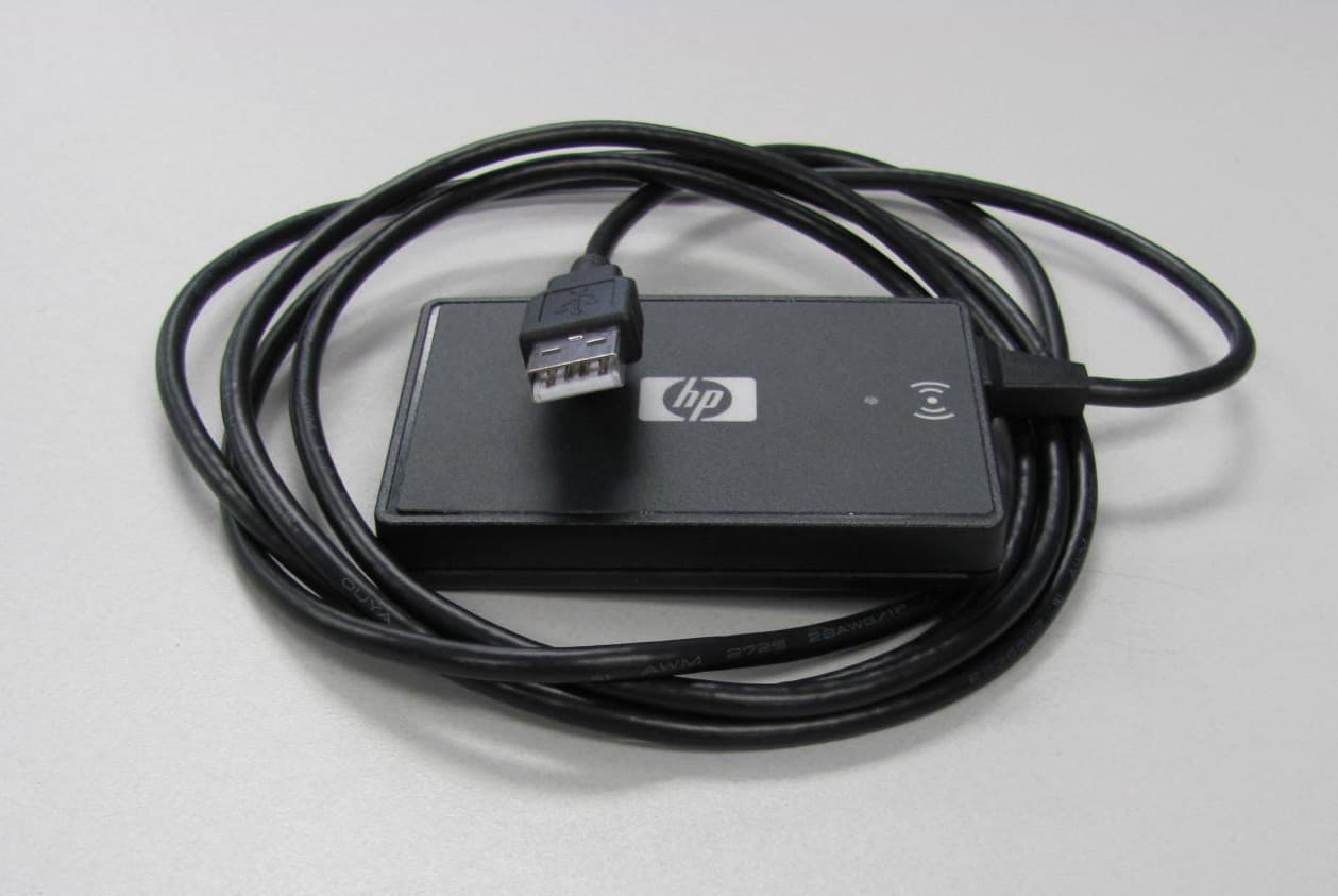
Jul 17, 2011Multi-Protocol RFID Reader
Equipment Class
DXX - Part 15 Low Power Communication Device Transmitter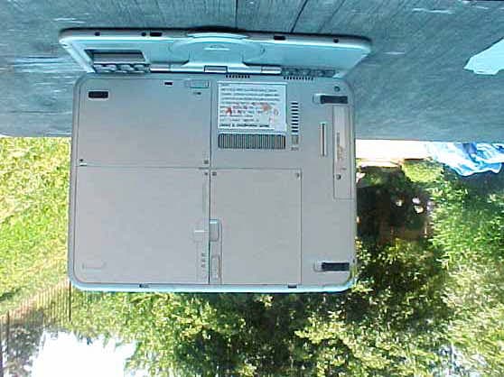
CNTWM3B2915ABG
Dec 19, 2004Intel Mini PCI Type 802.11ABG WLAN Adapter
Equipment Class
NII - Unlicensed National Information Infrastructure TX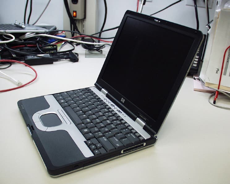
CNTPP2170SIL
Apr 08, 2004Laptop with WLAN and Bluetooth
Equipment Class
DTS - Digital Transmission System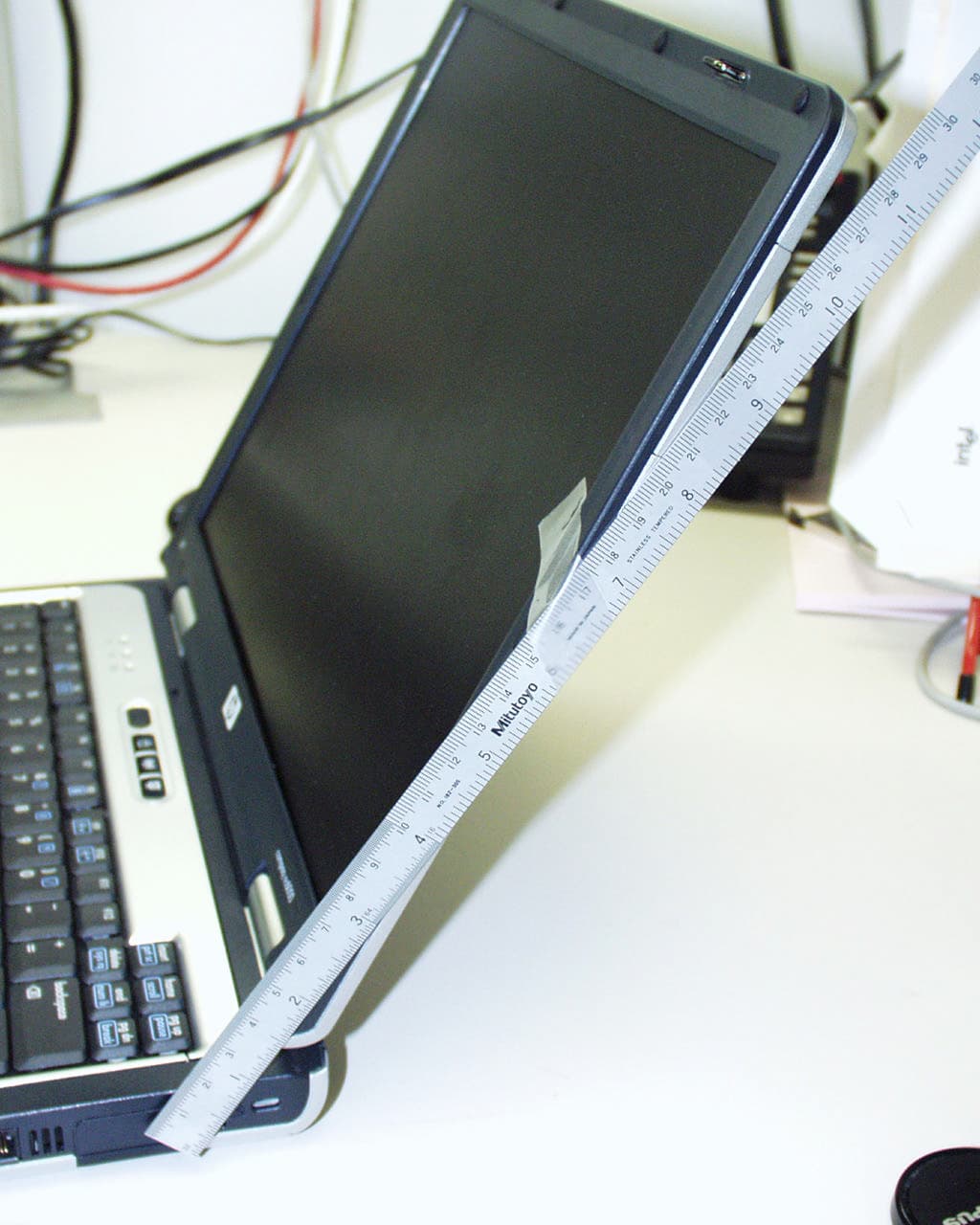
CNTWM3B2200BGA
Feb 29, 2004Laptop w/ Intel 802.11 BG Wireless LAN Adapter
Equipment Class
DTS - Digital Transmission System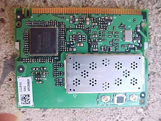
CNTHSTNN-I01C
Nov 13, 2003Notebook PC with Built-in Wireless
Equipment Class
DTS - Digital Transmission System