CNTPP2190Notebook PC with Built-in Wireless
HP Inc.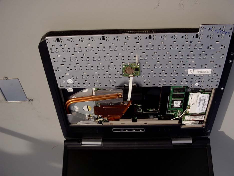
Click to zoom
Application Details
- Equipment Class
- DSS - Part 15 Spread Spectrum Transmitter
- Date of Grant
- Sep 11, 2003
- Application Purpose
- Original Equipment
- Date of Application
- Sep 11, 2003
- Equipment Note
- Notebook PC with Built-in Wireless
- Frequency Range
- 2412.00000000 - 2462.00000000
- Company
- HP Inc.
- Country
- United States
Documents & Files
Document Text
Text extracted from the exhibit documents filed with the FCC. Open a document above to read the original.
Users Manual
Intel(R) PRO/Wireless LAN Mini PCI Adapter User's Guide This document provides information for the following wireless devices: l Intel(R) PRO/Wireless LAN 7100 3B Mini PCI Adapter, operating at 5 GHz l Intel(R) PRO/Wireless LAN 2100 3B Mini PCI Adapter, operating at 2.4 GHz These wireless adapters operate with high-capacity networks using multiple access points within large or small environments. Using the Intel(R) PROSet Windows utility you can configure, manage wireless local area network (WLAN) management tasks, adapter switching functions, and connections. Wireless LAN General Information About Wireless LAN Technology Administrator's Guide Adapter Setup and Configuration Software Installation Using PROSet Connecting to a Network Security Overview Setting Up Security Troubleshooting Specifications Glossary Support and Warranty Customer Support Software License Safety and Regulatory Notices Limited Warranty Adapter Registration Legal Notices Copyright © 2002 Intel Corporation. All rights reserved. Intel Corporation, 5200 N.E. Elam Young Parkway, Hillsboro, OR 97124-6497 Intel Corporation assumes no responsibility for errors or omissions in this document. Nor does Intel make any commitment to update the information contained herein. Intel, Itanium, and Pentium are trademarks or registered trademarks of Intel Corporation or its subsidiaries in the United States and other countries. *Other names and brands may be claimed as the property of others. Back to Contents Page About Wireless LAN Technology l Choosing a WLAN l Configuring a WLAN l Identifying a WLAN l Surveying the Site of Your WLAN l Factors Affecting Range l Stronger Security A wireless network connects computers without using network cables. Computers use radio communications to send data between each other. You can communicate directly with other wireless computers, or connect to an existing network through a wireless access point. When you set up your wireless adapter, you select the operating mode for the kind of wireless network you want. You can use your Intel(R) PRO/Wireless adapter to connect to other similar wireless devices that comply with the 802.11 standard for wireless networking. Choosing a Wireless LAN Mode Wireless LANs can operate with or without access points, depending on the number of users in the network. Infrastructure mode uses access points to allow wireless computers to send and receive information. Wireless computers transmit to the access point, the access point receives the information and rebroadcasts it to other computers. The access point can also connect to a wired network or to the Internet. Multiple access points can work together to provide coverage over a wide area. Peer-to-Peer mode, also called Ad Hoc mode, works without access points and allows wireless computers to send information directly to other wireless computers. You can use Peer-to-Peer mode to network computers in a home or small office or to set up a temporary wireless network for a meeting. Configuring a Wireless LAN There are three basic components that must be configured for a wireless LAN to operate properly: l Network Name—Each wireless network uses a unique Network Name to identify the network. This name is called the Service Set Identifier (SSID). When you set up your wireless adapter, you specify the SSID. If you want to connect to an existing network, you must use the name for that network. If you are setting up your own network you can make up your own name and use it on each computer. The name can be up to 32 characters long and contain letters and numbers. l Profiles—When you set up your computer to access a wireless network, Intel(R) PROSet creates a profile for the wireless settings that you specify. If you want to connect to another network, you can scan for existing networks and make a temporary connection, or create a new profile for that network. After you create profiles, your computer will automatically connect when you change locations. l Security—The 802.11 wireless networks use encryption to help protect your data. Wired equivalent privacy (WEP) uses a 64-bit or 128-bit shared encryption key to scramble data. Before a computer transmits data, it scrambles the data using the secret encryption key. The receiving computer uses this same key to unscramble the data. If you are connecting to an existing network, use the encryption key provided by the administrator of the wireless network. If you are setting up your own network you can make up your own key and use it on each computer. Identifying a Wireless Network Depending on the size and components of a wireless LAN, there are many ways to identify a wireless LAN: l The Network Name or Service Set Identifier (SSID)—Identifies a wireless network. All wireless devices on the network must use the same SSID. l Extended Service Set Identifier (ESSID)—A special case of SSID used to identify a wireless network that includes access points. l Independent Basic Service Set Identifier (IBSSID)—A special case of SSID used to identify a network of wireless computers configured to communicate directly with one another without using an access point. l Basic Service Set Identifier (BSSID)—A unique identifier for each wireless device. The BSSID is the Ethernet MAC address of the device. l Broadcast SSID—An access point can respond to computers sending probe packets with the broadcast SSID. If this feature is enabled on the access point, any wireless user can associate with the access point by using a blank (null) SSID. Surveying the Site of Your Wireless LAN Conducting a site survey for your wireless LAN is the most crucial step in the process of setting up a wireless network. It greatly reduces the amount of troubleshooting you will have to do once you have the wireless LAN set up and ready for connection testing. To conduct a site survey, you will need the following tools: l An access point (or laptop computer) that is set up to be the transmitter. It should be mounted near a…
Text truncated - open the document above for the full version.
Users Manual
Hardware Guide HP Compaq Notebook Series Document Part Number: 333955-001 August 2003 This guide explains how to identify and use notebook hardware features, including connectors for external devices. It also includes power and environmental specifications, which may be helpful when traveling with the notebook. 333955-001.book Page i Monday, July 14, 2003 11:27 AM © 2003 Hewlett-Packard Development Company, L.P. Microsoft and Windows are trademarks of Microsoft Corporation in the U.S. and/or other countries. Intel and SpeedStep are trademarks of Intel Corporation in the US and/or other countries. SD Logo is a trademark. The information contained herein is subject to change without notice. The only warranties for HP products and services are set forth in the express warranty statements accompanying such products and services. Nothing herein should be construed as constituting an additional warranty. HP shall not be liable for technical or editorial errors or omissions contained herein. Hardware Guide HP Compaq Notebook Series First Edition August 2003 Reference Number: nc8000/nw8000 Document Part Number: 333955-001 333955-001.book Page iii Monday, July 14, 2003 11:27 AM Hardware Guideiii Contents 1 Notebook Features Pointing Device Components. . . . . . . . . . . . . . . . . . . . . . 1–1 Top Components . . . . . . . . . . . . . . . . . . . . . . . . . . . . . . . 1–2 Lights . . . . . . . . . . . . . . . . . . . . . . . . . . . . . . . . . . . . . . . . 1–5 Left Side Components . . . . . . . . . . . . . . . . . . . . . . . . . . . 1–7 Right Side Components . . . . . . . . . . . . . . . . . . . . . . . . . . 1–9 Front View Components . . . . . . . . . . . . . . . . . . . . . . . . 1–11 Rear Panel Components . . . . . . . . . . . . . . . . . . . . . . . . . 1–12 Bottom Components. . . . . . . . . . . . . . . . . . . . . . . . . . . . 1–14 Labels . . . . . . . . . . . . . . . . . . . . . . . . . . . . . . . . . . . . . . . 1–16 2 Pointing Devices and Keyboard Using a Pointing Device. . . . . . . . . . . . . . . . . . . . . . . . . . 2–1 Using the Pointing Stick . . . . . . . . . . . . . . . . . . . . . . 2–3 Using the TouchPad. . . . . . . . . . . . . . . . . . . . . . . . . . 2–3 Using an External Mouse . . . . . . . . . . . . . . . . . . . . . 2–4 Setting Pointing Device Preferences . . . . . . . . . . . . . 2–4 Using Hotkeys and Shortcut Keys . . . . . . . . . . . . . . . . . . 2–5 Identifying fn and Function Keys . . . . . . . . . . . . . . . 2–5 Hotkey and Shortcut Key Quick Reference . . . . . . . 2–6 Initiating Standby (fn+f3) . . . . . . . . . . . . . . . . . . . . . 2–7 Switching Displays (fn+f4) . . . . . . . . . . . . . . . . . . . . 2–7 Viewing Battery Charge Information (fn+f8) . . . . . . 2–8 Decreasing Screen Brightness (fn+f9). . . . . . . . . . . . 2–8 333955-001.book Page iii Monday, July 14, 2003 11:27 AM ivHardware Guide Contents Increasing Screen Brightness (fn+f10) . . . . . . . . . . . 2–8 Displaying System Information (fn+esc) . . . . . . . . . 2–9 Using Hotkeys and Shortcut Keys with External Keyboards . . . . . . . . . . . . . . . . . . . . . . . . . . . . . . . . . 2–9 Using Quick Launch Buttons . . . . . . . . . . . . . . . . . . . . . 2–10 Using Keypads . . . . . . . . . . . . . . . . . . . . . . . . . . . . . . . . 2–12 Using the Embedded Numeric Keypad . . . . . . . . . . 2–12 Using an External Keypad . . . . . . . . . . . . . . . . . . . . 2–14 3 Battery Packs Running the Notebook on Battery Power . . . . . . . . . . . . 3–1 Identifying Battery Packs . . . . . . . . . . . . . . . . . . . . . . . . . 3–2 Inserting or Removing a Primary Battery Pack . . . . . . . . 3–3 Inserting or Removing a MultiBay Battery Pack . . . . . . . 3–5 Charging a Battery Pack. . . . . . . . . . . . . . . . . . . . . . . . . . 3–7 Charging a New Battery Pack . . . . . . . . . . . . . . . . . . 3–8 Charging an In-Use Battery Pack . . . . . . . . . . . . . . . 3–8 Charging a Primary and MultiBay Battery Pack . . . . 3–8 Monitoring the Charge in a Battery Pack. . . . . . . . . . . . . 3–9 Obtaining Accurate Charge Information . . . . . . . . . . 3–9 Displaying Charge Information on the Screen . . . . . 3–9 Displaying Charge Information on a MultiBay Battery Pack. . . . . . . . . . . . . . . . . . . . . . . . . . . . . . . 3–11 Managing Low-Battery Conditions . . . . . . . . . . . . . . . . 3–12 Identifying Low-Battery Conditions . . . . . . . . . . . . 3–12 Resolving Low-Battery Conditions . . . . . . . . . . . . . 3–13 Calibrating a Battery Pack . . . . . . . . . . . . . . . . . . . . . . . 3–14 When to Calibrate . . . . . . . . . . . . . . . . . . . . . . . . . . 3–14 Battery Conservation Procedures and Settings . . . . . . . 3–18 Conserving Power as You Work . . . . . . . . . . . . . . . 3–18 Selecting Power Conservation Settings . . . . . . . . . . 3–19 Storing a Battery Pack . . . . . . . . . . . . . . . . . . . . . . . . . . 3–20 Disposing of a Used Battery Pack . . . . . . . . . . . . . . . . . 3–21 Finding More Power Information . . . . . . . . . . . . . . . . . 3–21 333955-001.book Page iv Monday, July 14, 2003 11:27 AM Contents Hardware Guidev 4 Drives Caring for Drives . . . . . . . . . . . . . . . . . . . . . . . . . . . . . . . 4–1 Adding a Drive to the System . . . . . . . . . . . . . . . . . . . . . 4–3 Hard Drive . . . . . . . . . . . . . . . . . . . . . . . . . . . . . . . . . . . . 4–4 Identifying the Hard Drive Activity Light. . . . . . . . . 4–4 Replacing the Primary Hard Drive . . . . . . . . . . . . . . 4–5 Optical Drive . . . . . . . . . . . . . . . . . . . . . . . . . . . . . . . . . . 4–9 Inserting an Optical Disc . . . . . . . . . . . . . . . . . . . . . . 4–9 Removing an Optical Disc (with Power). . . . . . . . . 4–10 Removing an Optical Disc (No Power) . . . . . . . . . . 4–11 Displaying Optical Disc Contents . . . . . . . . . . . . . . 4–12 Locating Optical Disc Software . . . . . . . . . . . . . . . 4–12 Initiating Standby or Hibernation . . . . . . . . . .…
Text truncated - open the document above for the full version.
Users Manual
Hardware Guide4–1 4 Drives Caring for Drives Drives are fragile notebook components that must be handled with care. The following cautions apply to all drives. Additional cautions are included with the procedures to which they apply. 333955-001.book Page 1 Monday, July 14, 2003 11:27 AM 4–2Hardware Guide Drives Ä CAUTION: To prevent loss or damage to the notebook or a drive: ■Handle a drive carefully. Do not drop it. ■Excessive force can damage drive connectors. When you insert a drive, use only enough force to seat the drive. ■Do not spray a drive with cleaning fluid or other liquid or expose it to temperature extremes. ■Do not remove the primary hard drive (the hard drive in the hard drive bay) except for repair or replacement. ■Electrostatic discharge can damage electronic components. To prevent electrostatic damage to the notebook or a drive: ❏Discharge yourself from static electricity before handling a drive by touching a grounded metal object; and ❏Avoid touching the connectors on a drive. ❏For more information about preventing electrostatic damage, refer to the Regulatory and Safety Notices guide on the Documentation Library CD. ■Avoid exposing a drive or a diskette to devices with magnetic fields. Security devices with magnetic fields include airport walk-through devices and security wands. The airport security devices that check carry-on luggage, usually while it is placed on a conveyor belt, use x-rays instead of magnetism and will not damage a drive or a diskette. ■If you mail a drive, ship it in packaging that protects it from shock, vibration, temperature, and high humidity. Label the package “FRAGILE.” ✎ Airport security devices that check carry-on luggage placed on a conveyor belt use X-rays instead of magnetics and do not damage drives. 333955-001.book Page 2 Monday, July 14, 2003 11:27 AM Drives Hardware Guide4–3 Adding a Drive to the System Removable drives enable you to store and access data. ■A standard drive can be added to the system by inserting the drive into the notebook MultiBay or optional Advanced Port Replicator. ■A diskette drive can also be added. ■USB drives can be added by connecting the drives to USB connectors on the notebook or optional Port Replicator. For information about connecting a USB drive, refer to the “External Devices” chapter in this book. The notebook has 2 drive bays: ■The hard drive bay supports only a hard drive. The hard drive in the hard drive bay is the primary hard drive. ■The MultiBay supports any MultiBay device, including the following: ❏Hard drive (inserted into a MultiBay hard drive adapter) ❏CD or CD-RW drive ❏DVD or DVD/CD-RW combination drive ❏DVD+RW drive ❏Diskette drive ❏MultiBay battery 333955-001.book Page 3 Monday, July 14, 2003 11:27 AM 4–4Hardware Guide Drives Hard Drive This section discusses the primary hard drive of the notebook. Identifying the Hard Drive Activity Light The hard drive activity light turns on when the primary hard drive or integrated optical drive is being accessed. 333955-001.book Page 4 Monday, July 14, 2003 11:27 AM Drives Hardware Guide4–5 Replacing the Primary Hard Drive The hard drive in the hard drive bay is the primary hard drive. Remove it only after the notebook is properly shut down. Ä CAUTION: To prevent system lockup and loss of information: ■Shut down the notebook before removing the hard drive from the hard drive bay. Do not remove the hard drive while the notebook is on, in Standby, or in Hibernation. ■If you are not sure whether the notebook is off or in Hibernation, turn the notebook on by pressing the power button. Then shut down the notebook through the operating system. To remove the primary hard drive: 1. Save your work. 2. Shut down the notebook and close the display. 3. Turn the notebook upside down. 4. Remove the hard drive cover retaining screw. 333955-001.book Page 5 Monday, July 14, 2003 11:27 AM 4–6Hardware Guide Drives 5. Slide the hard drive latch 1 forward to open the hard drive compartment, and remove the hard drive cover 2. 6. Lift the hard drive and remove it from the compartment. 333955-001.book Page 6 Monday, July 14, 2003 11:27 AM Drives Hardware Guide4–7 To replace the primary hard drive: 1. Slide the hard drive into the hard drive compartment. 2. Replace the hard drive cover and push down until the cover is latched into place. 333955-001.book Page 7 Monday, July 14, 2003 11:27 AM 4–8Hardware Guide Drives 3. Replace the hard drive cover retaining screw. 333955-001.book Page 8 Monday, July 14, 2003 11:27 AM Drives Hardware Guide4–9 Optical Drive This section describes how to use optical discs in the integrated optical drive. Inserting an Optical Disc 1. Turn on the notebook. 2. Press the release button 1 on the drive bezel to release the media tray. 3. Pull the tray 2 out until it is fully extended. Position a CD or DVD over the tray with the label side up. 4. Gently press the disc 3 onto the tray spindle until the disc snaps into place. Handle the disc by the edges, not the flat surfaces. If the media tray is not fully extended, tilt the disc to position it over the tray spindle, then press it into position. 5. Close the media tray. ✎ After you insert a DVD, a short pause is normal as Autorun opens the DVD and WinDVD player. 333955-001.book Page 9 Monday, July 14, 2003 11:27 AM 4–10Hardware Guide Drives Removing an Optical Disc (with Power) To remove a disc when power is available: 1. Turn on the notebook. 2. Press the release button 1 on the drive bezel to release the media tray, then pull the tray 2 out until it is fully extended. 3. Remove the disc 3 from the tray by gently pushing down on the spindle while lifting the outer edges of the disc. Handle the disc by the edges, not the flat surfaces. If the media tray is not fully extended, tilt the disc as you remove it. 4. Close the media tray and place the disc in a protective case. 333955-001.book Page 10 Monday, July 14, 2003 11:27 AM Drives Hardware Guide4–11 Removing an Optical Disc (No Power) To remove a…
Text truncated - open the document above for the full version.
Cover Letter(s)
Hewlett-Packard Company 20555 SH 249 Houston, TX 77070 www.hp.com David Wissel 281.518.3102 Tel 281.927.4536 Fax [email protected] August 25, 2003 Federal Communications Commission 7435 Oakland Mills Road Columbia, Maryland 21046 Subject: Request for withholding from public disclosure the schematics, block diagrams, and theory of operations. Gentlemen: We, Hewlett-Packard Company would like to request that the schematics, block diagrams, and theory of operations submitted with the application for certification be withheld from public disclosure as per Section 0.459 (d) of the FCC Rules. This request is made under the provisions of Section 0.457 (d) of the FCC Rules and Section 552 (b) (4) of the Freedom of Information Act. These sections authorize as a withholding from public inspection materials, which would be privileged as a matter of law if retained by the person submitting them, and materials which would not customarily be released to the public by that person. If you have any questions, please do not hesitate to contact us at 281-518-3102. Sincerely, ____________________________ ________________ David Wissel Date PSG Global Business Units Mobile Computing
Cover Letter(s)
August 11, 2003 American TCB 6731 Whittier Ave., Suite C110 McLean, VA 22101 Gentlemen: The attached documentation is provided in support of a formal submission to your organization for FCC certification of an intentional unlicensed transmitter. On behalf of our client, Aegis Labs has included an application for a Grant of Equipment Authorization pursuant to Subpart C of part 15 of FCC Rules (47 CFR) regarding intentional radiators. The data within the test report demonstrates the equipment was tested in a manner described under Part 2 and 15 of the Code of Federal Regulations. This submittal is for approval of the 802.11b MiniPCI Type IIIB Wireless Module (MN: WM3B2100, FCC ID: CNTPP2190) installed in a Hewlett Packard Company laptop computer (Series PP2190 with a set of Winstron NeWeb Corporation triple band antennas. For this submittal the 802.11b MiniPCI Type IIIB Wireless Module (MN: WM3B2100, FCC ID: CNTPP2190) is not considered the EUT (Equipment Under Test). The EUT is the Hewlett Packard Company laptop series PP2190. If there are any additional questions or if further information is needed, please contact us at your earliest convenience. Sincerely, Rick Candelas Aegis Labs, Inc. Lab Manager Enclosure (1 Emissions Test Report + Exhibits) AEGIS LABS, INC 22431 Antonio Parkway B160-417, Rancho Santa Margarita, CA 92688 949-459-7886 TEL 949-459-7869 FAX www.aegislabsinc.com
Cover Letter(s)
August 25, 2003 RE: Hewlett Packard Company FCC ID: CNTPP2190 Answers to the ATCB comments on the above referenced Application. 1.) The label supplied for this product has no FCC ID. Please supply revised label artwork. Refer to “Label – HPQ System (09-22-03)”. 2.) The Confidentiality Request contains items for which there are no exhibits. Please eliminate unused items from the letter. Refer to “Letter - Confidentiality (ATCB) (Rev. A, 08-22-03)” and “Letter - Confidentiality (FCC) (Rev. A, 08- 22-03)”. 3.) No required Operational Description exhibit was supplied. Refer to “Theory of Operation”. 4.) No required Block Diagram exhibit was supplied Refer to page 2 of “Schematic-Block Diagram”. 5.) Please see the Test Report. Page 6 of 46 refers to this device as a module [even though Cover Letter describes otherwise]. It does not appear that either a Modular Request or LMA is being sought. Please explain or revise. FYI: If you are simply adding a wireless LAN to a separately approved notebook computer, the FCC ID applies to the entire product. Refer to “Test Report – FCC (Rev. B, 09-22-03)”. 6.) Spectral Power Density test is typically taken over at minimum 1.5MHz span. This is to insure the highest peak is being recorded. Please provide a single worst case spectral power density plot over worst case channel and worst case data rate as a supplement to the existing report. Refer to “Test Report – FCC (Supplement) (09-22-03)”. 7.) Test Report identifies 11 channels as being implemented for 802.11b in the United States. However, the Manual seems to identify other channels to which this equipment – accidentally or otherwise – may be set. Please explain how only the US channel set for 802.11b will be implemented. If “passive scanning” techniques are used, please identify precautions which prevent this device from transmitting outside of the band even if this device finds an improperly tuned access point set to either channel 12 or 13. Refer to “Letter - Freq. Band Explanation”. 9.) FCC is now requiring a change in the MPE Estimation exhibits. Please calculate “S” (power density) at a distance of 20cm, and not the “safe MPE” distance. Refer to “MPE Calculations” Power density at the specific separation.
External Photos
View of the WLAN Transmitter Location Inside the Laptop (Shield Installed) WLAN Transmitter Shield View of the WLAN Transmitter Location Inside the Laptop WLAN Transmitter View of the WLAN Transmitter Location Inside the Laptop (Close-Up)
ID Label/Location Info
MoW RoW Approved by IDA for use in Singapore. DB02941 RLARN-03-0033 Instytut Lacznosci Potw. zgodn. Nr. 027/2003 CMII ID: 2003DJ0115 CE mark applicable only with Intel authorized antenna solutions 0682 NTC Type Accepted No.: ES D-0301543C N A T I O N A L T E L E C O M M U N I C A T I O N S C O M M I S S I O N CNC: 16-2737 SCT: RCPINWM03-004 URSEC: 143/FR/2002 TRC/SS/2003/3 SUBTEL: 30540/F-1 N04.377 CONATEL: N de Reg: 000041 0 0369-03-1096 Veja a documentação dos usuários para o barcode MTC: TRSS6968 SIRIM Contains Intel WLAN radio model WM3B2100 FCC ID: CNTPP2190 IC: 466Q-PP2190 349221-001 E E 92LP0425 Approved by IDA for use in Singapore. DB02941 RLARN-03-0033 Instytut Lacznosci Potw. zgodn. Nr. 027/2003 CMII ID: 2003DJ0115 CE mark applicable only with Intel authorized antenna solutions 0682 NTC Type Accepted No.: ES D-0301543C N A T I O N A L T E L E C O M M U N I C A T I O N S C O M M I S S I O N CNC: 16-2737 SCT: RCPINWM03-004 URSEC: 143/FR/2002 TRC/SS/2003/3 SUBTEL: 30540/F-1 N04.377 CONATEL: N de Reg: 000041 0 0369-03-1096 Veja a documentação dos usuários para o barcode MTC: TRSS6968 SIRIM Contains Intel WLAN radio model WM3B2100 349222-001
Internal Photos
Top View of the WLAN Transmitter “Insulation Removed” Bottom View of the WLAN Transmitter “Insulation Removed” Top View of the WLAN Transmitter “Shielding Removed” Top View of the WLAN Transmitter “With Insulation” Bottom View of the WLAN Transmitter “With Insulation”
RF Exposure Info
Document Number:03052801 Rev: 0A Regulatory Antenna Information 1/9 Ruby Regulatory Antenna Information Description : Triple-band Antenna(Main+Aux) Inventec Crop. P/N: 6036A0005501 6036A0005601 Wistron NeWeb P/N: 81.EB517.001 81.EB517.002 Wistron NeWeb Corporation No. 10-1,Li-hsin Road I, Science-base Industrial Park, Hsinchu 300,Taiwan, R.O.C. Tel: 886-3-6667799 Fax: 886-3-6667711 Provided by Wistron NeWeb Corp. Reviewed by Wistron NeWeb Corp. David Tau Eric Fang Document Number:03052801 Rev: 0A Regulatory Antenna Information 2/9 Antenna Information I. Antenna Assembly Specifications Antenna assembly overview: Peak Gain including cable loss. Designator Manufacture Antenna type Cable Assembly Info. Peak Gain W/ Cable loss (dBi) 2400-2500MHz 2.80 dBi (peak) 5150-5350MHz 2.09 dBi (peak) (P/N: 6036A0005501) Main antenna WNC PIFA (P/N:WN-S-1.13B-50 0MM(2-4-1)) 50 ohm Coaxial. length: 500mm diameter: 1.13mm Connector: IPEX 20278-111R-08 5470-5825MHz 2.72 dBi (peak) 2400-2500MHz 2.70 dBi (peak) 5150-5350MHz 1.20 dBi (peak) (P/N: 6036A0005601) Auxiliary antenna WNC PIFA (P/N: WN-S-1.13W-470MM( 2-4-1)) 50 ohm Coaxial. length: 470mm diameter: 1.13mm Connector: IPEX 20278-111R-08 5470-5825MHz 2.89 dBi (peak) Antenna overview: Peak Gain not including cable loss. Antenna Designator Manufacture Antenna type Peak Gain w/o Cable Loss (dBi) 2400-2500MHz 4.65dBi (peak) 5150-5350MHz 4.87dBi (peak) (P/N: 6036A0005501) Main antenna WNC PIFA 5470-5825MHz 5.59dBi (peak) 2400-2500MHz 4.54dBi (peak) 5150-5350MHz 3.85dBi (peak) (P/N: 6036A0005601) Auxiliary antenna WNC PIFA 5470-5825MHz 5.62dBi (peak) Document Number:03052801 Rev: 0A Regulatory Antenna Information 3/9 Cable assembly overview: Cable loss (including connector). Designator Manufacture Cable type and length VSWR Cable Loss (dB) 2400-2500MHz 1.64max 2400-2500MHz 1.85 dB (peak) 5150-5350MHz 1.73max 5150-5350MHz 2.78 dB (peak) (P/N:WN-S-1.13B-5 00MM(2-4-1)) For use with the Main antenna IPEX (P/N:WN-S-1.13B-5 00MM(2-4-1)) 50 ohm Coaxial. length: 500mm diameter: 1.13mm Connector: IPEX 20278-111R-08 5470-5825MHz 1.83max 5470-5825MHz 2.87 dB (peak) 2400-2500MHz 1.87max 2400-2500MHz 1.76dB (peak) 5150-5350MHz 2.07max 5150-5350MHz 2.65 dB (peak) (P/N: WN-S-1.13W-470M M(2-4-1)) For use with the Auxiliary antenna IPEX (P/N: WN-S-1.13W-470M M(2-4-1)) 50 ohm Coaxial. length: 470mm diameter: 1.13mm Connector: IPEX 20278-111R-08 5470-5825MHz 1.85max 5470-5825MHz 2.73 dB (peak) Drawing of antennae as follow. Document Number:03052801 Rev: 0A Regulatory Antenna Information 4/9 Radiation characteristic of antennae Loaded (In Host System) I. Peak Gain and Average Gain 2G4 ISM (2.400 GHz - 2.4835 GHz)U-NII (5.150 GHz - 5.350 GHz) HyperLAN (5.470 GHz - 5.825 GHz) Antenna Gain 2.40 GHz 2.45 GHz 2.50GHz5.15 GHz5.25 GHz5.35 GHz5.47 GHz 5.6475 GHz5.825 GHz Peak dBi 2.56 2.80 2.71 2.09 0.93 1.89 1.27 2.72 1.69 MAIN Avg dBi -1.60 -1.03 -1.21 -4.30 -4.06 -3.42 -3.43 -2.77 -3.16 Peak dBi 2.26 2.77 2.78 1.20 0.05 0.22 1.81 2.89 1.69 AUX Avg dBi -1.79 -1.53 -1.15 -4.54 -4.21 -3.92 -3.77 -2.31 -2.74 * Average Gain = 10log(Average (SQRT(V power 2 +H power 2 )))-Isotropic Gain **Peak Gain = 10log{Max [SQRT(V power 2 +H power 2 )]}-Isotropic Gain Average[ ] mean is sum all direction(250 point) and divide by 250 Max[ ] mean is chose maximum one on all direction(250 point ) II Radiation Pattern Main antenna [email protected] GHz Document Number:03052801 Rev: 0A Regulatory Antenna Information 5/9 Main antenna -@5 .2 5GHz Main antenna [email protected] Document Number:03052801 Rev: 0A Regulatory Antenna Information 6/9 AUX. Antenna [email protected] AUX. Antenna [email protected] Document Number:03052801 Rev: 0A Regulatory Antenna Information 7/9 AUX. Antenna [email protected] Document Number:03052801 Rev: 0A Regulatory Antenna Information 8/9 Host PC Information Host model:Ruby Drawing of antenna placement. Drawing showing the distance between the transmit (main) antenna and the user (excluding hands, wrist, feet, and ankle) AUX antenna Main antenna Main Ant. Around 27 cm Around 29cm Document Number:03052801 Rev: 0A Regulatory Antenna Information 9/9 Photographs of the antenna location Main Antenna Aux Antenna AUX ANT. Main ANT. Ruby LCD
RF Exposure Info
MPE Calculations Systems operating under the provision of 47 CFR 1.1307(b)(1) shall be operated in a manor that ensures that the public is not exposed to radio frequency energy levels in excess of the FCC guidelines. The EUT will only be used with a separation of 20 centimeters or greater between the antenna and the body of the user or nearby persons and can therefore be considered a mobile transmitter per 47 CFR 2.1091(b). The MPE calculation for this exposure is shown below. Using the Wintron NeWeb Triple Band Antennas: The peak radiated output power (EIRP) is calculated as follows: EIRP = P + G EIRP = 16.90dBm + 2.80 dBi EIRP = 19.70dBm (93.33 mW) Where P = Power input to the antenna (mW). G = Power gain of the antenna (dBi) Power density at the specific separation: S = PG/(4R 2 π) S = (48.98 x 1.905) / (4 x 20 2 x π) S = 0.019 mW/cm 2 Where S = Maximum power density (mW/cm 2 ) P = Power input to the antenna (mW). G = Numeric power gain of the antenna R = Distance to the center of the radiation of the antenna (20cm = limit for MPE) The maximum permissible exposure (MPE) for the general population is 1mW/cm 2 . The power density at 20cm does not exceed the 1mW/cm 2 limit. Therefore, the exposure condition is compliant with FCC rules. Estimated safe separation: R = PG/4π R = (48.98 x 1.905) / 4π R = 2.72 cm Where P …
Text truncated - open the document above for the full version.
Contact Information
Applicant
Richard P Tarsio(US Canada Technical Regulations)
Technical Contact
Aegis Labs, Inc.Rick Candelas
[email protected]954-459-7886
22431-B160 Antonio Parkway #417 · Rancho Santa Margarita, California · United States
Test Firm
Aegis Labs, Inc.Rick Candelas
Technical Specifications
| # | Rule Parts | Frequency Range | Power Output |
|---|---|---|---|
| 1 | 15C | 2.41 GHz - 2.46 GHz | 48.00 mW |
Other Applications from HP Inc.
CNTBOISB110600
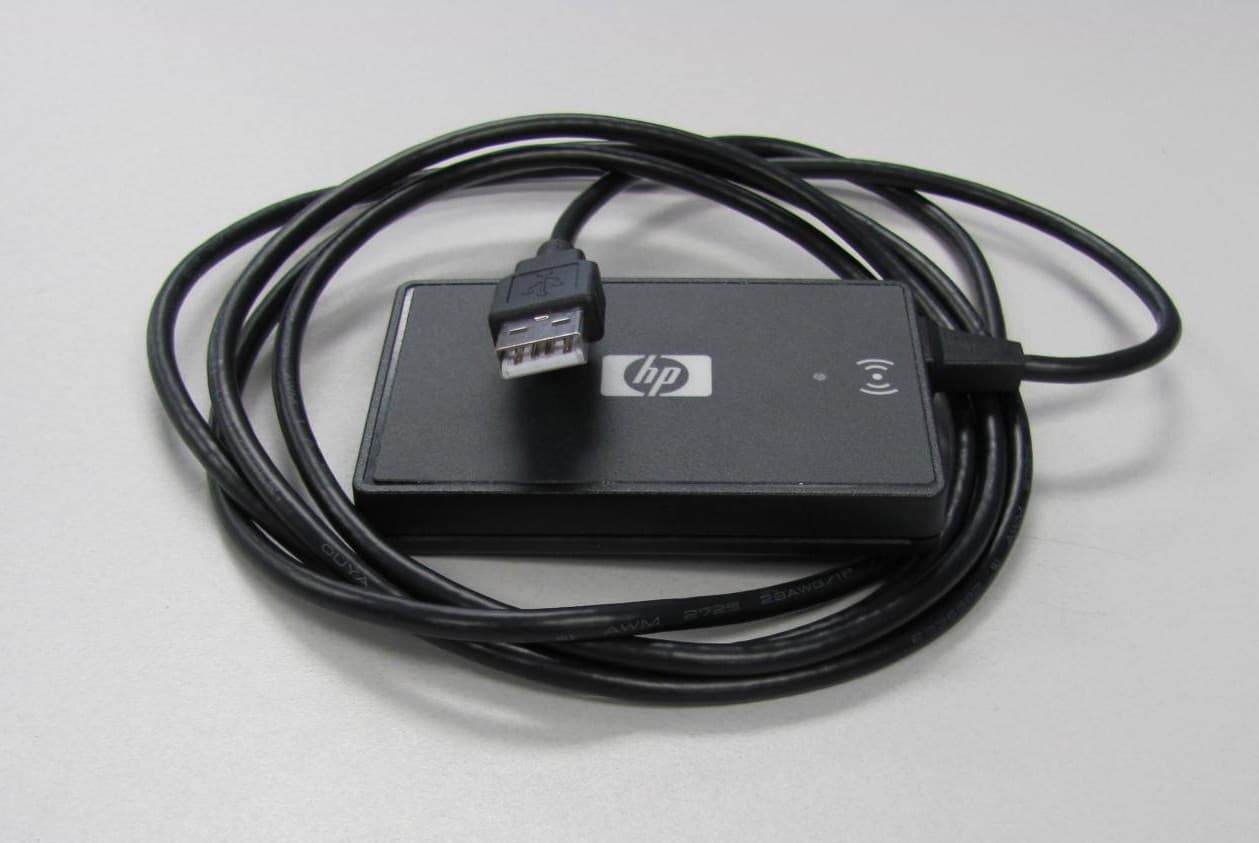
Jul 17, 2011Multi-Protocol RFID Reader
Equipment Class
DXX - Part 15 Low Power Communication Device Transmitter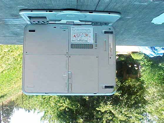
CNTWM3B2915ABG
Dec 19, 2004Intel Mini PCI Type 802.11ABG WLAN Adapter
Equipment Class
NII - Unlicensed National Information Infrastructure TX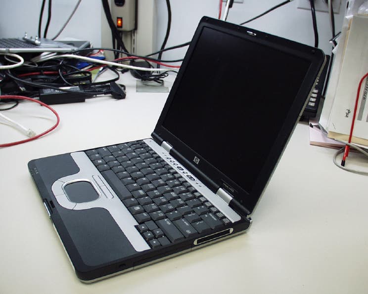
CNTPP2170SIL
Apr 08, 2004Laptop with WLAN and Bluetooth
Equipment Class
DTS - Digital Transmission System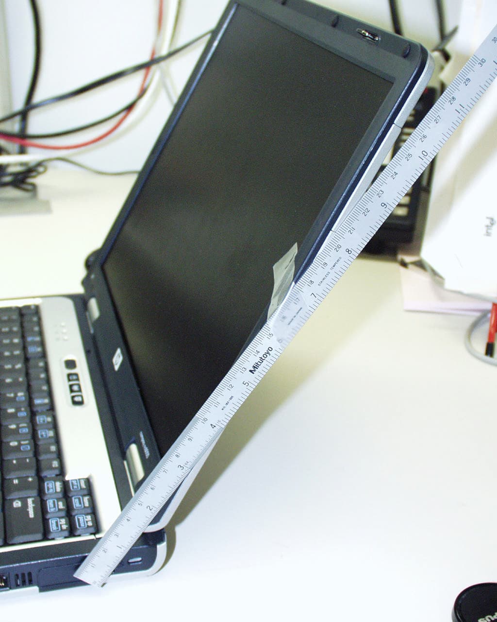
CNTWM3B2200BGA
Feb 29, 2004Laptop w/ Intel 802.11 BG Wireless LAN Adapter
Equipment Class
DTS - Digital Transmission System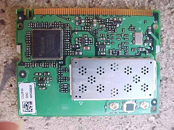
CNTHSTNN-I01C
Nov 13, 2003Notebook PC with Built-in Wireless
Equipment Class
DTS - Digital Transmission System