CNTPP3006Tablet PC with WLAN
HP Inc.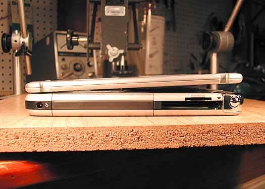
Click to zoom
Application Details
- Equipment Class
- DTS - Digital Transmission System
- Date of Grant
- Oct 14, 2003
- Application Purpose
- Original Equipment
- Date of Application
- Oct 14, 2003
- Equipment Note
- Tablet PC with WLAN
- Frequency Range
- 2412.00000000 - 2462.00000000
- Company
- HP Inc.
- Country
- United States
Documents & Files
Document Text
Text extracted from the exhibit documents filed with the FCC. Open a document above to read the original.
Users Manual
Hardware Guide HP Tablet PC Series Document Part Number: 331734-001 October 2003 This guide explains how to identify, use, modify, and maintain the hardware features on the tablet PC and keyboard. It also includes power, networking, and environmental specifications, which may be helpful when traveling with the tablet PC. 331734-001.book Page i Monday, July 14, 2003 3:47 PM © 2003 Hewlett-Packard Development Company, L.P. Microsoft and Windows are trademarks of Microsoft Corporation in the U.S. and/or other countries. SD Logo is a trademark. The information contained herein is subject to change without notice. The only warranties for HP products and services are set forth in the express warranty statements accompanying such products and services. Nothing herein should be construed as constituting an additional warranty. HP shall not be liable for technical or editorial errors or omissions contained herein. Hardware Guide HP Tablet PC Series First Edition October 2003 Reference Number: TC1100/TR1105 Document Part Number: 331734-001 331734-001.book Page ii Monday, July 14, 2003 3:47 PM Hardware Guideiii Contents 1 External Components Pen Components. . . . . . . . . . . . . . . . . . . . . . . . . . . . . . . . 1–1 Tablet PC Components . . . . . . . . . . . . . . . . . . . . . . . . . . 1–2 Front: Lights and Bluetooth. . . . . . . . . . . . . . . . . . . . 1–2 Front: Pen-Activated Buttons . . . . . . . . . . . . . . . . . . 1–3 Right Side: Power Switch and Power/Standby Light . . . . . . . . . . . . . . . . . . . . . . . . . 1–4 Right Side: Windows Security and Display Toggle Buttons . . . . . . . . . . . . . . . . . . . . . . . 1–5 Right Side: Esc, Tab and Q Menu Buttons . . . . . . . . 1–6 Right Side: Jog Dial and Antenna . . . . . . . . . . . . . . . 1–7 Lower Side. . . . . . . . . . . . . . . . . . . . . . . . . . . . . . . . . 1–8 Left Side: Attachment Slots and Keyboard Connector . . . . . . . . . . . . . . . . . . . . . . . . . 1–9 Left Side: Security Cable Slot, Vent and Antenna . . . . . . . . . . . . . . . . . . . . . . . . . . . . . . . . . . 1–10 Top: Connectors and Jacks . . . . . . . . . . . . . . . . . . . 1–11 Top: Pen Holder and LAN Connection Lights . . . . 1–12 Top: Card Slots, Buttons and Tether Eyelet . . . . . . 1–13 Back: Attachment Features and Hard Drive Bay . . . . . . . . . . . . . . . . . . . . . . . . . . . . 1–14 Back: Battery Bay . . . . . . . . . . . . . . . . . . . . . . . . . . 1–15 Back: Memory and Mini PCI Compartment . . . . . . 1–16 Back: Labels . . . . . . . . . . . . . . . . . . . . . . . . . . . . . . 1–17 Back: Tilt Feet and Pad Feet . . . . . . . . . . . . . . . . . . 1–18 331734-001.book Page iii Monday, July 14, 2003 3:47 PM ivHardware Guide Contents Additional Tablet PC Standard Components . . . . . . . . . 1–19 Documentation CDs . . . . . . . . . . . . . . . . . . . . . . . . 1–20 Cords and Cables . . . . . . . . . . . . . . . . . . . . . . . . . . . 1–21 Adapters and Accessories . . . . . . . . . . . . . . . . . . . . 1–22 Tablet PC Keyboard Components . . . . . . . . . . . . . . . . . 1–23 Front: Lights and Pointing Device. . . . . . . . . . . . . . 1–23 Front: Keys . . . . . . . . . . . . . . . . . . . . . . . . . . . . . . . 1–24 Front: Positioning and Security Features. . . . . . . . . 1–25 Top. . . . . . . . . . . . . . . . . . . . . . . . . . . . . . . . . . . . . . 1–26 Back . . . . . . . . . . . . . . . . . . . . . . . . . . . . . . . . . . . . . 1–27 Additional Keyboard Standard Component . . . . . . 1–28 2 Pen, Command Controls and Keyboards Pen . . . . . . . . . . . . . . . . . . . . . . . . . . . . . . . . . . . . . . . . . . 2–1 Entering Information with the Pen . . . . . . . . . . . . . . 2–2 Calibrating the Pen . . . . . . . . . . . . . . . . . . . . . . . . . . 2–4 Setting Pen Preferences . . . . . . . . . . . . . . . . . . . . . . . 2–5 Command Controls . . . . . . . . . . . . . . . . . . . . . . . . . . . . . 2–6 Identifying Command Controls . . . . . . . . . . . . . . . . . 2–6 Command Controls Quick Reference . . . . . . . . . . . . 2–7 Using Command Controls . . . . . . . . . . . . . . . . . . . . . 2–8 Setting Command Control Preferences . . . . . . . . . . 2–14 On-Screen Keyboard . . . . . . . . . . . . . . . . . . . . . . . . . . . 2–17 Tablet PC Keyboard . . . . . . . . . . . . . . . . . . . . . . . . . . . . 2–18 Using the Pointing Device . . . . . . . . . . . . . . . . . . . . 2–19 Using the Keypad . . . . . . . . . . . . . . . . . . . . . . . . . . 2–20 Using F11/F12 . . . . . . . . . . . . . . . . . . . . . . . . . . . . 2–23 331734-001.book Page iv Monday, July 14, 2003 3:47 PM Contents Hardware Guidev 3 Battery Packs Running the Tablet PC on Battery Power . . . . . . . . . . . . 3–1 Replacing a Battery Pack . . . . . . . . . . . . . . . . . . . . . . . . . 3–2 Removing a Battery Pack . . . . . . . . . . . . . . . . . . . . . 3–2 Inserting a Battery Pack. . . . . . . . . . . . . . . . . . . . . . . 3–4 Securing a Battery Pack . . . . . . . . . . . . . . . . . . . . . . . . . . 3–6 Accessing the Battery Pack Security Screw . . . . . . . 3–6 Inserting a Battery Pack Security Screw . . . . . . . . . . 3–7 Charging a Battery Pack. . . . . . . . . . . . . . . . . . . . . . . . . . 3–8 Charging a New Battery Pack . . . . . . . . . . . . . . . . . . 3–9 Charging an In-Use Battery Pack . . . . . . . . . . . . . . . 3–9 Monitoring the Charge in a Battery Pack. . . . . . . . . . . . 3–10 Obtaining Accurate Charge Information . . . . . . . . . 3–10 Displaying Charge Information on the Screen . . . . 3–10 Displaying Charge Information on a Battery Pack. . . . . . . . . . . . . . . . . . . . . . . . . . . . . . . 3–12 Managing Low-Battery Conditions . . . . . . . . . . . . . . . . 3–13 Identifying Low-Battery Conditions . . . . . . . . . . . . 3–13 Resolving Low-Battery Conditions . . . . . . . . . . . . . 3–14 Initiating and Resuming from Standby or Hibernation . . . . . . . . . . . . . . . . . . . . . . . . . . . . . . . 3–15…
Text truncated - open the document above for the full version.
Users Manual
Hardware Guide3–1 3 Battery Packs Running the Tablet PC on Battery Power When the tablet PC is connected to external power, the tablet PC runs on external power. When a charged battery pack is in the tablet PC and the tablet PC is not connected to external power, the tablet PC runs on battery power. The tablet PC switches between external power and battery power according to the availability of an external power source. For example, if the tablet PC contains a charged battery pack and is running on external power supplied through the AC adapter, the tablet PC will switch to battery power if the AC adapter is disconnected from the tablet PC. Whether to leave a battery pack in the tablet PC or in storage depends on how you work. Keeping a battery pack in the tablet PC enables the battery pack to charge whenever the tablet PC is connected to external power and also protects your work in case of a power outage. On the other hand, a battery pack in the tablet PC slowly discharges even while the tablet PC is turned off. If you will not be using the tablet PC for one month or more, removing the battery pack and storing it as described in “Storing a Battery Pack,” later in this chapter, will prolong its life. For more information about leaving your work, refer on this CD to the Software Guide, “Power” chapter. 331734-001.book Page 1 Monday, July 14, 2003 3:47 PM 3–2Hardware Guide Battery Packs Replacing a Battery Pack Removing a Battery Pack Ä CAUTION: To prevent loss of work when removing a battery pack that is running the tablet PC, initiate Hibernation or turn off the tablet PC before removing the battery pack. ■If you remove a battery pack that is running the tablet PC while the tablet PC is in Standby, your work is saved in Standby for up to one minute, then the tablet PC shuts down and your unsaved work is lost. ■If you remove a battery pack that is running the tablet PC while the tablet PC is on, the tablet PC shuts down immediately and your unsaved work is lost. To remove a battery pack from the tablet PC: 1. Turn the tablet PC front side down. (If a battery pack security screw is in place, remove the screw.) 331734-001.book Page 2 Monday, July 14, 2003 3:47 PM Battery Packs Hardware Guide3–3 2. To unlock the battery pack release latch, slide the latch firmly toward the unlock icon 1. Then hold the latch as you disengage the 2 tabs on the battery pack from the 2 slots on the battery bay 2 and lift the battery pack out of the battery bay 3. Removing a battery pack 331734-001.book Page 3 Monday, July 14, 2003 3:47 PM 3–4Hardware Guide Battery Packs Inserting a Battery Pack To insert a battery pack into the tablet PC: 1. Turn the tablet PC front side down. 2. Align the 2 rectangular tabs 1 on the battery pack with the 2 rectangular alignment slots 2 in the battery bay. Aligning the battery pack tabs with the battery bay alignment slots 331734-001.book Page 4 Monday, July 14, 2003 3:47 PM Battery Packs Hardware Guide3–5 3. Angle the battery pack toward the alignment slots 1 until the 2 tabs are inserted into the 2 alignment slots 2. 4. Tilt the battery pack downward until it snaps into place 3. Inserting a battery pack 5. If you initiated Standby or Hibernation before replacing the battery pack, slide and release the power switch to resume from Standby or Hibernation. 331734-001.book Page 5 Monday, July 14, 2003 3:47 PM 3–6Hardware Guide Battery Packs Securing a Battery Pack Use the battery pack security screw to hold the battery pack in place, and to provide antitheft protection for the battery pack. Accessing the Battery Pack Security Screw A battery pack security screw ships inside the battery bay. To access the battery pack security screw: 1. Remove the battery pack as instructed in “Removing a Battery Pack” earlier in this section. 2. Remove the battery pack security screw. Removing the battery pack security screw 331734-001.book Page 6 Monday, July 14, 2003 3:47 PM Battery Packs Hardware Guide3–7 Inserting a Battery Pack Security Screw To secure the battery pack in the battery bay with a battery pack security screw: 1. Insert the battery pack into the battery bay as instructed in “Inserting a Battery Pack” earlier in this section. 2. Insert a battery pack security screw through the battery pack case and into the tablet PC. Inserting a battery pack security screw 331734-001.book Page 7 Monday, July 14, 2003 3:47 PM 3–8Hardware Guide Battery Packs Charging a Battery Pack The battery pack in the tablet PC charges whenever the tablet PC is connected to external power. The battery pack charges whether or not the tablet PC is in use, but charges faster when the tablet PC is off. Charging may be delayed if a battery pack is new, has not been used for 2 weeks or more, or is much warmer or cooler than room temperature. Charging times vary. The battery light displays charge status: ■On: the battery pack is charging. ■Off: the battery pack is fully charged. ■Flashing: the battery pack has 5 percent or less of a full charge. Identifying the battery light 331734-001.book Page 8 Monday, July 14, 2003 3:47 PM Battery Packs Hardware Guide3–9 Charging a New Battery Pack Fully charge the battery pack while the tablet PC is connected to external power through the AC adapter. A new battery pack that has been partially charged, but not fully charged, can run the tablet PC, but battery charge displays may be inaccurate. Charging an In-Use Battery Pack To prolong battery life and increase the accuracy of battery charge displays: ■Allow the battery pack to discharge to less than 10 percent of a full charge through normal use before charging it. ■When you charge the battery pack, charge it fully. An in-use battery pack can be charged while the tablet PC is connected to external power through the AC adapter or an optional Automobile Power Adapter Charger, Docking Station, or DC cable. An optional Auto/Air Cable can be used to run the tablet PC, but cannot be used to charge a battery pack. 331734-001.book Page 9…
Text truncated - open the document above for the full version.
Users Manual
Hardware Guide8–1 8 External Device Connections Standard Device The jacks and connectors described in this guide support standard external devices. ■For information about which jack or connector to use, refer to the documentation included with the device. ■For information about installing or loading any software required by the device, refer to the device documentation, the operating system Help files, or the device manufacturer’s Web site. To connect a standard external device to the tablet PC: 1. If you are connecting a powered device, be sure the device is turned off. 2. Connect the device to a jack or connector on the tablet PC. 3. If you are connecting a powered device, plug the device power cord into a grounded electrical outlet. 4. Turn on the device. ✎ If a properly connected display device does not display an image, try pressing the Q menu button > Internal and External item or External Only item to switch the image to the new device. To disconnect a standard external device from the tablet PC, turn off the device (if it is powered), then disconnect the device from the tablet PC. 331734-001.book Page 1 Monday, July 14, 2003 3:47 PM 8–2Hardware Guide External Device Connections USB Device USB is a hardware interface that can be used to connect external devices such as a USB keyboard, mouse, drive, printer, scanner, or hub to the tablet PC or an optional Docking Station. A USB device functions in the system in the same way as a comparable non-USB device. The USB connectors support USB 2.0- or 1.1-compliant devices. A USB hub is a connecting device that can be powered or unpowered. USB hubs can be connected to a USB connector on the tablet PC or on an optional Docking Station or to other USB devices. Hubs support varying numbers of USB devices and are used to increase the number of USB devices in the system. ■Powered hubs must be connected to external power. ■Unpowered hubs must be connected either to a USB connector on the tablet PC or to a port on a powered hub. Some USB devices may require additional support software, which is usually included with the device. For software information about a specific device, refer to the documentation included with the device. Identifying the 2 USB connectors on the tablet PC 331734-001.book Page 2 Monday, July 14, 2003 3:47 PM External Device Connections Hardware Guide8–3 Tablet PC Keyboard A tablet PC keyboard, which includes a numeric keypad, can be used with the tablet PC. For information about using the tablet PC keyboard pointing device, keypad, and F11/F12 key, see the “Pen, Command Controls and Keyboards” chapter, “Tablet PC Keyboard” section. The tablet PC can be attached or detached from the keyboard while it is on, off, in Standby, or in Hibernation. Attaching the Tablet PC to the Keyboard To attach the tablet PC to the keyboard: 1. Place the keyboard on a flat surface with the keyboard keys facing you. 2. Rotate the attachment features on the rotation disk toward the keyboard. Rotating the attachment features toward the keyboard 331734-001.book Page 3 Monday, July 14, 2003 3:47 PM 8–4Hardware Guide External Device Connections 3. Position the tablet PC horizontally above the keyboard, with the front of the tablet PC facing the keyboard. Positioning the tablet PC above the keyboard 4. Align the 4 slots on the tablet PC with the keyboard connector, alignment key, and 2 keyboard hooks on the keyboard 1, then press the tablet PC downward until it snaps into place 2. Attaching the tablet PC to the keyboard 331734-001.book Page 4 Monday, July 14, 2003 3:47 PM External Device Connections Hardware Guide8–5 Adjusting the Tablet PC and Keyboard To tilt the tablet PC screen to a comfortable viewing angle, push gently on the top of the tablet PC. Tilting the tablet PC on the keyboard 331734-001.book Page 5 Monday, July 14, 2003 3:47 PM 8–6Hardware Guide External Device Connections Closing the Tablet PC and Keyboard To close the tablet PC and keyboard as you would close the display on a standard notebook: 1. Rotate the tablet PC clockwise until it snaps into place facing away from the keyboard. Rotating the tablet PC toward the back of the keyboard 2. Tilt the tablet PC downward onto the keyboard. Closing the tablet PC and keyboard 331734-001.book Page 6 Monday, July 14, 2003 3:47 PM External Device Connections Hardware Guide8–7 Transporting the Tablet PC and Keyboard If you are transporting the tablet PC and keyboard while they are not attached, be sure the rotation disk is in the default position. (The attachment features are at the rear of the tablet PC and the HP logo is right side up when you are facing the keyboard.) If you are transporting the tablet PC and keyboard while they are attached, you may want to use the keyboard latch. The keyboard latch locks the tablet PC to the keyboard while the tablet PC and keyboard are closed. ■To lock the tablet PC to the keyboard while the tablet PC is closed, slide the keyboard latch to the right 1. ■To release the tablet PC from the closed position, push the keyboard latch to the left, then slide and hold the latch toward the left as you open the tablet PC 2. Using the keyboard latch 331734-001.book Page 7 Monday, July 14, 2003 3:47 PM 8–8Hardware Guide External Device Connections Detaching the Tablet PC from the Keyboard To detach the tablet PC from the keyboard: 1. If the tablet PC is closed, open the tablet PC, then rotate the tablet PC so the screen is facing the keyboard in the notebook position. If the tablet PC does not open easily from the keyboard, it may be secured to the keyboard with the keyboard latch. For release instructions, see the “Transporting the Tablet PC and Keyboard” section, earlier in this chapter. Opening the tablet PC to the notebook position 331734-001.book Page 8 Monday, July 14, 2003 3:47 PM External Device Connections Hardware Guide8–9 2. Rotate the tablet PC and keyboard so the back of the tablet PC and the keyboard are facing you. Positioning the tablet PC and keyboard…
Text truncated - open the document above for the full version.
Users Manual
Regulatory and Safety Notices Document Part Number: 316782-002 August 2003 This guide includes all country-specific regulatory notices and compliance information for your notebook except the notices concerning wireless communication. Wireless communication notices are provided in other notebook documentation, for example in the Reference Guide, Hardware Guide or Startup Guide. © 2003 Hewlett-Packard Development Company, L.P. The information contained herein is subject to change without notice. The only warranties for HP products and services are set forth in the express warranty statements accompanying such products and services. Nothing herein should be construed as constituting an additional warranty. HP shall not be liable for technical or editorial errors or omissions contained herein. Regulatory and Safety Notices Second Edition August 2003 First Edition February 2003 Document Part Number: 316782-002 Regulatory and Safety Noticesiii Contents 1 Regulatory Notices Federal Communications Commission Notice. . . . . . . . . 1–1 Modifications. . . . . . . . . . . . . . . . . . . . . . . . . . . . . . . 1–2 Cables . . . . . . . . . . . . . . . . . . . . . . . . . . . . . . . . . . . . 1–2 Declaration of Conformity for Products Marked with the FCC Logo (United States Only) . . . . . . . . . 1–2 Canadian Notice . . . . . . . . . . . . . . . . . . . . . . . . . . . . . . . . 1–3 Avis Canadien . . . . . . . . . . . . . . . . . . . . . . . . . . . . . . . . . 1–3 European Union Notice . . . . . . . . . . . . . . . . . . . . . . . . . . 1–3 Japanese Notice . . . . . . . . . . . . . . . . . . . . . . . . . . . . . . . . 1–4 Korean Notice . . . . . . . . . . . . . . . . . . . . . . . . . . . . . . . . . 1–4 Airline Travel Notice . . . . . . . . . . . . . . . . . . . . . . . . . . . . 1–4 Energy Star Compliance . . . . . . . . . . . . . . . . . . . . . . . . . 1–4 Battery Notices. . . . . . . . . . . . . . . . . . . . . . . . . . . . . . . . . 1–5 Power Cords Notice . . . . . . . . . . . . . . . . . . . . . . . . . . . . . 1–6 German Ergonomics Notice . . . . . . . . . . . . . . . . . . . . . . . 1–6 Macrovision Corporation Notice . . . . . . . . . . . . . . . . . . . 1–7 Laser Safety Notices . . . . . . . . . . . . . . . . . . . . . . . . . . . . 1–8 CDRH Regulations . . . . . . . . . . . . . . . . . . . . . . . . . . 1–8 Laser Information. . . . . . . . . . . . . . . . . . . . . . . . . . . . . . . 1–9 Modem Notices . . . . . . . . . . . . . . . . . . . . . . . . . . . . . . . . 1–9 Important Safety Instructions . . . . . . . . . . . . . . . . . . 1–9 Telecommunications Device Approvals . . . . . . . . . 1–10 U.S. Modem Statements . . . . . . . . . . . . . . . . . . . . . 1–10 Canadian Modem Statements . . . . . . . . . . . . . . . . . 1–12 New Zealand Modem Statements . . . . . . . . . . . . . . 1–13 ivRegulatory and Safety Notices 2 Electrostatic Discharge Preventing Electrostatic Discharge . . . . . . . . . . . . . . . . . 2–1 Handling Drives. . . . . . . . . . . . . . . . . . . . . . . . . . . . . 2–1 Handling Internal Components . . . . . . . . . . . . . . . . . 2–1 Grounding Methods . . . . . . . . . . . . . . . . . . . . . . . . . . . . . 2–2 Regulatory and Safety Notices1–1 1 Regulatory Notices This chapter provides all country-specific regulatory notices and compliance information for your notebook except the notices concerning wireless communication. Wireless communication notices are provided in other notebook documentation, for example in the Reference Guide, Hardware Guide or Startup Guide. Federal Communications Commission Notice This equipment has been tested and found to comply with the limits for a Class B digital device, pursuant to Part 15 of the FCC Rules. These limits are designed to provide reasonable protection against harmful interference in a residential installation. This equipment generates, uses, and can radiate radio frequency energy and, if not installed and used in accordance with the instructions, may cause harmful interference to radio communications. However, there is no guarantee that interference will not occur in a particular installation. If this equipment does cause harmful interference to radio or television reception, which can be determined by turning the equipment off and on, the user is encouraged to try to correct the interference by one or more of the following measures: ■Reorient or relocate the receiving antenna. ■Increase the separation between the equipment and receiver. ■Connect the equipment into an outlet on a circuit different from that to which the receiver is connected. ■Consult the dealer or an experienced radio or television technician for help. 1–2Regulatory and Safety Notices Regulatory Notices Modifications The FCC requires the user to be notified that any changes or modifications made to this device that are not expressly approved by HP may void the user’s authority to operate the equipment. Cables Connections to this device must be made with shielded cables with metallic RFI/EMI connector hoods to maintain compliance with FCC Rules and Regulations. Declaration of Conformity for Products Marked with the FCC Logo (United States Only) This device complies with Part 15 of the FCC Rules. Operation is subject to the following two conditions: 1. This device may not cause harmful interference. 2. This device must accept any interference received, including interference that may cause undesired operation. If you have questions about your product that are not related to this declaration, refer to the printed Worldwide Telephone Numbers booklet included with your product for customer support information. Or write to: Hewlett-Packard Company P. O. Box 692000, Mail Stop 530113 Houston, TX 77269-2000 For questions regarding this FCC declaration, write to: Hewlett-Packard Company P. O. Box 692000, Mail Stop 510101 Houston, TX 77269-2000 Or call HP at 281-514-3333. To identify your product, refer to the part, series, or model number found on the prod…
Text truncated - open the document above for the full version.
Users Manual
DRAFT Revised: 10/20/03 hp CONFIDENTIAL Revised: 10/20/03 File: FCC RTF card.fm PN: C123456-001 H123456-001 U123456-001 Important Information FCC Radio Frequency Exposure Limits Å WARNING: The radiated output power of this device is below the FCC radio frequency exposure limits. Nevertheless, the device should be used in such a manner that the potential for human contact during normal operation is minimized. To avoid the possibility of exceeding the FCC radio frequency exposure limits, human proximity to the antenna should be minimized. © 2003 Hewlett-Packard Development Company, L.P. The information contained herein is subject to change without notice. HP shall not be liable for technical or editorial errors or omissions contained herein. First Edition October 2003 123456-001 FCC RTF card.fm Page v Monday, October 20, 2003 1:07 PM
Cover Letter(s)
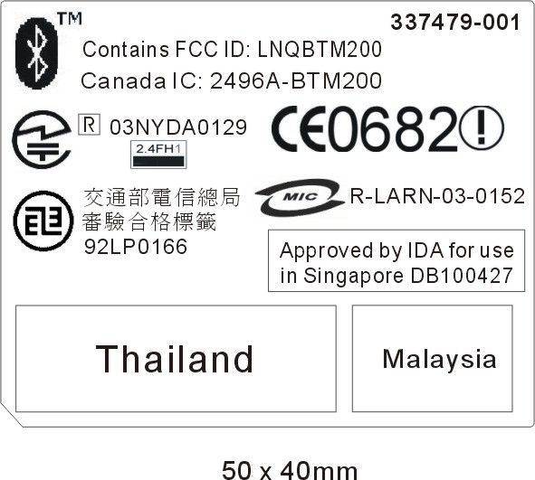
American Telecommunications Certification Body Inc. 6731 Whittier Ave, McLean, VA 22101 October 1, 2003 RE: FCC ID: CNTPP3006_ATCB000808 Attention: Mary Ellen Clayton I have a few comments on this Application. Documentation 1. Please provide the letter of authorization form the manufacturer giving authority for CKC to act as agent for this LMA. 2. Please note that this is an LMA application. In recent TCB council meetings with the FCC they have stated that external photos of the host device need to be provided for an LMA approval. Please provide external photos of the host in which this transmitter will be used. - 3. Please note that on page 1 of the internal photos there is an rf shield covering part of the circuitry. Please remove this shield and provide photos of the circuitry underneath this shield. 4. Please note that on the FCC ID sample label exhibit you have two labels. One identified as MOW has the FCC ID number, and one identified as ROW is without the FCC ID number. Please explain. 5. Please note that the host contains a Bluetooth transmitter. It is assumed because there is no data on this Bluetooth transmitter that it is an already approved device. If the device is a USB type peripheral, nothing need be done. However, if it is an approved Bluetooth module, it is required that a label stating “Contains TX FCC ID:XXXX” (or similar) be on the host. While not necessarily part of this application, evidence that this label is placed on the host as required by the FCC needs to be provided. Please provide evidence that the host is properly marked for this Bluetooth transmitter (i.e. the Bluetooth label mentioned in the documentation). 6. Please note that the manual states that regulatory information can be found in the “Documentation Library CD”. While this approach is OK, the regulatory information must still be provided for review at the time of certification. Please provide the necessary documentation from this CD that addresses all appropriate FCC statements and warnings. These include the rf exposure statement for SAR compliance and the 15.21 non-modification statement etc. 7. Please note that there appears to be more than ample room on the host to accommodate the 2-condition statement of 15.19. Please provide the sample 2-condition statement that is to be on the device. Alternately, please explain how this device adequately meets the exemption requirements of 15.19(a)(5). EMC report 8. FYI – no action needed. Please note that there are no limits for antenna terminal conduction testing for receivers above 960MHz. As such, this test (15.111) is not required. 9. Please note that the FCC accepted test procedure for DTS devices of Oct 2002 states that the proper resolution bandwidth for making the 6dB bandwidth measurements is 100kHz with the video bandwidth equal to or greater than the resolution bandwidth. Please note that in the plot on pages 12 through 21 of the report you show resolution bandwidths of 5MHz and video bandwidths of 3MHz (video bandwidth less than resolution BW). While the 6dB bandwidth of the 802.11b device is greater than that required, measurements should be done in accordance with the accepted FCC procedures. Please explain why measurements were made that were not in accord with the established FCC accepted procedures. 10. Please note that your PPSD (Power Spectral Density) was not measured in accordance with accepted FCC procedures. While the device may be compliant, the proper measurement of PPSD is with a resolution BW of 3k, a video BW of 3K and a sweep time of span/3k). Your span exceeds 100MHz. In order to measure the PPSD within any 3kHz band as required by the FCC, the proper sweep time for your setup would then be in excess of 33,000 seconds. Your sweep time is listed as only 27.3 seconds and thus is not properly measuring the power density in a 3kHz band and may mot be reporting an accurate PPSD. Please provide PPSD measurements in accordance z Page 2 October 1, 2003 with the required FCC accepted procedures. Alternately, please explain how a 27 sec sweep with a span of 100MHz is capable of properly measuring the FCC required PPSD in a 3 kHz window. 11. Please note that your “Peak Output Power” procedure listed on page 49 of the report does not match that of the listed procedure on page 22 of the report. Please explain. SAR report 12. FYI – no action required. Please note that direct contact SAR cannot be evaluated by TCB’s. Also, please note that direct contact SAR (sometimes referred to as hand writs feet etc) is not needed nor desired in certifications by TCB. As the FCC does not require this information, it will be ignored in the review of the SAR report and will not be mentioned on the grant. 13. Please note that in the conversion of the original SAR report to the PDF file provided errors evidently occurred. Please note that on a number of pages a question mark (?) shows up rather than the proper term or value. Please correct the SAR report to appropriately show the proper terms and values. 14. Please note that TCBs must use 1528 and OET 65C. Section 5.2 of the SAR report states that 1528 section 7 was used “where appl…
Text truncated - open the document above for the full version.
Contact Information
Applicant
Richard P Tarsio(US Canada Technical Regulations)
Technical Contact
CKC Laboratories, IncMary E Clayton
[email protected]209-966-5240
5473A Clouds Rest · Mariposa, California · United States
Test Firm
CKC Laboratories, Inc.Steve Behm
Technical Specifications
| # | Rule Parts | Frequency Range | Power Output |
|---|---|---|---|
| 1 | 15C | 2.41 GHz - 2.46 GHz | 46.00 mW |
Other Applications from HP Inc.
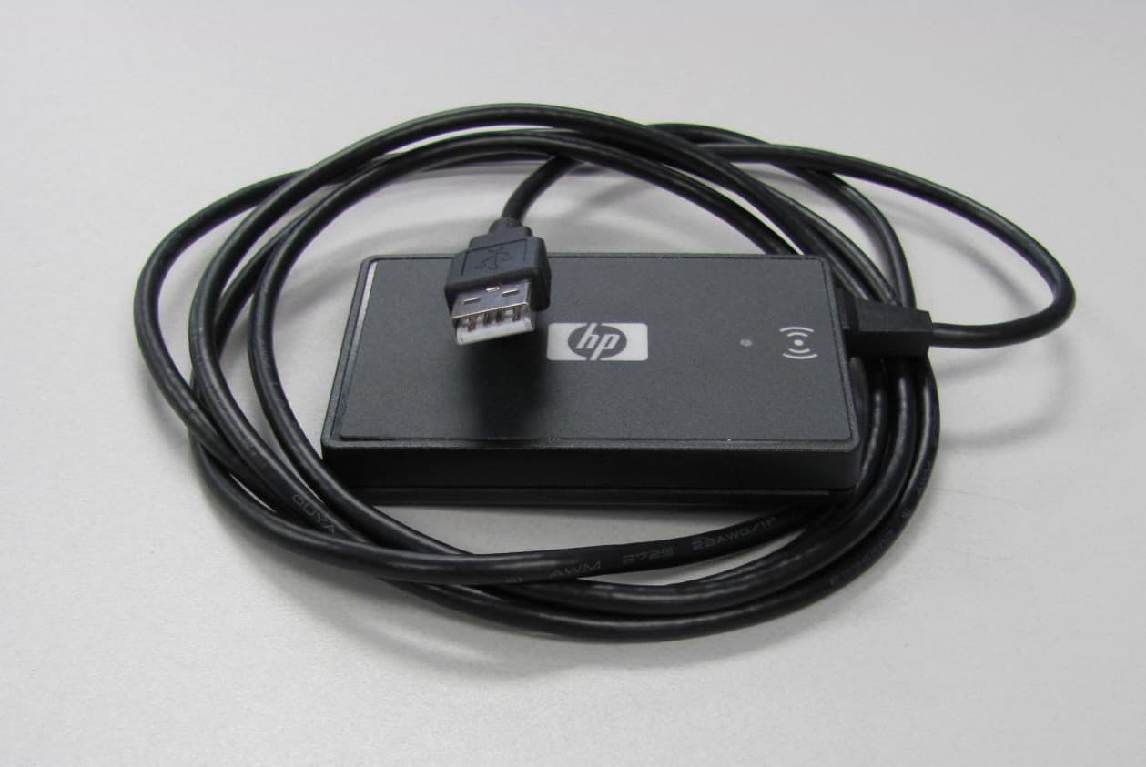
CNTBOISB110600
Jul 17, 2011Multi-Protocol RFID Reader
Equipment Class
DXX - Part 15 Low Power Communication Device Transmitter
CNTWM3B2915ABG
Dec 19, 2004Intel Mini PCI Type 802.11ABG WLAN Adapter
Equipment Class
NII - Unlicensed National Information Infrastructure TX
CNTPP2170SIL
Apr 08, 2004Laptop with WLAN and Bluetooth
Equipment Class
DTS - Digital Transmission System
CNTWM3B2200BGA
Feb 29, 2004Laptop w/ Intel 802.11 BG Wireless LAN Adapter
Equipment Class
DTS - Digital Transmission System
CNTHSTNN-I01C
Nov 13, 2003Notebook PC with Built-in Wireless
Equipment Class
DTS - Digital Transmission System