CNTWPE3012Multiport Wireless LAN Device
HP Inc.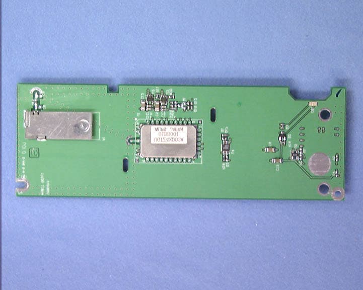
Click to zoom
Application Details
- Equipment Class
- DSS - Part 15 Spread Spectrum Transmitter
- Date of Grant
- Jul 22, 2001
- Application Purpose
- Original Equipment
- Date of Application
- Apr 25, 2001
- Equipment Note
- Multiport Wireless LAN Device
- Frequency Range
- 2401.00000000 - 2480.00000000
- Company
- HP Inc.
- Country
- United States
Documents & Files
Document Text
Text extracted from the exhibit documents filed with the FCC. Open a document above to read the original.
Users Manual
User’s Manual - Regulatory Notice In some situations or environments, the use of wireless devices may be restricted by the proprietor of the building or responsible representatives of the organization. Such restrictions may apply when: • Using the wireless equipment on airplanes, or • The risk of interference to other devices or services is perceived or identified as harmful. If you are uncertain of the policy that applies on the use of wireless equipment in a specific organization or environment (e.g. airports), you are encouraged to ask for authorization to use this device prior to turning on the equipment. U.S. Regulatory Statement ! Warning: Exposure to Radio Frequency Radiation The radiated output power of this device is far below the FCC radio frequency exposure limits. Nevertheless, the device should be used in such a manner that the potential for human contact during normal operation is minimized. In order to avoid the possibility of exceeding the FCC radio frequency exposure limits, human proximity to the antenna should not be less than 20 cm (8 inches) during normal operation. Canadian Regulatory Statement To prevent radio interference to the licensed service, this device must be operated indoors only and should be kept away from windows to provide maximum shielding. European Union Notice 0682 Products with the CE marking comply with the R&TTE Directive (1999/5/EC), EMC Directive (89/336/EEC) and the Low Voltage Directive (73/23/EEC) issued by the Commission of the European Community. Compliance with these directives implies conformity to the following European Norms (in parentheses are the equivalent international standards and regulations): • EN 55022 (CISPR 22) – Electromagnetic Interference • EN55024 (IEC61000-4-2, 3, 4, 5, 6, 8, 11) – Electromagnetic Immunity • EN61000-3-2 (IEC61000-3-2) – Power Line Harmonics • EN61000-3-3 (IEC61000-3-3) – Power Line Flicker • EN 60950 (IEC 60950) – Product Safety • ETS 300 328 – Technical requirements for radio equipment • ETS 300 826 – General EMC requirements for radio equipment This product may be used in the following EU and EFTA countries: Austria, Belgium, Denmark, Finland, France, Germany, Greece, Iceland, Ireland, Italy, Liechtenstein, Luxembourg, Netherlands, Norway, Portugal, Sweden, Switzerland and United Kingdom.
Block Diagram
Baseband DSP Data Enable USB Data 13 MHz Demod D/A RF Synthesizer LNA LNA PA PA 1.5 MHz 2.5 MHz X2 2400.5 –2478.5 MHz 2399.5 –2477.5 MHz Baseband Regulator PA Regulator 2402 –2480 MHz Block Diagram –BluetoothMultiport Module by Compaq
Cover Letter(s)
Compaq Computer Corporation 20555 SH 249 P.O. Box 692000 Houston, TX 77070-2698 Houston, TX 77269-2000 Tel 713-370-0670 TM - Bluetooth is a trademark owned by the Bluetooth SIG, Inc 25 April, 2001 Federal Communications Commission Equipment Authorization Division Applications Processing Branch 7435 Oakland Mills Road Columbia, MD. 21046 Dear Sir or Madam, In accordance with FCC Public Notice DA 00-1407, PART 15 UNLICENSED MODULAR TRANSMITTER APPROVAL Released: June 26, 2000, Compaq is requesting approval of the Compaq PE3012 Multiport Wireless LAN Module (proposed FCC ID: CNTWPE3012) as an unlicensed modular transmitter. The PE3012 Multiport Module by Compaq is a Bluetooth TM radio which mounts on the Multiport of an appropriately equipped computer. Multiport is a Compaq proprietory interface currently incorporated in Notebook computers. The proprietary interface uses a USB bus for data communications. The PE3012 module consists of a PCB, a plastic cover, and screws to secure the board to the interface port Mounting surface. The PE3012 PCB contains a Bluetooth module, an antenna, and signal conditioning components. The Bluetooth module is a self contained, surface mount transceiver which is covered with its own RF shield. The antenna on the PCB is not shielded. The USB D+ and D- data lines into the Bluetooth module are protected by a PI5C3305 bus switch which defaults to a high impedance state when disconnected. The Bluetooth module uses Cambridge Silicon Radio’s BC01B-USB chip. When the chip can no longer receive data, it drives the input data lines to 0V. All of the data received over the USB interface is controlled inside the BC01B-USB by the memory management unit block. The power supply input to the PE3012 Multiport Module by Compaq is regulated by two MAXIM 8887 voltage regulators (one for the PA circuitry and one for the baseband and other RF circuitry). The antenna for the PE3012 Multiport Module by Compaq is permanently attached to the module PCB which also carries the Bluetooth transceiver. There are no cables associated with the RF transmission. The PE3012 Multiport Module by Compaq is mounted on the outside of the Multiport equipped computer, hence it is never tested “inside” a device. The device was tested on a typical platform, the length of power supply and data lines during testing are representative of Multiport applications. No ferrites were used on the data or power supply lines when testing the PE3012 Multiport Module by Compaq. The label for the PE3012 Multiport Module by Compaq is attached to the bottom of the module. A copy of the label artwork is provided with the submission material. There are no specific operational requirements for the PE3012 Multiport Module by Compaq with the exception that it is not allowed to be operated on an airplane. This constraint is detailed in the User’s Guide. Calculations are attached which demonstrate that the PE3012 Multiport Module by Compaq meets the RF Exposure requirements of Section 15.247(b)(4). A copy of instructions regarding RF exposure which are in the User’s Guide is provided with the submission material. Respectfully Submitted, E. Joseph Sharkey Compaq Computer Corporation
Cover Letter(s)
Compaq Computer Corporation20555 SH 249 P.O. Box 692000Houston, TX 77070-2698 Houston, TX 77269-2000Tel 713-370-0670 June 14, 2001 Federal Communications Commission Laboratory Division 7435 Oakland Mills Road Columbia, MD 21046 Confirmation Number: EA100772 Subject: Confidentiality for Compaq Series PE3012, FCC ID: CNTWPE3012 The subject package has been submitted to the FCC for a Grant of Authorization. The following exhibit is to be considered confidential and therefore we re requesting confidentiality. SC HEMA TIC The document has been given to Compaq for use for this program under a confidentiality agreement by Ambit Corporation. All appropriate fees have been submitted and paid for in advance. If you have any questions regarding the submission or this request please contact me at 281-927-3603. Sincerely, Joe Sharkey Manager, EMC Test Services Compaq EMC Services
ID Label/Location Info
FCC Label Location – PE3012
ID Label/Location Info
Proposed WPE3012 Label 2.4FH8 FCC ID CNTWPE3012 CE 0682 Canada XXXXX Product of Taiwan Compaq Computer Corporation Model U98H009 Spare P/N 230336-001 Agency Series PE3012 This device complies with Part 15 of the FCC rules. Operation is subject to the following two conditions: (1) this device may not cause harmful interference, and (2) this device must accept any interference received, including interference that may cause undesired operation. FCC Registration Number: xxxxxxxxxxxxxxxxx
Internal Photos
Construction Photos View Page Assembly - Front 1 Assembly – Back 2 Plastics 3 PCB – Top 4 PCB – Back 5 Assembly – Installed 6 1 Assembly - Front 2 Assembly – Back 3 Plastics 4 PCB – Top 5 PCB – Back 6 Assembly – Installed
Operational Description
TM - Bluetooth is a trademark owned by the Bluetooth SIG, Inc COMPAQ COMPUTER CORPORATION Information Pursuant to application for Certification of the Compaq PE3012 Multiport Wireless LAN Module (proposed FCC ID: CNTWPE3012) as an intentional radiator subject to the provisions of CFR 47 Part 15 Sub Part C. Product Description The PE3012 Multiport Module by Compaq is a Bluetooth TM radio which mounts on the Multiport of an appropriately equipped computer. Multiport is a Compaq proprietary interface currently incorporated in Notebook computers. The proprietary interface uses a USB bus for data communications. The PE3012 module consists of a PCB, a plastic cover, and screws to secure the board to the interface port Mounting surface. The PE3012 PCB contains a Bluetooth module, an antenna, and signal conditioning components. The Compaq Multiport is a Compaq proprietary port based on the USB interface. The port offers the functionality of USB with a snap on footprint providing ease of design and use on Compaq products. The port is currently incorporated in one series of Compaq Notebook PCs. Section 15.203 The antenna for the module is permanently attached during manufacturing. The antenna is soldered to a PCB. In the module’s intended use, the antenna is inaccessible to the user, with the entire PCB covered by a plastic cover. Section 15.204 The antenna is a Yagi manufactured by RangeStar, Model 100929. The gain in reference to an isotropic radiator is +3 dBi. Section 15.247(a) Pseudorandom Frequency Hopping Sequence - 79 channels, each separated by 1 MHz, are available for the system. Five hopping sequences are defined for Bluetooth: • A page hopping sequence with 32 unique wake-up frequencies distributed equally over 79 MHz, with a period length of 32; • A page response sequence covering 32 unique response frequencies that all are in an one-to-one correspondence to the current page hopping sequence. The master and slave use different rules to obtain the same sequence; • An inquiry sequence with 32 unique wake-up frequencies distributed equally over 79 MHz, with a period length of 32; • An inquiry response sequence covering 32 unique response frequencies that all are in an one-to-one correspondence to the current inquiry hopping sequence. • A channel hopping sequence which has a very long period length, which does not show repetitive patterns over a short time interval, but which distributes the hop frequencies equally over the 79 MHz during a short time interval; TM - Bluetooth is a trademark owned by the Bluetooth SIG, Inc The inquiry and inquiry response sequences always utilize the Bluetooth GIAC LAP as lower address part and the DCI as upper address part in deriving the hopping sequence, even if it concerns a DIAC inquiry. The selection scheme consists of two parts: • selecting a sequence; • mapping this sequence on the hop frequencies; The mapping from the input to a particular hop frequency is performed in the selection box. (See Figure 1) Basically, the input is the native clock and the current address. In CONNECTION state, the native clock (CLKN) is modified by an offset to equal the master clock (CLK). Only the 27 MSBs of the clock are used. In the page and inquiry sub states, all 28 bits of the clock are used. However, in page sub state the native clock will be modified to the master’s estimate of the paged unit. Figure 1. General block diagram of hop selection scheme The address input consists of 28 bits, i.e., the entire LAP and the 4 LSBs of the UAP. In CONNECTION state, the address of the master is used. In page sub-state the address of the paged unit is used. When in inquiry sub state, the UAP/LAP corresponding to the GIAC is used. The output constitutes a pseudo-random sequence, covering 79 hops. The selection scheme chooses a segment of 32 hop frequencies spanning about 64 MHz and visits these hops once in a random order. Next, a different 32-hop segment is chosen, etc. In case of the page, page scan, or page response sub states, the same 32-hop segment is used all the time (the segment is selected by the address; different units will have different paging segments). In connection state, the output constitutes a pseudorandom sequence that slides through the 79 hops. In the hop selection kernels for the 79 hop system (Figure 2), the X input determines the phase in the 32-hop segment, whereas Y1 and Y2 selects between master-to-slave and slave-to-master transmission. The inputs A to D determine the ordering within the segment, the inputs E and F determine the mapping onto the hop frequencies. The kernel addresses a register containing the hop frequencies. This list should be created such that first all even hop frequencies are listed and then all odd hop frequencies. In this way, a 32-hop segment spans about 64 MHz. TM - Bluetooth is a trademark owned by the Bluetooth SIG, Inc Figure 2. Block diagram of hop selection kernel for the 79-hop system The selection procedure consists of an addition, an XOR operation, a permutation operation, an addition, and finally a register selection. In the remainder of this chapter, the notation A i is used for bit i of the BD_ADDR. The first addition operation only adds a constant to the phase and applies a modulo 32 operation. For the page hopping sequence, the first addition is redundant since it only changes the phase within the segment. However, when different segments are concatenated (as in the channel hopping sequence), the first addition operation will have an impact on the resulting sequence. Let Z’ denote the output of the first addition. In the XOR operation, the four LSBs of Z’ are modulo-2 added to the address bits A 22-19 . The permutation operation involves the switching from 5 inputs to 5 outputs for the 79 hop system in a manner controlled by the control word. The permutation or switching box consists of 7 stages of butterfly operations. The addition operation only adds a constant to the output of the permutation operation. As…
Text truncated - open the document above for the full version.
RF Exposure Info
TM - Bluetooth is a trademark owned by the Bluetooth SIG, Inc Maximum Permissible Exposure Assessment For the Compaq PE3012 Multiport Bluetooth TM Module In accordance with FCC Report And Order 96-326 Adopted August 1, 1996 SAR Calculations for Compaq PE3012 PE3012 Maximum Transmit Power(Pt) = +10 dBm PE3012 Max Antenna Gain (Gt) = +4dBi PE3012 EIRPmax = Pt + Gt = 14 dBm = 25.1 mW The worst case transmit duty cycle for a data only Bluetooth device would be transmission of DH5 packets in a piconet with one other user. In that case, the transmit duty cycle would be 76.1%. The average power for DH5 packets would be: EIRPmax X .761 = 19.12 mW = +12.81 dBm The specification for SAR is 1mW/cm2. If there is 12.81 dB of space loss, the signal from PE3012 would be 0 dBm or 1 mW. The range 12.81 dB of space loss at 2402 MHz (lowest Bluetooth frequency) can be calculated by the equation: Ls = [(4πd)/λ] 2 Where λ = wavelength = c/f and d=range in meters For Ls = 12.81 and f=2402 MHz, d= 1.71 inches The incident signal will not be greater than 1 mW unless the body is within 1.71 inches of the PE3012 antenna. When the Compaq notebook is in use, the PE3012 antenna is at the top of the display within the multiport module, and the typical distance to the human body (hands on the keyboard) is 8 inches. It would be unnatural and uncomfortable to hold one’s hand within 1.71 inches of the PE3012 antenna continuously. Therefore, it is reasonable that the allowed SAR levels will not be exceeded. Conclusion: The MPE distance for the Compaq PE3012 is below the minimum required distance (20 centimeters) for a mobile device. A statement will appear in the user manual that informs the users to maintain a minimum distance of 20 centimeters between the modem antenna and all persons during device operation.
RF Exposure Info
SAR Calculations for Bluelight Bluelight Maximum Transmit Power(Pt) = +8 dBm Bluelight Max Antenna Gain (Gt) = +5.5 dBi Bluelight EIRPmax = Pt + Gt = 13.5 dBm = 22.4 mW The worst case transmit duty cycle for a data only Bluetooth device would be transmission of DH5 packets in a piconet with one other user. In that case, the transmit duty cycle would be 76.1%. The average power for DH5 packets would be: EIRPmax X .761 = 17.05 mW = +12.32 dBm The specification for SAR is 1mW/cm2. If there is 12.32 dB of space loss, the signal from Bluelight would be 0 dBm or 1 mW. The range 12.32 dB of space loss at 2402 MHz (lowest Bluetooth frequency) can be calculated by the equation: Ls = [(4πd)/λ] 2 Where λ = wavelength = c/f and d=range in meters For Ls = 12.81 and f=2402 MHz, d= 1.58 inches So, the incident signal will never be greater than 1 mW unless the body is within 1.58 inches of the Bluelight antenna. When the Compaq notebook is in use, the Bluelight antenna is at the top of the display within the multiport module, and the typical distance to the human body (hands on the keyboard) is 8 inches. It would be unnatural and uncomfortable to hold one’s hand within 1.58 inches of the Bluelight antenna continuously. Therefore, it is unlikely that the allowed SAR levels will be exceeded.
RF Exposure Info
SAR Calculations for Bluelight Bluelight Maximum Transmit Power(Pt) = +8 dBm Bluelight Max Antenna Gain (Gt) = +5.5 dBi Bluelight EIRPmax = Pt + Gt = 13.5 dBm = 22.4 mW The worst case transmit duty cycle for a data only Bluetooth device would be transmission of DH5 packets in a piconet with one other user. This is shown as the bottom row in Figure 2.2 below. For DH5 packets the transmitter transmits across five 625 microsecond slots minus a guard band of 259 microseconds. The transmission is followed by a 625 microsecond receive slot. The transmission duty cycle (Tdc) for this case can be calculated as: Tdc = (625 * 5) – 259 625 * 6 Tdc = 76% The average power for DH5 packets would be: EIRPmax X .76 = 17.0 mW = +12.3 dBm Using the equation for an estimate of distance from the antenna from OET Bulletin 65: R = (EIRP/4πS) 1/2 Where, R= distance to the center of radiation of the antenna in cm S = power density in mW/cm 2 (1 mW/cm 2 used for Bluelight) EIRP = effective isotropically radiated power in mW (17 for Bluelight) R = 1.16 cm Therefore the 1 mW/cm2 requirement is not exceeded unless the body is less than 1.16 cm from the Bluelight antenna. In normal operation of Bluelight, the body will be more than 20 cm from the antenna.
Test Report
COMPAQ COMPUTER CORPORATION COMPAQ CONFIDENTIAL ELECTROMAGNETIC COMPATIBILITY (EMC) TEST REPORT Project Number: 01145 DATE OF REPORT: April 13, 2001 Product Series Number: PE3012 Product: Multiport Wireless Bluetooth Module “Accredited by the National Voluntary Laboratory Accreditation Program for the specific scope of accreditation under Lab Code 200058-0.” NOTICE: This report may not be used to claim product endorsement by NVLAP or any agency of the United States Government NOTICE: This NVLAP accreditation is valid only for radiated and conducted emission test results This report may not be reproduced except in full without the written approval of Compaq EMC Services Table of Contents 1.0 SCOPE.............................................................................................................................................................1 2.0 COMPLIANCE STATEMENT.....................................................................................................................1 3.0 DEVICE UNDER TEST/PRODUCT DESCRIPTION...............................................................................1 4.0 TEST LOCATION.........................................................................................................................................1 5.0 CALIBRATION..............................................................................................................................................1 MEASUREMENT UNCERTAINTIES....................................................................................................................1 6.0 MEASUREMENT EQUIPMENT.................................................................................................................2 7.0 EQUIPMENT UNDER TEST CONFIGURATION - EMISSIONS...........................................................3 8.0 RADIATED EMISSION TEST.....................................................................................................................4 8.1 TEST CONFIGURATION...........................................................................................................................4 8.2 TEST CONDITION......................................................................................................................................4 8.3 FREQUENCY RANGE................................................................................................................................4 8.4 TEST PROCEDURE....................................................................................................................................4 8.5 TEST DATA 30 MHZ – 1 GHZ & ABOVE 1 GHZ (DIGITAL DEVICE)..........................................................5 8.6 TEST DATA 30 MHZ – 1 GHZ & ABOVE 1 GHZ (INTENTIONAL RADIATOR).............................................6 8.7 MAXIMUM EMISSION CONDITION.......................................................................................................7 9.0 CONDUCTED EMISSION TEST – POWER LINE...................................................................................8 9.1 TEST CONFIGURATION...........................................................................................................................8 9.2 TEST CONDITION......................................................................................................................................8 9.3 FREQUENCY RANGE................................................................................................................................8 9.4 TEST PROCEDURE....................................................................................................................................8 9.5 TEST DATA.................................................................................................................................................9 9.6 MAXIMUM EMISSION CONDITION.....................................................................................................10 10.0 CONDUCTED EMISSION TEST – ANTENNA.......................................................................................11 10.1 TEST CONFIGURATION.........................................................................................................................11 10.2 TEST CONDITION....................................................................................................................................11 10.3 FREQUENCY RANGE..............................................................................................................................11 10.4 TEST PROCEDURE..................................................................................................................................11 11.0 DATE OF TEST............................................................................................................................................18 12.0 TEST PERSONNEL.....................................................................................................................................19 CONFIDENTIAL COMPAQ COMPUTER CORPORATION EMC TEST REPORT - Project Number 01145 Series Number: PE3012 Page 1 of 19 01145.DOC 4/25/01 1.0 SCOPE This document details the test results and the measurement procedures and equipment in use at the time the device described in section 3.0 was tested for radio frequency emissions. 2.0 COMPLIANCE STATEMENT This product has been tested and found to comply with the applicable limits of CFR 47 Part 15 Subparts B and C and CISPR 22; (CNS13438; AS/NZS3548; EN55022). 3.0 DEVICE UNDER TEST/PRODUCT DESCRIPTION Model: Compaq/Ambit U98H011.00 Form Factor: Multiport Module FCC ID: CNTWPE3012 (proposed) Serial Number: CAT000030556 Detail: BLUETOOTH Wireless LAN Module for Multiport equipped PC. 4.0 TEST LOCATION Tests were performed at COMPAQ COMPUTER CORPORATION Emission Control Laboratory located at 10320 Rodgers Road, Houston, Texas. Information regarding this test site is currently on file with the FCC. This test site meets the requirem…
Text truncated - open the document above for the full version.
Test Report
CompaqJune 14, 2001 COMPAQ COMPUTER CORPORATION Emission Test Report For Series PE3012 Date: June 14, 2001 Compaq Compute r Corporat ion Lab Address:Mailing Address: 10320 Rodgers Road20555 SH 249, PO Box 692000 Houston, Texas 77070MS 510101 Houston, Texas 77269- 2000 “Accredited by the National Voluntary Laboratory Accreditation Program for the specific scope of accreditation under Lab Code 200058-0.” PE3012 This document has been compiled as the response to the following FCC inquiry pursuant to certification of the Compaq PE3012 intentional radiator (FCC ID: CNTWPE3012). From: OET [mailto:[email protected]] Sent: Tuesday, June 05, 2001 1:20 PM To: Sharkey, Joe Subject: To: E. Sharkey, null From: Joe Dichoso [email protected] FCC Application Processing Branch Re: FCC ID CNTWPE3012 Applicant: Compaq Computer Corporation Correspondence Reference Number: 19518 731 Confirmation Number: EA100772 1)Confidential letter 2)Block diagram with oscillators and frequencies. 3)Schematic 4)Provide a photo to verify antenna and antenna location. The filing lists the antenna gain as 3 dBi while the RF safety exhibit indicates 4 dBi. Please explain/correct. 5)The device is not a module but is a computer peripheral transceiver not intended for use within other devices but is attached to the outside of a laptop. The device is a composite device( a computer peripheral and a transmitter). Indicate authorization for the computer peripheral portion. If it will be Certified, file another application under the same FCC identifier as a composite application. If it will be DOC approved, indicate so and correct the label for DOC label requirements. This Bluetooth transmitter is a Frequency Hopping Spread Spectrum(FHSS) transmitter in the data mode and a Hybrid transmitter in the acquisition mode. Provide the following with regard to the device operating in the data mode(FHSS) Section 15.247(a)1. 6)The first pseudorandom sequence on page 4 of the technical description is not pseudorandom. The sequence shows that the next hop occurs in a fixed interval. Please explain. 7)The transmitter cannot coordinate its hopping sequence with the hopping sequence of other transmitters, or vice versa, for the purpose of avoiding the simultaneous occupancy of individual hopping frequencies by multiple transmitters. The technical description indicates that no coordination occurs between transmitter outside a piconet. How does the device meet the non-coordination requirement for multiple transmitter within a piconet? Provide the following information with regard to the device operating in the page and inquiry mode under the Spread spectrum Hybrid requirements in Section 15.247(f) and Section 15.247(a)1. Hybrid spread spectrum transmitters are authorized under Section 15.247(f) of the Rules. The technical requirements in that Section require: 8)A minimum processing gain. The processing gain may be demonstrated as a combination of gain from the spreading/despreading function (using, for instance, a jamming margin test- see Section 15.247(e)(2)) and the gain from the hopping function, equal to 10log(number of hopping channels). A copy of the Processing gain measurement can be found at the end of the Rulemaking Order for DSSS transmitters and can be found at www.fcc.gov/Bureaus/Engineering_Technology/Orders/1997/fcc97114.txt 9)An average time of channel occupancy limit. 10)A power spectral density limit. The power spectral density limit is found in Section 15.247(d). Please note that these hopping channels in the page/inquiry must also comply with the requirements set forth and described in Section 15.247(a)(1). The requirements are: 11)A Minimum channel separation. 12)Pseudorandom hop sequence. 13)Use of each frequency equally on average. 14)Receiver matching bandwidth and synchronization. CompaqJune 14, 2001 2) Block diagram with oscillators and frequencies. "block diagram.doc" 3) Schematic Schematic Diagram - PE3012 4) Provide a photo to verify antenna and antenna location. The filing lists the antenna gain as 3 dBi while the RF safety exhibit indicates 4 dBi. Please explain/correct. The peak measured gain of the antenna has been 5.5 dBi. It is a planar inverted F antenna (PIFA). 5)The device is not a module but is a computer peripheral transceiver not intended for use within other devices but is attached to the outside of a laptop. The device is a composite device( a computer peripheral and a transmitter). Indicate authorization for the computer peripheral portion. If it will be DOC approved, indicate so and correct the label for DOC label requirements. CompaqJune 14, 2001 As a computer peripheral the device will be self declared. An FCC Grant is being sought for the intentional radiator under Part 15 Section C. The revised “proposed label” is attached below. 6) The first pseudorandom sequence on page 4 of the technical description is not pseudorandom. The sequence shows that the next hop ocurs in a fixed interval. Please explain. The first sequence show n on page 4 is for page scan and inquiry scan. This particular sample set was based upon an initial clock of 0x0000000 and a ULAP of 0x000000000 w hich is unlikely. The second and third sample sets in the Bluetooth specification have different ULAP values (more realistic) and show the randomness of the page and inquiry scan. Attached is the second sample set with a clock start of 0x0000000 and a ULAP of 0x2a9ef25. secondset.doc 7) The transmitter cannot coordinate its hopping sequence with the hopping sequence of other transmitters, or vice versa, for the purpose of avoiding the simultaneous occupancy of individual hopping frequencies by multiple transmitters. The technical description indicates that no coordination occurs between transmitter outside a piconet. How does the device meet the non- coordination requirement for multiple transmitter within a piconet? Inside a piconet only one of the member's transmitters is active at any given time, so no frequency coordination is ne…
Text truncated - open the document above for the full version.
Test Report
PE3012 Module COMPAQ June 14, 2001 Average time of occupancy for inquiry and page modes. Inquire Mode There are 32 Channels used in the inquiry mode (Figure 1). In a 13 second span, there are three blocks of transmission on a channel, each block spanning 2.553 seconds (Figure 2). During …
Text truncated - open the document above for the full version.
Contact Information
Applicant
Richard P Tarsio(US Canada Technical Regulations)
Test Firm
Hewlett-Packard CompanyJohn Hirvela
Technical Specifications
| # | Rule Parts | Frequency Range | Power Output | Tolerance |
|---|---|---|---|---|
| 1 | 15C | 2.40 GHz - 2.48 GHz | 10.00 mW | ppm |
Other Applications from HP Inc.
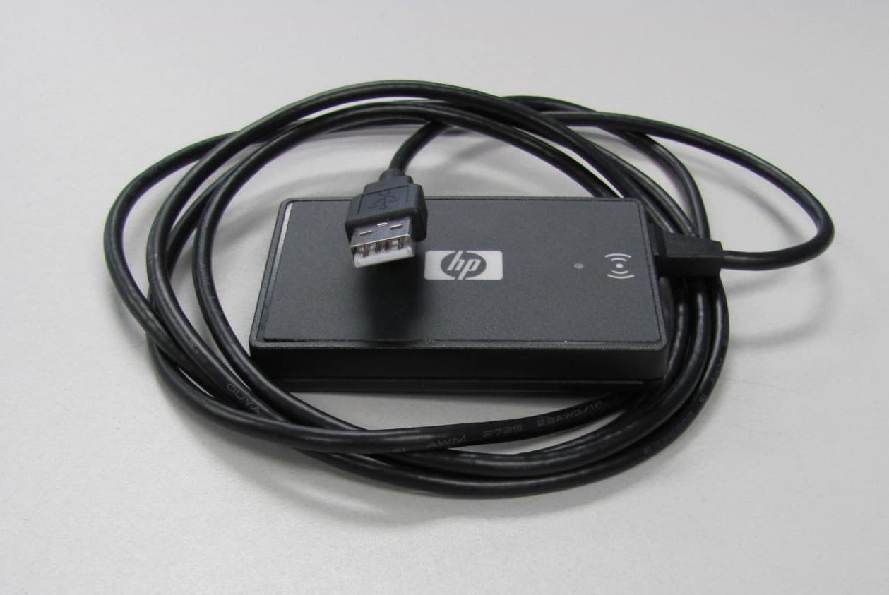
CNTBOISB110600
Jul 17, 2011Multi-Protocol RFID Reader
Equipment Class
DXX - Part 15 Low Power Communication Device Transmitter
CNTWM3B2915ABG
Dec 19, 2004Intel Mini PCI Type 802.11ABG WLAN Adapter
Equipment Class
NII - Unlicensed National Information Infrastructure TX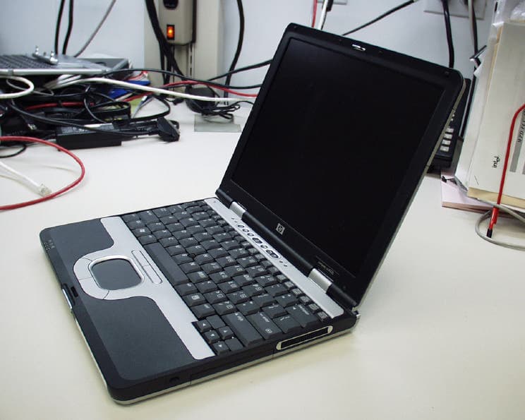
CNTPP2170SIL
Apr 08, 2004Laptop with WLAN and Bluetooth
Equipment Class
DTS - Digital Transmission System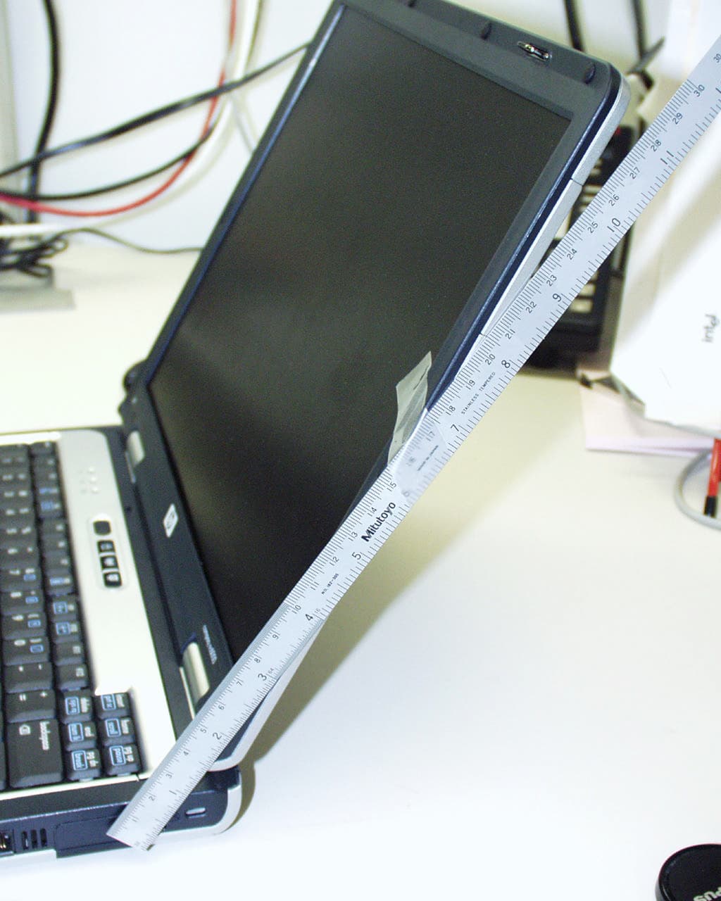
CNTWM3B2200BGA
Feb 29, 2004Laptop w/ Intel 802.11 BG Wireless LAN Adapter
Equipment Class
DTS - Digital Transmission System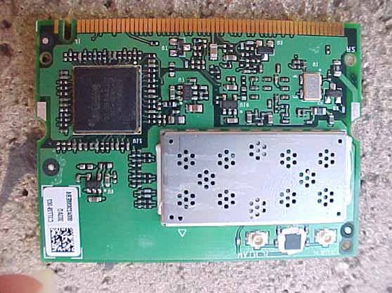
CNTHSTNN-I01C
Nov 13, 2003Notebook PC with Built-in Wireless
Equipment Class
DTS - Digital Transmission System