CSQHG200BHomeGuard Standard Transmitter, Model HG200B
BI Incorporated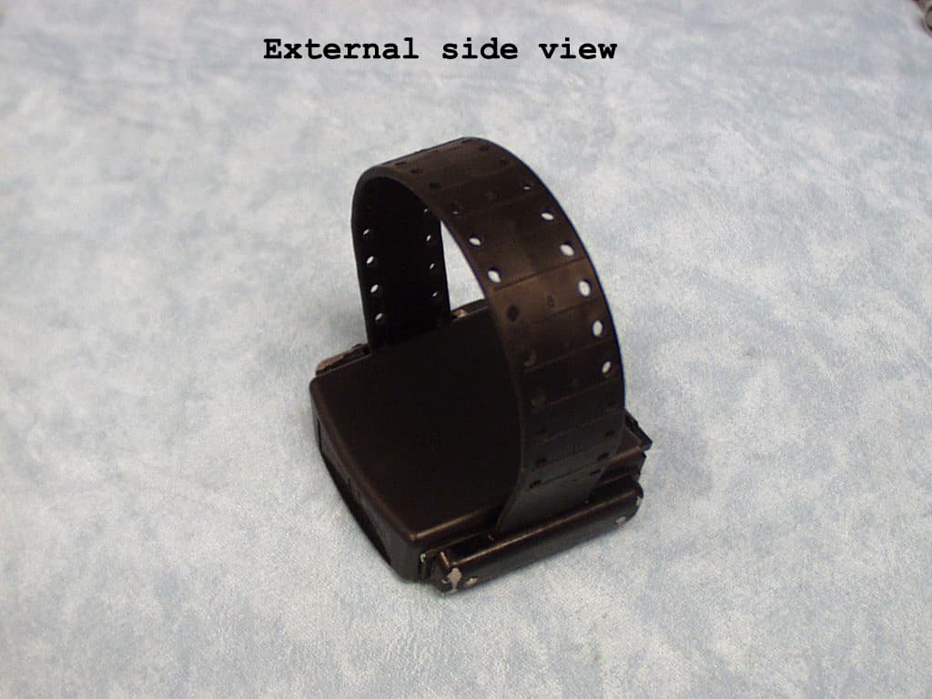
Click to zoom
Application Details
- Equipment Class
- DSC - Part 15 Security/Remote Control Transmitter
- Date of Grant
- Dec 09, 2001
- Application Purpose
- Original Equipment
- Date of Application
- Dec 09, 2001
- Equipment Note
- HomeGuard Standard Transmitter, Model HG200B
- Frequency Range
- 314.20000000 - 314.20000000
- Company
- BI Incorporated
- Country
- United States
Documents & Files
Document Text
Text extracted from the exhibit documents filed with the FCC. Open a document above to read the original.
Users Manual
BI HomeGuard 200™ Officer’s Reference Manual BI Part Number 8-90-00089-1 © 2001 BI Incorporated Revision A 8-90-00089-1, Revision Ai Preface Preface Notice HomeGuard 200 Officer’s Reference Manual Copyright © 2001 by BI Incorporated All Rights Reserved Printed in USA BI prepared this manual for use by BI customers only. All com- ments concerning the contents of this manual should be directed to BI’s Marketing Department, 6400 Lookout Road, Boulder, CO 80301, USA. No part of this work covered by copyright may be reproduced in any form either graphically, electronically, mechanically; including photo- copying, recording, taping, or storage in an information retrieval system without prior written permission from BI. Trademarks and Patents The following are registered trademarks of BI Incorporated: • BI • BI logo • BI HomeGuard 200 Receiver • BI HomeGuard 200 Transmitter • BI HomeGuard Drive-BI • BI GuardWare Host System • BI 9010 Transmitter • BI K2 Host System • BI HES 600 Host System • BI Sobrietor Document History This document was created using Adobe FrameMaker 6 and Paint- Shop Pro 7. The body text is the Utopia typeface. This is Revision A, September 2001, BI Part No. 8-90-00089-1. HomeGuard 200 Officer’s Reference Manual ii8-90-00089-1, Revision A Technical Support For help related to client enrollment and schedules, reporting, and host computer functions call your monitoring center. BI Incorporated has two monitoring centers, East and West. For technical assistance with BI Products, call BI Technical Sup- port at (800) 241-9924 or your BI Account Service Representative. Purpose This manual provides an officer with the information necessary to implement and use HomeGuard 200 radio frequency monitoring prod- ucts. Scope The Officer’s Manual presents a tutorial for use of the HomeGuard 200 radio frequency monitoring system and a guide in acquainting cli- ents with home arrest procedures. It provides all information required to: • learn to use HomeGuard 200 Receiver, Transmitter, and Drive-BI • teach clients to use the HomeGuard 200 Receiver and Transmitter • install the HomeGuard 200 Receiver and Transmitter on site • set up monitoring requirements • troubleshoot and use the HomeGuard 200 products Note: Throughout this manual, the name HomeGuard 200 refers to the HomeGuard 200 radio frequency monitoring system. GuardCenter West BI Incorporated 6400 Lookout Road Boulder, CO 80301 USA (303) 218-1225 (800) 241-6768 FAX (303) 218-1250 GuardCenter East BI Incorporated One Citizen’s Plaza, Suite 501 Anderson, Indiana 46016 (765) 641-2496 (800) 825-1044 FAX (765) 649-3148 Preface 8-90-00089-1, Revision Aiii Preface Audience This manual is written for the attending officer who will train the client, set up the equipment, and monitor the client. United States FCC, Part 68 Compliance statement - This equipment complies with Part 68 of the FCC rules. On the bottom of the Receiver is a label that contains, among other information, the FCC registration number and ringer equivalence number (REN) for this equipment. If requested, this infor- mation must be provided to the telephone company. Jack type needed - The Receiver connects to the telephone network with a USOC RJ11C jack. An FCC compliant telephone cord and mod- ular plug is provided with this equipment. This equipment is designed to be connected to the telephone network or premises wiring using a com- patible modular jack which is Part 68 compliant. Explanation of the Ringer Equivalence Number (REN) - The REN is used to determine the quantity of devices which may be connected to the telephone line. Excessive RENs on the telephone line may result in the devices not ringing in response to an incoming call. In most, but not all areas, the sum of the RENS should not exceed five (5.0). To be cer- tain of the number of devices that may be connected to the line, as deter- mined by the total RENs, contact the telephone company to determine the maximum REN for the calling area. Temporary discontinuance of service - If the Receiver causes harm to the telephone network, the telephone company will notify you in advance that temporary discontinuance of service may be required. But if advance notice isn’t practical, the telephone company will notify the customer as soon as possible. Also, you will be advised of your right to file a complaint with the FCC if you believe it is necessary. Telephone company changes - The telephone company may make changes in its facilities, equipment, operations, or procedures that could affect the operation of the equipment. If this happens, the telephone company may provide advance notice in order for you to make the nec- essary modifications in order to maintain uninterrupted service. Disconnection in case of trouble and location of repair center - If trouble is experienced with the Receiver, please contact BI Incorpo- rated. If the equipment is causing harm to the telephone network, the telephone company may request that you disconnect the equipment from the network until the problem is resolved. HomeGuard 200 Officer’s Reference Manual iv8-90-00089-1, Revision A Repairs customers can make - There are no customer-serviceable parts inside the BI HomeGuard Receiver. (Power and phone cords are replaceable on the BI HomeGuard Receiver.) Prohibitions - Connection to party lines or to telephone company coin service is prohibited. Industry Canada NOTICE: The Industry Canada label identifies certified equipment. This certification means that the equipment meets telecommunications network protective, operational and safety requirements as prescribed in the Terminal Equipment Technical Requirements document(s). The Department does not guarantee the equipment will operate to the user’s satisfaction. Before installing this equipment, users should ensure that it is per- missible to be connected to the facilities of the local telecommunica- tions company. The equipment must also be installed using an acceptable method of connection. The…
Text truncated - open the document above for the full version.
ID Label/Location Info
FCC LABEL A drawing of the FCC label information that will be permanently affixed to the transmitter case is shown below. The location is on the bottom of the plastic case. Due to the small size of this device, it is not practical to place the complete label statement on the transmitter. Therefore, the information shown below is included in the instruction manual: This device complies with Part 15 of the FCC Rules. Operation is subject to the following two conditions: (1) this device may not cause harmful interference, and (2) this device must accept any interference received, including interference that may cause undesired operation. FCC ID: CSQHG200B CANADA XXXX XXXXX BI INCORPORATED 1.5" .5"
Test Report
File No. BC107362, Page 1 of 3 T ÜV PRODUCT SERVICE INC 5541 Central Avenue Boulder, Colorado 80301 Tel: 303 786 7999 Fax: 303 449 3004 Rev.No 1.0 EMC EMISSIONS - TEST REPORT Test Report No. BC107362-1 Issue Date November 8, 2001 Model / Serial No. HG200B / 485485 Product Type HG9010#2 Client BI Incorporated Manufacturer BI Incorporated License holder BI Incorporated Address 6400 Lookout Rd. Boulder, CO 80301 Test Criteria Applied FCC Part 15 Class B & 15.231e 47 CFR 15: Radio Frequency Devices Test Result PASS Test Project Number References BC107362 Total Pages Including Appendices: 20 Reviewed By : Todd Seeley Reviewed By : Robert Cresswell TÜV Product Service Inc is a subcontractor to TÜV Product Service, GmbH according to the principles outlined in ISO/IEC Guide 25 and EN 45001. TÜV Product Service Inc reports apply only to the specific samples tested under stated test conditions. It is the manufacturer's responsibility to assure that additional production units of this model are manufactured with identical electrical and mechanical components. TÜV Product Service Inc shall have no liability for any deductions, inferences or generalizations drawn by the client or others from TÜV Product Service Inc issued reports. This report is the confidential property of the client. As a mutual protection to our clients, the public and ourselves, extracts from the test report shall not be reproduced except in full without our written approval of TÜV Product Service. This report shall not be used by the client to claim product endorsement by NVLAP or any agency of the US government. TÜV Product Service Inc and its professional staff hold government and professional organization certifications and are members of AAMI, ACIL, AEA, ANSI, IEEE, NVLAP, and VCCI PRODUCT SERVICE File No. BC107362, Page 2 of 3 T ÜV PRODUCT SERVICE INC 5541 Central Avenue Boulder, Colorado 80301 Tel: 303 786 7999 Fax: 303 449 3004 Rev.No 1.0 D I R E C T O R Y Page(s) Documentation Test report 1 - 3 Directory 2 Test Regulations 3 General Remarks 3 Appendix A Test Data Sheets and Test Equipment Used A1 - A9 Appendix B Test Plan/Constructional Data Form B1 - B8 STATEMENT OF MEASUREMENT UNCERTAINTY The data and results referenced in this document are true and accurate. The reader is cautioned that there may be errors within the calibration limits of the equipment and facilities that can account for a nominal measurement error. Furthermore, component and process variability of devices similar to that tested may result in additional deviation. The manufacturer has the sole responsibility of continued compliance of the device. EUT Received Date: 06 November 2001 Testing Start Date: 06 November 2001 Testing End Date: 06 November 2001 PRODUCT SERVICE File No. BC107362, Page 3 of 5 TÜV PRODUCT SERVICE INC 5541 Central Avenue Boulder, Colorado 80301 Tel: 303 786 7999 Fax: 303 449 3004 Rev.No 1.0 The tests were performed according to following regulations : nn - FCC Part 15:2001 nnClass B Emission Test Results: Conducted emissions, Powerline 450 kHz- 30 MHz Test Result N/A Minimum limit margin dB at MHz Maximum limit exceeding dB at MHz Remarks: Battery Powered Radiated emissions (electric field) 30 MHz - 1000 MHz Test Result PASS Minimum limit margin 21.3 dB at 44.95 MHz Maximum limit exceeding dB at MHz Remarks: Radiated emissions (electric field) Intentional Radiating Test Result PASS Minimum limit margin 0.6 dB at 314.2 MHz Maximum limit exceeding dB at MHz Remarks: GENERAL REMARKS: This device has a means for automatically limiting operation so that the duration of each transmission shall not be greter than one second and the silent period between transmissions shall be at least 30 times the duration of the transmission but in no case less than 10 seconds. – CFR 47 15.231 (e) Modifications required to pass: None Test Specification Deviations: Additions to or Exclusions from: None PRODUCT SERVICE File No. BC107362, Page A1 of A9 T ÜV PRODUCT SERVICE INC 5541 Central Avenue Boulder, Colorado 80301 Tel: 303 786 7999 Fax: 303 449 3004 Rev.No 1.0 Appendix A Test Data Sheets and Test Equipment Used PRODUCT SERVICE Intentional Radiator Data PRODUCT SERVICE File No. BC107362, Page A2 of A9 TÜV PRODUCT SERVICE INC 5541 Central Avenue Boulder, Colorado 80301 Tel: 303 786 7999 Fax: 303 449 3004 Rev.No 1.0 FCC 15.231(e)_withFCCnote.xlsPage 1 15.231(e) PERIODIC OPERATION INTENTIONAL RADIATOR Date:13-Nov-01 Measured @ EUT:Ankle-Mount Low Power RF Transmitter314.2MHz Manufacturer:BI Inc. Representative:Don Melton Miscellaneous Measurements: 1) 20 dB Bandwidth Tx Mode:Radiated Measurements Calculated Averaging Factor:-20dB (20*Log(duty cycle)) Averaging Factor Applied:-20dB Peak Average Average MeasurementMeasurement Delta Specification dBuV/m@MHzdBuV/m@MHzdB Fundamental Field Strength:67.6dBuV/m87314.267314.2-0.6 Peak Average AverageMeasurement Measurement Delta HarmonicsSpecification dBuV/m@MHzdBuV/m@MHzdB 2nd harmonic (628.4 MHz)47.6dBuV/m51.9628.431.9628.4-15.7 3rd harmonic (942.6 MHz)47.6dBuV/m46.5942.626.5942.6-21.1 4th harmonic (1256.8 MHz)54dBuV/m46.61256.826.61256.8-27.4 5th harmonic (1571 MHz)54dBuV/m40.61571.020.61571.0-33.4 6th harmonic (1885.2 MHz)54dBuV/m44.11885.224.11885.2-29.9 7th harmonic (2199.4 MHz)54dBuV/m49.22199.529.22199.5-24.8 8th harmonic (2513.6 MHz)54dBuV/m53.92513.633.92513.6-20.1 9th harmonic (2827.8 MHz)54dBuV/m46.42827.826.42827.8-27.6 10th harmonic (3142 MHz)54dBuV/m46.73142.126.73142.1-27.3 Minumum Passing Margin:-0.6dB Note 3: Transmission = 7.12 msec with an interval of 14.5 to 29 seconds. This is under hardware and microprocessor control Note 1: The harmonics of the fundamental are compaired to the limits stated in CISPR Class B, and FCC CFR47 Part 15, Class B for the fact that this limit reflects the lowest limit in the concerned bands. Note 2: The table above stated the "Worst-case" measurement at each frequency. 376 FCC Specification kHz 785 Bandwidth Margin kHz 409.0 Measurement kHz File No. BC107362, Page …
Text truncated - open the document above for the full version.
Test Setup Photos
File No. BC107362, Page 1 of 1 T ÜV PRODUCT SERVICE INC 5541 Central Avenue Boulder, Colorado 80301 Tel: 303 786 7999 Fax: 303 449 3004 Rev.No 1.0 Test-setup photo(s): Radiated Emissions PRODUCT SERVICE PRODUCT SERVICE PRODUCT SERVICE PRODUCT SERVICE PRODUCT SERVICE PRODUCT SERVICE
Contact Information
Applicant
Evencio Fernandez(VP, Hardware Engineering)
Test Firm
TUV Product ServiceJeffrey Doolittle
303-402-5241
Technical Specifications
| # | Rule Parts | Frequency Range | Power Output | Tolerance |
|---|---|---|---|---|
| 1 | 15.231(e) | 314.2 MHz - 314.2 MHz | - | 0.0050000000 % |
Other Applications from BI Incorporated

CSQ-SL300A
May 10, 2020Mobile breathalyzer with LTE capability.
Equipment Class
TNT - Licensed Non-Broadcast Transmitter Worn on Body
CSQ-LC800A
Jul 07, 2014The BI LOC8 device is a single-piece, ankle-mounted tracking unit using GPS data and other location monitoring technologies to track individuals supervised by law enforcement agencies or pursuant to the order of a court
Equipment Class
DSC - Part 15 Security/Remote Control Transmitter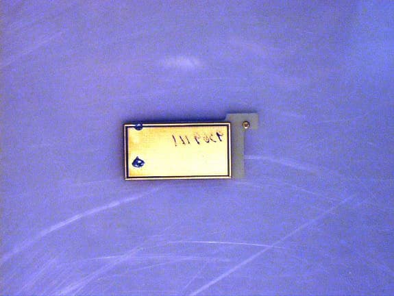
CSQHG200C
Jan 26, 2003BI HomeGuary 200
Equipment Class
DSC - Part 15 Security/Remote Control Transmitter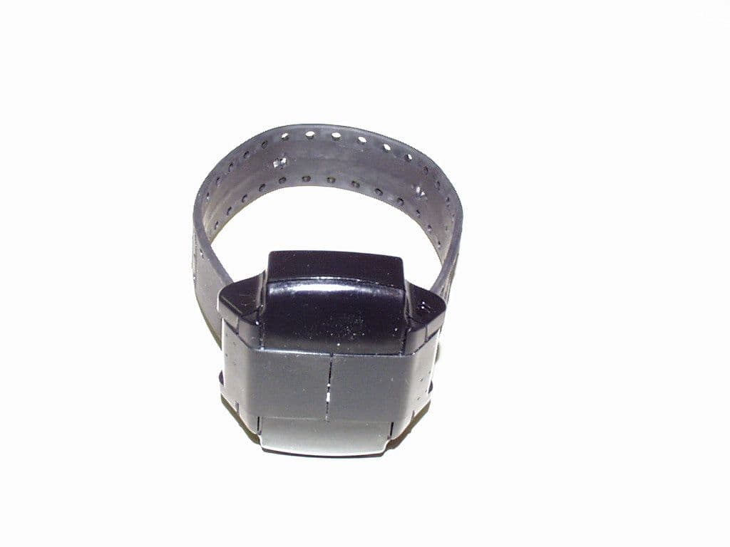
CSQHG200W
May 08, 2000Wrist-Mount Low Power RF Transmitter
Equipment Class
DXX - Part 15 Low Power Communication Device TransmitterCSQBI9010
Feb 28, 1995House Arrest Transmitter
Equipment Class
DSC - Part 15 Security/Remote Control Transmitter