CVT0517Radio Controlled Toy(Transmitter)
Nikko Co Ltd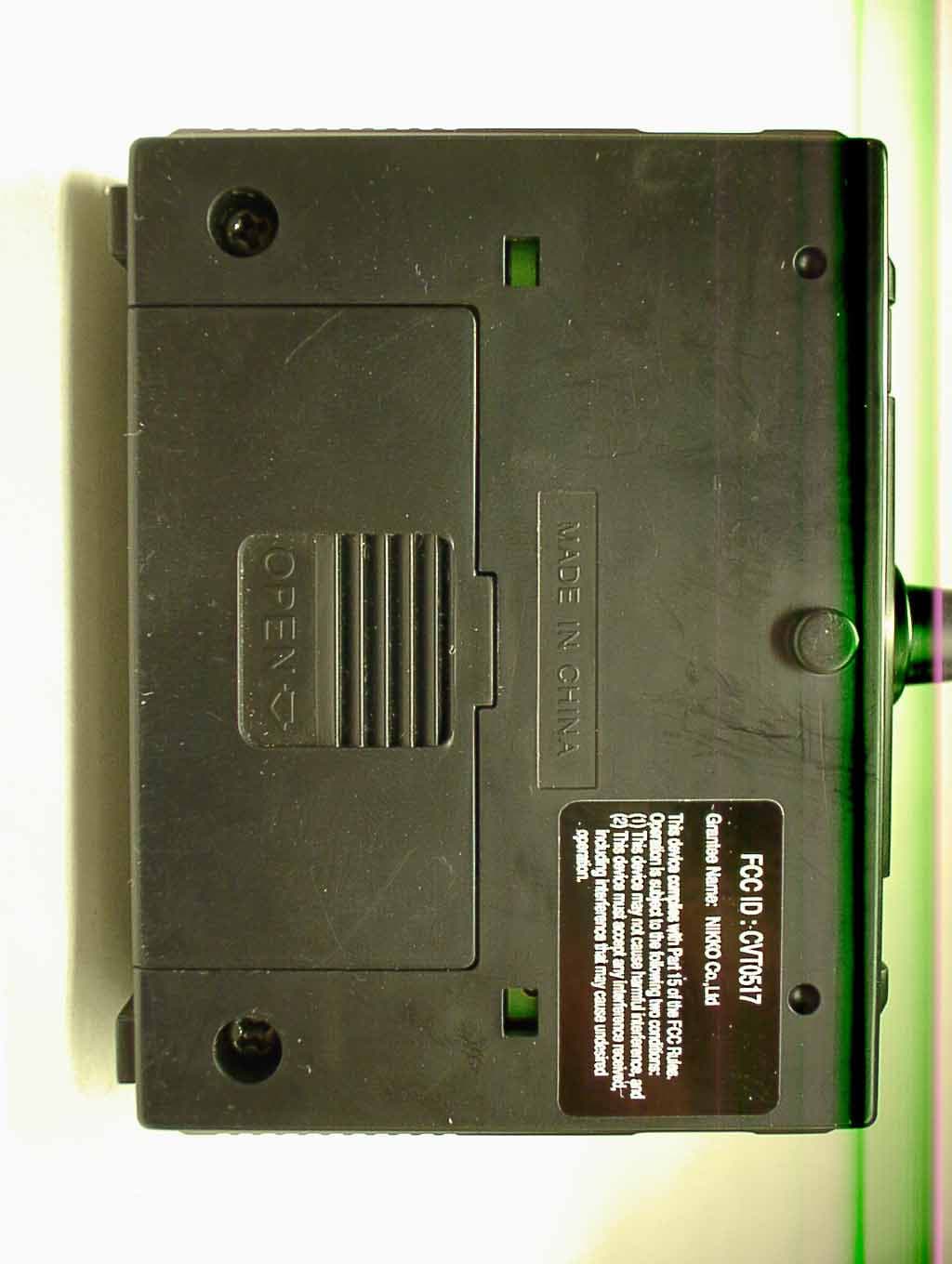
Click to zoom
Application Details
- Equipment Class
- DXX - Part 15 Low Power Communication Device Transmitter
- Date of Grant
- Feb 13, 2006
- Application Purpose
- Original Equipment
- Date of Application
- Feb 13, 2006
- Equipment Note
- Radio Controlled Toy(Transmitter)
- Frequency Range
- 26.99500000 - 27.25500000
- Company
- Nikko Co Ltd
- Country
- Japan
Documents & Files
Document Text
Text extracted from the exhibit documents filed with the FCC. Open a document above to read the original.
Users Manual
ON OFF 1/32scale Radio Control Car English / Español NIKKO c 60-4453 For ages 6 and up Repair and Parts Department Monday to Friday 8:30AM-5:30PM Central Time Repair:(800)736-4556 Parts:(800)776-4556 Fax:(972)578-7059 e-mail:[email protected] ATTENTION PARENTS It is recommended that this toy and all accessories be periodically examined for potential hazards and that any po - tentially hazardous parts be repaired or replaced. PRINTED IN CHINA Owner’s Manual l Please read carefully before starting to operate. Warning! use under the direct supervision of an adult. Actual product may vary from illustration of this manual. l l l Keep the display box and the manual for future reference. How to take the transmitter Phillips screwdriver (not included in the kit) Remove an antenna fitted on the back of the transmitter cover. *While holding the transmitter body, remove the screws that hold the transmitter cover. Then hold the projections at both sides of the transmitter cover and remove it. Transmitter cover Remove the transmitter by holding up from bot - tom as is illustrated. ※ When storing for a long time: Take the transmitter antenna off the transmitter after playing. Store it as the same condition as you purchased. You do not have to fix it by screws. Fix the body by screws only when you store it for a long period of time. How to install transmitter antenna Place the transmitter antenna into the antenna holder and screw it in clockwise. Do not install the antenna extended. If the antenna is not screwed in securely, the vehicle may not move at your control. Screw the antenna securely. Check the batteries regularly for leakage. Remove empty batteries from the toy. Never try to charge non-rechargeable batteries. Never short-circuit the terminals. BATTERY INSTALLATION Install battery making sure that + and - poles of the battery are positioned properly. Make sure vehicle’s on-off switch is turned OFF when installing battery. Remove all the batteries from the vehicle and the transmitter after playing. l l l l l l CAUTION WHEN USING BATTERIES Avoid combined use of new dry battries and old ones. Avoid combined use of Ni-Cd batteries and dry batteries. Avoid combined use of charged Ni-Cd batteries and discharged Ni-Cd batterries. 3 MAJOR CAUSES OF VEHICLE MALFUNCTION *WEAK BATTERIES *INCORRECT BATTERY INSTALLATION *INTERFERENCE Check to see that the battery is INSTALLED in the CORRECT position. To remove the battery lid, press the point marked “OPEN” and pull downward. Install the 9V battery, matching the po - larity(+ and -) symbols marked inside. One 006P(9V)battery Battery lid Battery lid ON/OFF switch ON <--> OFF Steering alignment lever 2AA alkaline(1.5V) or Ni-Cd(1.2V)batteries. Open the battery lid. Push the battery lid stopper with your finger as shown, and pull up the lid. The lid can be opened easily by using the tab next to the stopper. Install either two AA (1.5V) alkaline batteries or two Ni-Cd bat - teries. Install as indicated inside the battery compartment. Replace the battery lid. Make sure that the batteries are positioned in the right direction. tab Transmitter Vehicle l l l l OPERATING SAFETY RULES Select a SAFE place to operate your vehicle. Do not drive in the street. Avoid driving on SAND or through puddles of WATER. These hazards can impair performance. Check the surface ahead of you and watch for obstacles. The radio receiver in your vehicle and transmitter are sensitive instruments. Do not leave Vehicle or Transmitter near sources of HEAT or under DIRECT SUNLIGHT for long periods of time. Avoid leaving Vehicle or Transmitter OUTSIDE OVERNIGHT. NIGHT DAMPNESS IS HARMFUL to INTERIOR MECHANISM. DO NOT try to take apart or remodel any of the parts. RADIO INTERFERENCE: Sometimes erratic behavior or loss of control of vehicle is the result of interference caused by high tension wires, high voltage transformers certain types of building, concrete walls or narrow places where RADIO SIGNALS sent from your transmitter MAY BE SCATTERED thus making it DIFFICULT for your vehicle to receive a GOOD RADIO SIGNAL. If you encounter this type of behavior or loss of control, CHANGE TO A DIFFERENT LOCATION. You will encounter INTERFERENCE if ANOTHER radio controlled vehicle or CB radio is operating in the vicinity on your SAME FREQUENCY. CHANGES OR MODIFICATIONS NOT EXPRESSLY APPROVED BY THE MANUFACTURER FOR COMPLI - ANCE COULD VOID THE USER’S AUTHORITY TO OPERATE THE EQUIPMENT. (To prevent unnecessary power loss) The transmitter power is automatically turned ON when the speed control push button is operated either to the forward running or reverse running positions. When the button is returned to the neutral position, the trans - mitter power is turned OFF. When the transmitter power is turned OFF, the vehicle can be jammed by other transceiver radio waves and start to move abnormally. HOW TO PLAY 1. Turn ON the vehicle. 2. Operate the vehicle with transmitter. 3. Turn OFF the vehicle after operating. 4. Remove all the batteries both from the vehicle and the transmitter. * Please follow the above sequence of operation. ON/OFF switch When the vehicle slows down or starts moving erratically, replace all the vehicle's batteries with fresh ones. You can control the vehicle at a longer distance by holding the transmitter higher with the antenna straight up. l l TO ADJUST STEERING ALIGNMENT Adjust the steering alignment lever on the underside of the vehicle when the vehicle does not run straight. Steering alignment lever 60-4454 Keep out of reach of small children under 36 months old as there is danger of getting hurt. DO NOT operate your vehicle on thick-piled carpets. It can be dangerous since the carpet fiber may twine around a shaft and cause a motor overheated. Caution This toy vehicle needs periodic maintenance and cleaning. Cleaning and maintenance: THE FCC WANTS YOU KNOW This device complies with part 15 of the FCC Rules, Operation is subject to the following two conditions: (1)This devic…
Text truncated - open the document above for the full version.
Operational Description
NO.0517TX CIRCUIT EXPLANATION FCC ID :CVT0517 1) The power circuit status to operate when SW1 or SW2 are turn ON. 2) Q1 forms the Radio Frequency oscillator. 3) The Amplitude Modulation of the Radio Frequency is performed in Q2 by placing the waves on Audio Frequency. 4) AM. waves are output into the collector of Q2,passed through the filter, and is transmitted from the Antenna. NIKKO CO.,LTD R&D Dept. M.MIYAURA
Test Report
JAPAN QUALITY ASSURANCE ORGANIZATION 21-25, KINUTA 1-CHOME, SETAGAYA-KU, TOKYO 157-8573 JAPAN PHONE +81-3-3416-0111, FAX +81-3-3416-9691 JQA File No. : 400-50749 Issue Date : February 7, 2006 Page 1 of 34 EMI TEST REPORT JQA File No. : 400-50749 Model No. : 0517 Type of Equipment : Radio Controlled Toy (Transmitter) Regulations Applied : CFR 47 FCC Rules and Regulations Part 15 FCC ID : CVT0517 Applicant : NIKKO CO., LTD. Address : 1-7-14, Mizumoto, Katsushika-ku, Tokyo 125-0032, Japan Manufacturer : ZINTECH TOYS MANUFACTURING LTD. Address : The Sixth Economical Develop District, Li Uk, Wusha, Changan, Dongguan, Guangdong Received date of EUT : February 1, 2006 Final Judgment : Passed Test results in this report are obtained in use of equipment that is traceable to National Institute of Advanced Industrial Science and Technology (AIST) of Japan and National Institute of Information and Communications Technology(NICT) of Japan. The test results only respond to the tested sample. This report should not be reproduced except in full, without the written approval of JQA EMC Engineering Dept. Testing Div. JQA File No. :400-50749 FCC ID :CVT0517 Model No. :0517 Issue Date :February 7, 2006 Standard :CFR 47 FCC Rules Part 15 Page 2 of 34 JAPAN QUALITY ASSURANCE ORGANIZATION TABLE OF CONTENTS Page 1 Documentation 1.1 Test Regulation 3 1.2 General Information 3 1.3 Test Condition 4 – 8 1.4 EUT Modifications / Deviation from Standard 9 1.5 Test results 10 1.6 Summary 11 1.7 Test Configuration / Operation of EUT 12 1.8 EUT Arrangement(Drawing) 13 1.9 Preliminary Test and Test-setup (Drawings) 14 – 19 1.10 EUT Arrangement (Photographs) 20 – 21 2 Test Data 2.1 AC Power Line Conducted Emission N/A 2.2 Radiated Emission (Electric Field) 22 – 23 2.3 Frequency Stability N/A 2.4 Occupied Bandwidth 24 – 30 3 Appendix Test instruments List 31 – 34 JQA File No. :400-50749 FCC ID :CVT0517 Model No. :0517 Issue Date :February 7, 2006 Standard :CFR 47 FCC Rules Part 15 Page 3 of 34 JAPAN QUALITY ASSURANCE ORGANIZATION 1 DOCUMENTATION 1.1 TEST REGULATION FCC Rules and Regulations Part 15 Subpart A and C Intentional Radiators Test procedure : AC power line conducted emission, radiated emission, frequency stability and occupied bandwidth tests were performed according to the procedures in ANSI C63.4-2003. 1.2 GENERAL INFORMATION 1.2.1 Test facility : 1) Test Facility located at EMC Engineering Dept. Testing Div. : - No.2 and 3 Anechoic Chambers( 3 meters Site ). - Shielded Enclosure. 2) EMC Engineering Dept. Testing Div. is recognized under the National Voluntary Laboratory accreditation Program for satisfactory compliance established in title 15, Part 285 Code of Federal Regulations. NVLAP Lab Code : 200189-0 1.2.2 Description of the Equipment Under Test (EUT) : 1) Type of Equipment : Radio Controlled Toy (Transmitter) 2) Product Type : Production 3) Category : Low Power Communication Device Transmitter 4) EUT Authorization : Certification 5) FCC ID : CVT0517 6) Trade Name : NIKKO 7) Model No. : 0517 8) Operating Frequency Range : 27.145 MHz 9) Highest Frequency Used in the EUT : 27.145 MHz 10) Serial No. : None 11) Date of Manufacture : None 12) Power Rating : DC 9.0V(Battery) 13) EUT Grounding : None 1.2.3 Definitions for symbols used in this test report : x - indicates that the listed condition, standard or equipment is applicable for this report. - indicates that the listed condition, standard or equipment is not applicable for this report. JQA File No. :400-50749 FCC ID :CVT0517 Model No. :0517 Issue Date :February 7, 2006 Standard :CFR 47 FCC Rules Part 15 Page 4 of 34 JAPAN QUALITY ASSURANCE ORGANIZATION 1.3 TEST CONDITION 1.3.1 The measurement of the AC Power Line Conducted Emission - was performed in the following test site. x - was not applicable. Test location : Safety & EMC Center EMC Engineering Dept. Testing Div. 21-25, Kinuta 1-chome, Setagaya-ku, Tokyo 157-8573, Japan - Shielded Enclosure - Anechoic Chamber No. 2 (portable Type) Used test instruments : Type Number of test instruments (Refer to Appendix) Test Receiver N/A Spectrum Analyzer N/A Cable N/A AMN(for EUT) N/A AMN(for Peripheral) N/A Termination N/A JQA File No. :400-50749 FCC ID :CVT0517 Model No. :0517 Issue Date :February 7, 2006 Standard :CFR 47 FCC Rules Part 15 Page 5 of 34 JAPAN QUALITY ASSURANCE ORGANIZATION 1.3.2 The measurement of the Radiated Emission(9 kHz – 30 MHz) x - was performed in the following test site. - was not applicable. Test location : Safety & EMC Center EMC Engineering Dept. Testing Div. 21-25, Kinuta 1-chome, Setagaya-ku, Tokyo 157-8573, Japan x - Anechoic Chamber No. 2 (3 meters) - Anechoic Chamber No. 3 (3 meters) Validation of Site Attenuation : 1) Last Confirmed Date : N/A 2) Interval : N/A Used test instruments : Type Number of test instruments (Refer to Appendix) Test Receiver 8 Antenna 21 Cable 43 JQA File No. :400-50749 FCC ID :CVT0517 Model No. :0517 Issue Date :February 7, 2006 Standard :CFR 47 FCC Rules Part 15 Page 6 of 34 JAPAN QUALITY ASSURANCE ORGANIZATION 1.3.3 The measurement of the Radiated Emission(30 MHz – 1000 MHz) x - was performed in the following test site. - was not applicable. Test location : Safety & EMC Center EMC Engineering Dept. Testing Div. 21-25, Kinuta 1-chome, Setagaya-ku, Tokyo 157-8573, Japan x - Anechoic Chamber No. 2 (3 meters) - Anechoic Chamber No. 3 (3 meters) Validation of Site Attenuation : 1) Last Confirmed Date :March, 2005 2) Interval :1 year Used test instruments : Type Number of test instruments (Refer to Appendix) Test Receiver 11 Antenna 26, 28 Cable 38 RF Amplifier N/A JQA File No. :400-50749 FCC ID :CVT0517 Model No. :0517 Issue Date :February 7, 2006 Standard :CFR 47 FCC Rules Part 15 Page 7 of 34 JAPAN QUALITY ASSURANCE ORGANIZATION 1.3.4 The measurement of the Radiated Emission(Above 1000 MHz) - was performed in the following test site. x - was not applicable. Test location : Safety & EMC Center EMC Engineering Dept. Testing Div. 21-25, Kinuta 1-chome, Seta…
Text truncated - open the document above for the full version.
Test Setup Photos
JQA File No. :400-50749 FCC ID :CVT0517 Model No. :0517 Issue Date :February 7, 2006 Standard :CFR 47 FCC Rules Part 15 Page 20 of 34 JAPAN QUALITY ASSURANCE ORGANIZATION 1.10 TEST ARRANGEMENT (PHOTOGRAPHS) PHOTOGRAPHS OF EUT CONFIGURATION FOR RADIATED EMISSIONS MEASUREMENT Photograph present configuration with maximum emission JQA File No. :400-50749 FCC ID :CVT0517 Model No. :0517 Issue Date :February 7, 2006 Standard :CFR 47 FCC Rules Part 15 Page 21 of 34 JAPAN QUALITY ASSURANCE ORGANIZATION PHOTOGRAPHS OF EUT CONFIGURATION FOR RADIATED EMISSIONS MEASUREMENT Photograph present configuration with maximum emission
Contact Information
Applicant
Minori Oohira
81-3 3609-0900Fax: 81 3-3609-1033
Test Firm
Japan Qlty. Assur. Org. Safety & EMC CtrHideki Kajiwara
Technical Specifications
| # | Rule Parts | Frequency Range | Power Output |
|---|---|---|---|
| 1 | 15C | 26.995 MHz - 27.255 MHz | - |
Other Applications from Nikko Co Ltd
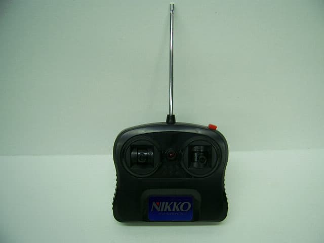
CVTTA7752
Mar 12, 2008Radio Controlled Toy
Equipment Class
DXX - Part 15 Low Power Communication Device Transmitter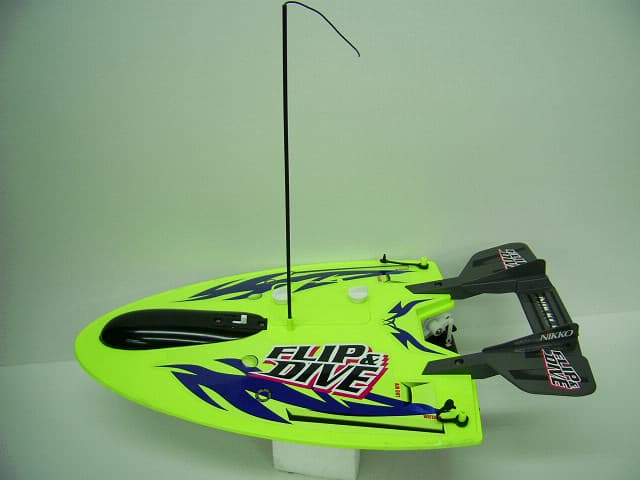
CVTRA4040H
Mar 12, 2008Radio Controlled Toy
Equipment Class
CYY - Communications Receiver used w/Pt 15 Transmitter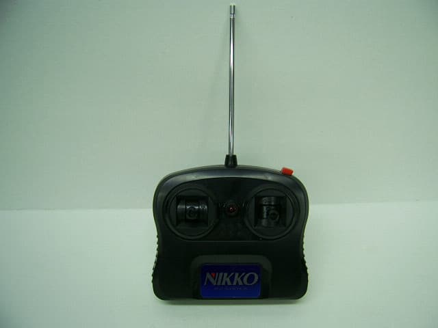
CVTTP7752H
Mar 12, 2008Radio Controlled Toy
Equipment Class
DXX - Part 15 Low Power Communication Device Transmitter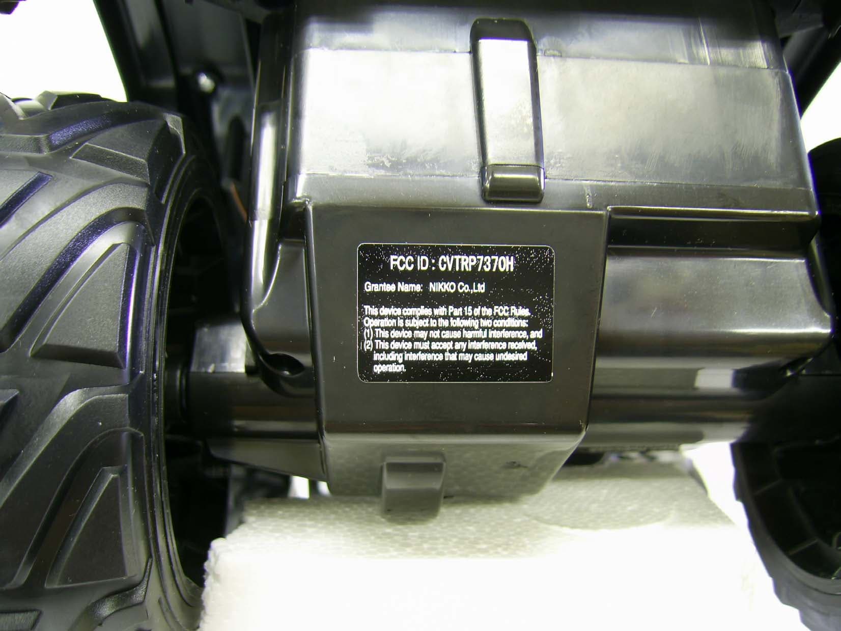
CVTRP7370H
Jul 24, 2007Radio Controlled Toy Receiver
Equipment Class
CYY - Communications Receiver used w/Pt 15 Transmitter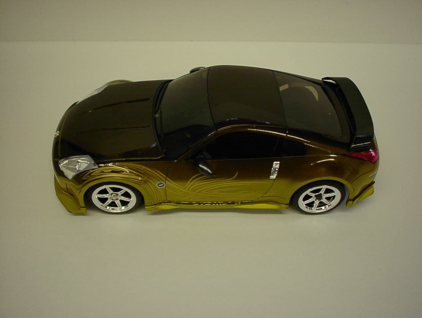
CVTRP7340H
Jan 28, 2007Radio Controlled Toy
Equipment Class
CRR - Superregenerative Receiver