CVT12701TX-27ASTON MARTIN DBS
Nikko Co Ltd
Click to zoom
Application Details
- Equipment Class
- DXX - Part 15 Low Power Communication Device Transmitter
- Date of Grant
- Aug 30, 2006
- Application Purpose
- Original Equipment
- Date of Application
- Aug 30, 2006
- Equipment Note
- ASTON MARTIN DBS
- Frequency Range
- 27.14500000 - 27.14500000
- Company
- Nikko Co Ltd
- Country
- Japan
Documents & Files
Document Text
Text extracted from the exhibit documents filed with the FCC. Open a document above to read the original.
Users Manual
Please read this user’s guide before installing, setting up and using your new car www.radioshack.com 60-4458 James Bond Aston Martin DBS 1:12 Scale RC Car James Bond Aston Martin DBS Transmitter Transmitter Antenna User’s guide Vehicle Antenna Tube what’s included In your transmitter Your transmitter requires one 9V alkaline battery (not supplied). Replace the battery when your transmitter’s control range decreases. 1. Open the battery cover and insert the battery as marked (+ and -). 2. Replace the cover. In your vehicle Your vehicle requires one 9.6V rechargeable battery pack (not supplied). 1. Set ON/OFF on the vehicle under the body on the driver’s side to OFF. 2. Use a coin to turn the battery compartment latch to OPEN. 3. Slide the battery compartment cover in the direction of the arrow and lift to open it. 4. Attach the vehicle’s connector to battery pack. Do not force them; they fit together only one way. 5. Place the battery pack in the battery compartment. The battery pack’s connector must be on the same side as the car’s matching connector. 6. Close the lid and snap it shut. installing your batteries • Do not use your vehicle near devices with transmitters using the same frequency (27 or 49 MHz). • If someone uses a CB nearby, it might interfere with the control of your vehicle. If this happens, move the vehicle away from the CB. • Never play with the vehicle in the street. • Be careful when you use the vehicle to avoid high-impact collisions with people and objects. • If your vehicle does not respond, drives slowly, or the range reduces, recharge the batteries in the vehicle. safety information Note: Actual product may vary from the images found in this document. Thank you for purchasing your James Bond Aston Martin DBS 1:12 Scale RC Car from RadioShack. Your vehicle comes in two frequencies (27MHz and 49MHz), so you and your friends can drive your car. 60-4458_UG_en.indd 108/22/2006 16:48:24 ©2006. RadioShack Corporation. All rights reserved. RadioShack and RadioShack.com are trademarks used by RadioShack Corporation. 60-4458 07A06 printed in China This product is warranted by RadioShack against manufacturing defects in material and workmanship under normal use for ninety (90) days from the date of purchase from RadioShack company- owned stores and authorized RadioShack franchisees and dealers. For complete warranty details and exclusions, check with your local RadioShack store. RadioShack Customer Relations 300 RadioShack Circle, Fort Worth, TX 76102 04/04 limited 90-day warranty This equipment has been tested and found to comply with the limits for a Class B digital device, pursuant to Part 15 of the FCC Rules. These limits are designed to provide reasonable protection against harmful interference in a residential installation. This equipment generates, uses, and can radi- ate radio frequency energy and, if not installed and used in accordance with the instructions, may cause harmful interference to radio communications. However, there is no guarantee that interference will not occur in a particu- lar installation. If this equipment does cause harmful interference to radio or television reception, which can be determined by turning the equipment off and on, the user is encouraged to try to correct the interference by one or more of the following measures: • Reorient or relocate the receiving antenna. • Increase the separation between the equipment and receiver. • Connect the equipment into an outlet on a circuit different from that to which the receiver is connected. • Consult your local RadioShack store or an experienced radio/TV technician for help. If you cannot eliminate the interference, the FCC requires that you stop using your Vehicle. Changes or modifications not expressly approved by RadioShack may cause interference and void the user’s authority to oper- ate the equipment. This device complies with Part 15 of the FCC Rules. Operation is subject to the following two conditions: (1) This device may not cause harmful interference, and (2) This device must accept any interference received, including interference that may cause undesired operation. Field Strength.........................................27.145MHz: 67.9 dBμV/m at 3m .................................................................49.86MHz: 65.6 dBμV/m at 3m Only use the antenna supplied with this product. This radiocommunication device complies with all the requirements of Industry Canada Standard RSS-310. This Class B digital apparatus complies with Canadian ICES-003. RF emission informations 1. Slide ON/OFF on the vehicle to ON. 2. Use the transmitter’s controls to steer your vehicle in the directions shown below. 3. Slide ON/OFF on the vehicle to OFF when you finish driving. Wheel alignment If the vehicle does not drive in a straight line when you release the right stick, adjust WHEEL ALIGNMENT (located between the front wheels, underneath the vehicle). Push to L if the vehicle is pulling to the right or to R if the vehicle is pulling to the left. driving your vehicle • Dispose of old batteries promptly and properly. Do not burn or bury batteries. • Use only fresh batteries of the required size and recommended type. • Do not leave dead or weak batteries in your transmitter or vehicle. If you do not plan to use your RC vehicle for a few weeks, remove the batteries from your transmitter and vehicle. Batteries can leak chemicals that may damage electronic parts. • Do not charge or recharge your battery pack when it is in the vehicle. • Do not overcharge your battery pack. • Do not recharge your battery pack immediately after use. Allow it to cool first. • Make sure your battery pack is securely fastened to your vehicle before playing. battery notes • Handle your vehicle and transmitter carefully. Do not drop them. • Used and store them only in normal temperature environments. • Keep the vehicle and transmitter away from dust and dirt, and wipe them with a damp cloth occasionally to keep them looking ne…
Text truncated - open the document above for the full version.
Operational Description
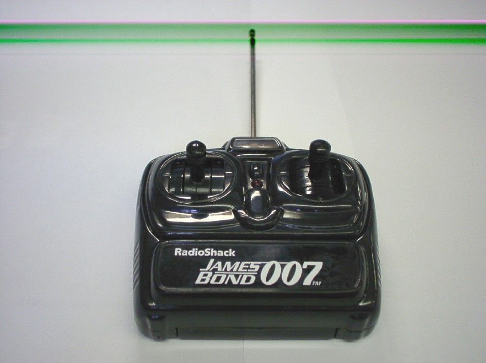
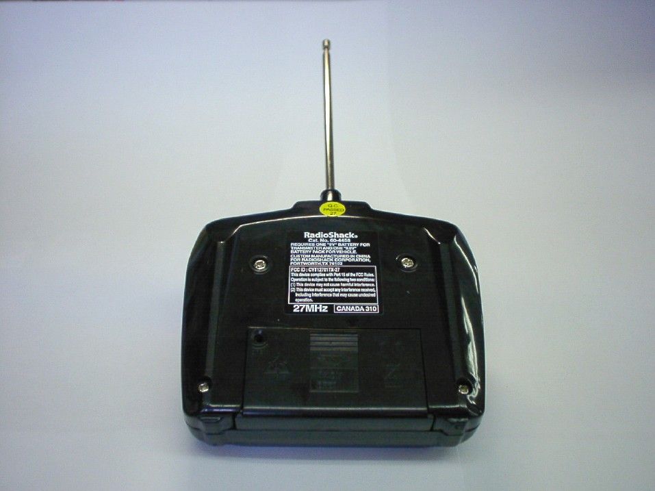
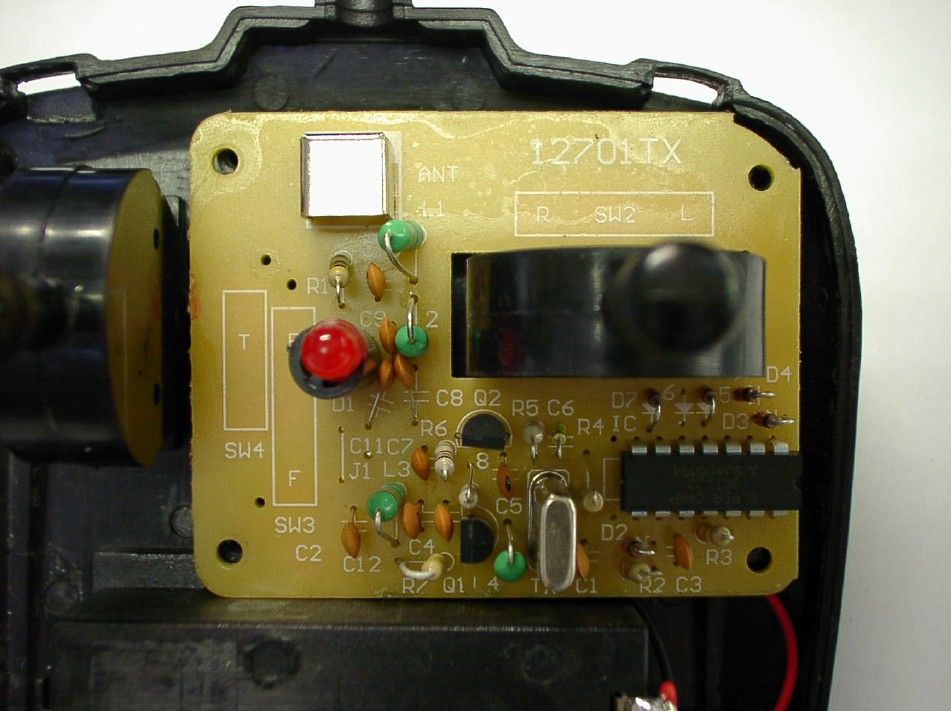
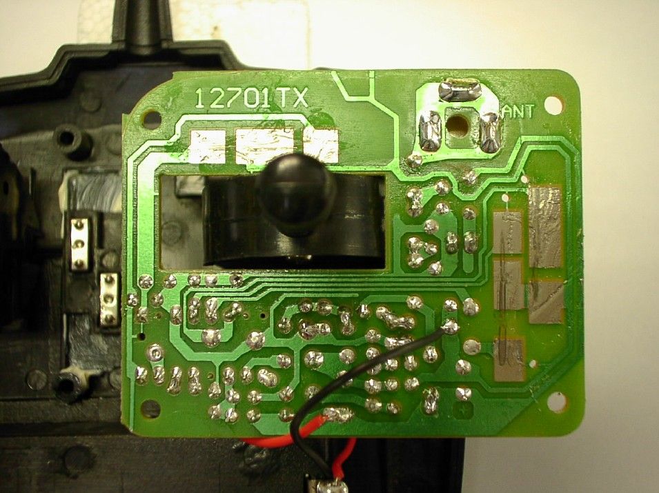
Operation Description for Aston Martin DBS The Radio control car for Aston Martin DBS is operates at 27.145MHz. The radio frequency is generated by crystal. The EUT is powered by 1 x 9V size battery and it has two control sticks in the EUT. When the forward, backward, turn left and turn right control stick is pushed once, it will transmit different radio control signal to receiver. Refer to the schematic, the major operation for the electronic components as below: - IC Tx2 and associated circuit act as encoder. - Q1, Crystal 27.145MHz and associated circuit act as oscillator. - Q2 and associated circuit act as RF amplify.
Schematics
604458 ELEC JULY-6 1 2 3 4 A BC D 4 3 2 1 D CB A Title Number Revision Size A4 Date: 4-Jul-2006 Sheet of File: E:\yanghao\BlockSchPcb.ddb Drawn By: ANT 9 V 006P Q1 2SC945 ˧˫ ˅ˊˁ˄ˇˈ ˠ ̨̍ D2 4.3V L42.2 uH R1 470 R2 330 R3 330K R7220K R8 100 R4 5.6K R5 33K R6 100 Q2 2SC945 C3 473Z C1 473Z C7103Z C482P C540P C682P C8 101P L32.2 uH L2 1.0 uH L1 6.8 uH C9 101P C10 56P ˦ ˪˅ 1 2 3 4 5 6 78 9 10 11 12 13 14 TX-2 D1 LED R L ˦ ˪ˆ B ˦ ˪ˇ T Transmitter Diagrams 604458TX 27MHz D41N4148 D31N4148 D5 1N4148 D7 1N4148 C2 473Z C11 473Z C12 473Z IC ˣ˔ ̊ ̆ˍʳ˄ʳˢ ̇ʳ˅
Test Report
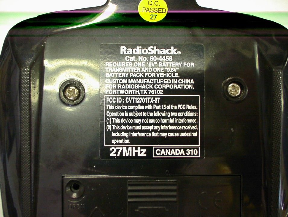
TEST REPORT Report No. : AG021378-001 Date : 2006 August 29 Page 1 of 11 FCC ID: CVT12701TX-27 This document shall not be reproduced except in full or with written approval by the laboratory. CMA Industrial Development Foundation Limited Room 1302, Yan Hing Centre, 9-13 Wong Chuk Yeung St.., Fo Tan, Shatin, Hong Kong. Tel: (852) 2698 8198 Fax: (852) 2695 4177 E-mail: [email protected] Web Site: http://www.cmatcl.com Application No. : LG219095(4) Applicant : Nikko (NICS Engineering Ltd.) Unit 2701 & 2710-19, 27/F., The Metropolis Tower, The Metropolis Drive, Hunghom, Kowloon, Hong Kong Sample Description : One(1) submitted sample(s) stated to be Aston Martin DBS of Model No. 60-4458 Radio Frequency : 27.145MHz Transmitter Rating : 1 x 9V size battery No. of submitted sample : One(1) piece(s) *** Date Received : 2006 August 10 Test Period : 2006 August 14 – 2006 August 21 Test Requested : FCC Part 15 Certification. Test Method : 47 CFR Part 15 (10-1-05 Edition) ANSI C63.4 – 2003 Test Result : See attached sheet(s) from page 2 to 11. Conclusion : The submitted sample was found to comply with requirement of FCC Part 15 Subpart C. For and on behalf of CMA Industrial Development Foundation Limited Authorized Signature : ____________________________________________________ Danny Chui Deputy Manager - EL. Division TEST REPORT Report No. : AG021378-001 Date : 2006 August 29 Page 2 of 11 FCC ID: CVT12701TX-27 This document shall not be reproduced except in full or with written approval by the laboratory. CMA Industrial Development Foundation Limited Room 1302, Yan Hing Centre, 9-13 Wong Chuk Yeung St.., Fo Tan, Shatin, Hong Kong. Tel: (852) 2698 8198 Fax: (852) 2695 4177 E-mail: [email protected] Web Site: http://www.cmatcl.com Table of Contents 1 General Information............................................................................................................................. 3 1.1 General Description ..................................................................................................................... 3 1.2 Location of the test site ................................................................................................................ 4 1.3 List of measuring equipment........................................................................................................ 5 2 Description of the radiated emission test ............................................................................................. 6 2.1 Test Procedure ............................................................................................................................. 6 2.2 Test Result ................................................................................................................................... 6 2.3 Radiated Emission Measurement Data ........................................................................................ 7 3 Description of the Line-conducted Test............................................................................................... 8 3.1 Test Procedure ............................................................................................................................. 8 3.2 Test Result ................................................................................................................................... 8 3.3 Graph and Table of Conducted Emission Measurement Data ..................................................... 8 4 Photograph ........................................................................................................................................... 9 4.1 Photographs of the Test Setup for Radiated Emission and Conduction Emission....................... 9 4.2 Photographs of the External and Internal Configurations of the EUT......................................... 9 5 Supplementary document................................................................................................................... 10 5.1 Bandwidth .................................................................................................................................. 10 5.2 Duty cycle .................................................................................................................................. 10 5.3 Transmission time ...................................................................................................................... 10 6 Appendices......................................................................................................................................... 11 TEST REPORT Report No. : AG021378-001 Date : 2006 August 29 Page 3 of 11 FCC ID: CVT12701TX-27 This document shall not be reproduced except in full or with written approval by the laboratory. CMA Industrial Development Foundation Limited Room 1302, Yan Hing Centre, 9-13 Wong Chuk Yeung St.., Fo Tan, Shatin, Hong Kong. Tel: (852) 2698 8198 Fax: (852) 2695 4177 E-mail: [email protected] Web Site: http://www.cmatcl.com 1 General Information 1.1 General Description The equipment under test (EUT) is a transmitter for Aston Martin DBS. It operates at 27.145MHz which is controlled by a crystal. The EUT is powered by 1 x 9V size battery and it has two control sticks in the EUT. When the forward, backward, turn left and turn right control stick is pushed once, it will transmit different radio control signal to receiver. The brief circuit description is listed as follows: - IC Tx2 and associated circuit act as encoder. - Q1, Crystal 27.145MHz and associated circuit act as oscillator. - Q2 and associated circuit act as RF amplify. TEST REPORT Report No. : AG021378-001 Date : 2006 August 29 Page 4 of 11 FCC ID: CVT12701TX-27 This document shall not be reproduced except in full or with written approval by the laboratory. CMA Industrial Development Foundation Limited Room 1302, Yan Hing Centre, 9-13 Wong Chuk Yeung St.., Fo Tan, Shatin, Hong Kong. Tel: (852) 2698 8198 Fax: (852) 2695 4177 E-mail: [email protected] Web Site: http…
Text truncated - open the document above for the full version.
Test Report
Bandwidth Plot Bandwidth 1
Test Report
Duty Cycle Duty Cycle 1 Duty Cycle 2 . Duty Cycle 3
Contact Information
Applicant
Minori Oohira
81-3 3609-0900Fax: 81 3-3609-1033
Test Firm
CMA Industrial Development Foundations LimitedStephen Lam
Technical Specifications
| # | Rule Parts | Frequency Range | Power Output |
|---|---|---|---|
| 1 | 15C | 27.145 MHz - 27.145 MHz | - |
Other Applications from Nikko Co Ltd
CVTTA7752
Mar 12, 2008Radio Controlled Toy
Equipment Class
DXX - Part 15 Low Power Communication Device Transmitter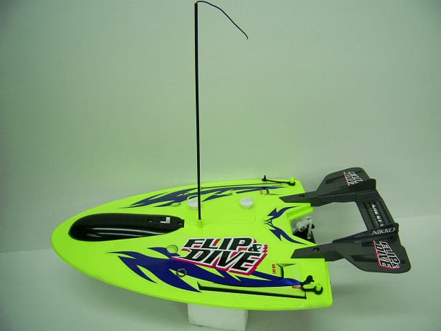
CVTRA4040H
Mar 12, 2008Radio Controlled Toy
Equipment Class
CYY - Communications Receiver used w/Pt 15 Transmitter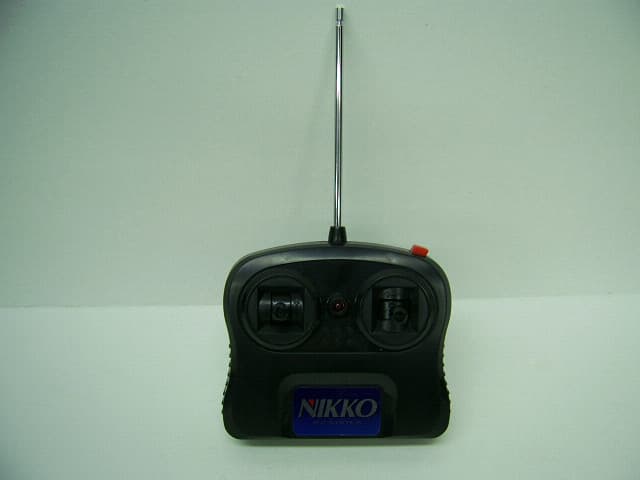
CVTTP7752H
Mar 12, 2008Radio Controlled Toy
Equipment Class
DXX - Part 15 Low Power Communication Device Transmitter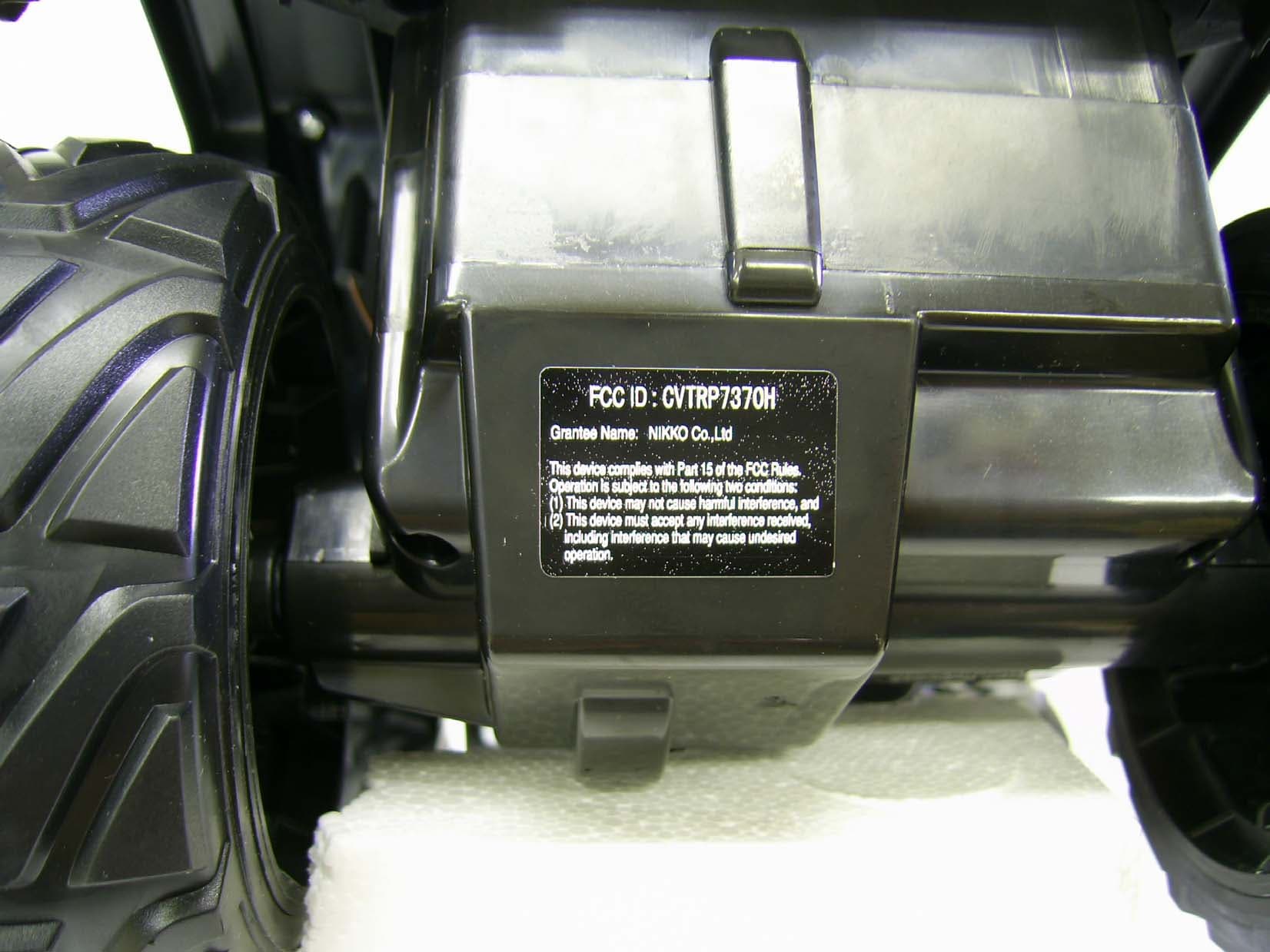
CVTRP7370H
Jul 24, 2007Radio Controlled Toy Receiver
Equipment Class
CYY - Communications Receiver used w/Pt 15 Transmitter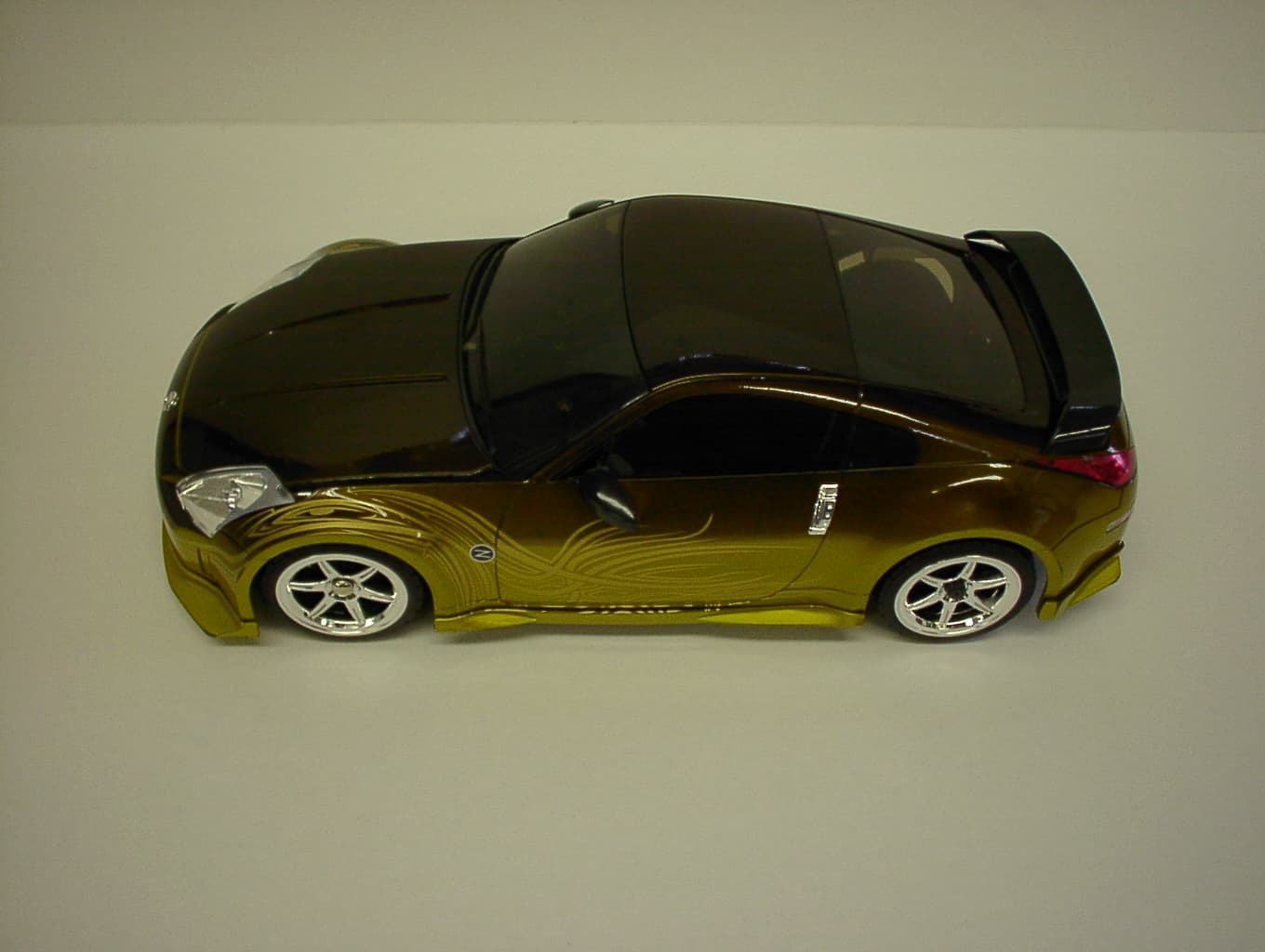
CVTRP7340H
Jan 28, 2007Radio Controlled Toy
Equipment Class
CRR - Superregenerative Receiver