CVTRP6401HRemote Control Toy Receiver
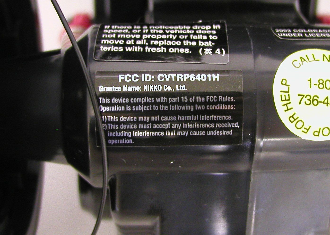
Nikko Co Ltd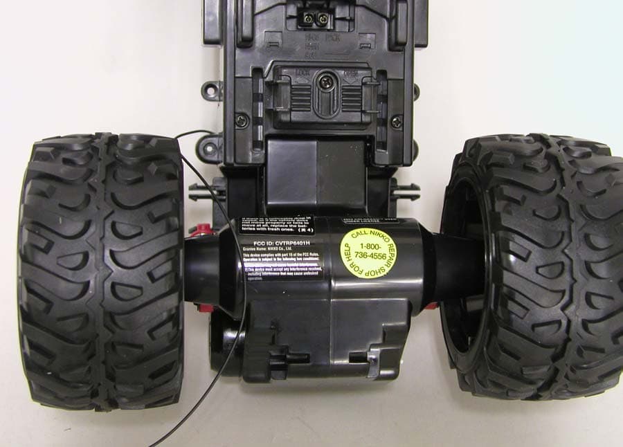
Click to zoom
Application Details
- Equipment Class
- CRR - Superregenerative Receiver
- Date of Grant
- Apr 30, 2003
- Application Purpose
- Original Equipment
- Date of Application
- Apr 30, 2003
- Equipment Note
- Remote Control Toy Receiver
- Frequency Range
- 49.83000000 - 49.89000000
- Company
- Nikko Co Ltd
- Country
- Japan
Documents & Files
Document Text
Text extracted from the exhibit documents filed with the FCC. Open a document above to read the original.
Operational Description
NO.RP6401 CIRCUIT EXPLANATION FCC ID:CVTRP6401H 1)The Radio Frequency inputted through The ANTENNA,is passed to the Super regenerative receiver,formed by TR1,where the Action Signal is detected. 2)The Action Signal is decode in the IC.,and are send to each output terminal. 3)TR6,7,8,9, IC2 and 3 form the power motor drive control circuit. TR10,11,12,13,14 and 15 form the steering control circuit. TR4 and 5 form the pulse control circuit. TR21 and 22 form the timer circuit. 4)Forward motion IC1’s 11p(pin) is turned Hi,and TR6 and 8 are turned ON,and IC2’s 7p and 8p are turned Low,and IC3’s 5p and 6p are turned Hi to make a Forward drive. 5)Backward motion IC1’s 10p is turned Hi,and TR7 and 9 are turned ON,and IC2’s 5p and 6p are turned Hi,and IC3’s 7p and 8p are turned ON by pulse drive circuit to make a backward drive. 6)Right turns IC.6P is turned Hi,and TR10,13 and14 are turned on to make a Right turn. 7)Left turns IC.7P is turned Hi,and TR11,12 and 15 are turned on to make a Left turn.
Test Report
JAPAN QUALITY ASSURANCE ORGANIZATION 21-25, KINUTA 1-CHOME, SETAGAYA-KU, TOKYO 157-8573 JAPAN PHONE (03) 3416-0111, FAX (03) 3416-9691 JQA APPLICATION NO.: 400-30092 Issue Date : April 28, 2003 Page 1 of 24 EMI TEST REPORT JQA APPLICATION NO. : 400-30092 Model No. : RP6401H Type of Equipment : Radio Controlled Toy (Superregenerative Type) Regulations Applied : CFR 47 FCC Rules and Regulations Part 15 FCC ID : CVTRP6401H Applicant : NIKKO CO., LTD. Address : 1-7-14, Mizumoto, Katsushika-ku, Tokyo 125-0032, Japan Manufacturer : NIKKO ELECTRONICS BHD. Address : Plot 497 Prai Free Trade Zone, Prai Industrial Estate, 13600 Prai, Penang, Malaysia Received date of EUT : April 25, 2003 Final Judgment : Passed Test results in this report are obtained in use of equipment that is traceable to National Institute of Advanced Industrial Science and Technology (AIST) of Japan and Communication Research Laboratory (CRL) of Japan. The test results only respond to the tested sample. This report should not be reproduced except in full, without the written approval of JQA EMC Engineering Dept. Testing Div. C O P Y JQA Application No. :400-30092 FCC ID : CVTRP6401H Model No. :RP6401H Issue Date :April 28, 2003 Standard :CFR 47 FCC Rules Part 15 Page 2 of 24 JAPAN QUALITY ASSURANCE ORGANIZATION TABLE OF CONTENTS Page 1 Documentation 1.1 Test Regulation 3 1.2 General Information 3 1.3 Test Condition 4 – 7 1.4 EUT Modifications / Deviation from Standard 8 1.5 Test results / Uncertainty 9 1.6 Summary 10 1.7 Test Configuration / Operation of EUT 11 1.8 EUT Arrangement (Drawings) 12 1.9 Preliminary Test and Test-setup (Drawings) 13 – 16 1.10 EUT Arrangement (Photographs) 17 2 Test Data 2.1 AC Power Line Conducted Emission N/A 2.2 Radiated Emission (Electric Field) 18 – 20 2.3 Antenna Conducted Power N/A 3 Appendix Test instruments List 21 – 24 C O P Y JQA Application No. :400-30092 FCC ID : CVTRP6401H Model No. :RP6401H Issue Date :April 28, 2003 Standard :CFR 47 FCC Rules Part 15 Page 3 of 24 JAPAN QUALITY ASSURANCE ORGANIZATION 1 DOCUMENTATION 1.1 TEST REGULATION FCC Rules and Regulations Part 15 Subpart A and B (June 23, 1989) Superregenerative Receiver Test procedure : AC power line conducted emission, radiated emission and antenna conducted power tests were performed according to the procedures in ANSI C63.4-1992. 1.2 GENERAL INFORMATION 1.2.1 Test facility : 1) Test Facility located at EMC Engineering Dept. Testing Div. : - No.2 and 3 Anechoic Chambers( 3 meters Site ). - Shielded Enclosure. Expiration date of FCC test facility filing : May 27, 2005 2) EMC Engineering Dept. Testing Div. is recognized under the National Voluntary Laboratory accreditation Program for satisfactory compliance established in title 15, Part 285 Code of Federal Regulations. NVLAP Lab Code : 200189-0 (Effective through : June 30, 2003) 1.2.2 Description of the Equipment Under Test (EUT) : 1) Type of Equipment : Radio Controlled Toy 2) Product Type : Production 3) Category : Superregenerative Receiver 4) EUT Authorization : Certification 5) FCC ID : CVTRP6401H 6) Trade Name : NIKKO 7) Model No. : RP6401H 8) Tuning Frequency Range : 49.830 MHz – 49.890 MHz 9) Highest Frequency Used in the EUT : - 10) Serial No. : None 11) Date of Manufacture : April 2003 12) Power Rating : 9.6 VDC(Ni-cd Battery) 13) EUT Grounding : None 1.2.3 Definitions for symbols used in this test report : x - indicates that the listed condition, standard or equipment is applicable for this report. - indicates that the listed condition, standard or equipment is not applicable for this report. C O P Y JQA Application No. :400-30092 FCC ID : CVTRP6401H Model No. :RP6401H Issue Date :April 28, 2003 Standard :CFR 47 FCC Rules Part 15 Page 4 of 24 JAPAN QUALITY ASSURANCE ORGANIZATION 1.3 TEST CONDITION 1.3.1 The measurement of the AC Power Line Conducted Emission - was performed in the following test site. x - was not applicable. Test location : Safety & EMC Center EMC Engineering Dept. Testing Div. 21-25, Kinuta 1-chome, Setagaya-ku, Tokyo 157-8573, Japan - Shielded Enclosure - Anechoic Chamber No. 2 (portable Type) Used test instruments : Type Number of test instruments (Refer to Appendix) Test Receiver Spectrum Analyzer Cable AMN(for EUT) AMN(for Peripheral) Termination C O P Y JQA Application No. :400-30092 FCC ID : CVTRP6401H Model No. :RP6401H Issue Date :April 28, 2003 Standard :CFR 47 FCC Rules Part 15 Page 5 of 24 JAPAN QUALITY ASSURANCE ORGANIZATION 1.3.2 The measurement of the Radiated Emission(30 MHz – 1000 MHz) x - was performed in the following test site. - was not applicable. Test location : Safety & EMC Center EMC Engineering Dept. Testing Div. 21-25, Kinuta 1-chome, Setagaya-ku, Tokyo 157-8573, Japan x - Anechoic Chamber No. 2 (3 meters) - Anechoic Chamber No. 3 (3 meters) Validation of Site Attenuation : 1) Last Confirmed Date :March, 2003 2) Interval :1 year Used test instruments : Type Number of test instruments (Refer to Appendix) Test Receiver TR05 Antenna AN06, AN08, AN07 Cable CA01 RF Amplifier N/A Signal Generator SG05 C O P Y JQA Application No. :400-30092 FCC ID : CVTRP6401H Model No. :RP6401H Issue Date :April 28, 2003 Standard :CFR 47 FCC Rules Part 15 Page 6 of 24 JAPAN QUALITY ASSURANCE ORGANIZATION 1.3.3 The measurement of the Radiated Emission(Above 1000 MHz) - was performed in the following test site. x - was not applicable. Test location : Safety & EMC Center EMC Engineering Dept. Testing Div. 21-25, Kinuta 1-chome, Setagaya-ku, Tokyo 157-8573, Japan - No. 2 site (3 meters) - No. 3 site (3 meters) Validation of Site Attenuation : 1) Last Confirmed Date :N/A 2) Interval :N/A Used test instruments : Type Number of test instruments (Refer to Appendix) Test Receiver Spectrum Analyzer Cable Antenna RF Amplifier C O P Y JQA Application No. :400-30092 FCC ID : CVTRP6401H Model No. :RP6401H Issue Date :April 28, 2003 Standard :CFR 47 FCC Rules Part 15 Page 7 of 24 JAPAN QUALITY ASSURANCE ORGANIZATION 1.3.4 The measurement of the Antenna Conduc…
Text truncated - open the document above for the full version.
Test Setup Photos
JQA Application No. :400-30092 FCC ID : CVTRP6401H Model No. :RP6401H Issue Date :April 28, 2003 Standard :CFR 47 FCC Rules Part 15 Page 17 of 24 JAPAN QUALITY ASSURANCE ORGANIZATION 1.10 TEST ARRANGEMENT (PHOTOGRAPHS) PHOTOGRAPHS OF EUT CONFIGURATION FOR RADIATED EMISSIONS MEASUREMENT Photograph present configuration with maximum emission C O P Y
Contact Information
Applicant
Minori Oohira
81-3 3609-0900Fax: 81 3-3609-1033
Test Firm
Japan Quality Assurance Org.Tetsuo Kato
Technical Specifications
| # | Rule Parts | Frequency Range | Power Output |
|---|---|---|---|
| 1 | 15B | 49.83 MHz - 49.89 MHz | - |
Other Applications from Nikko Co Ltd
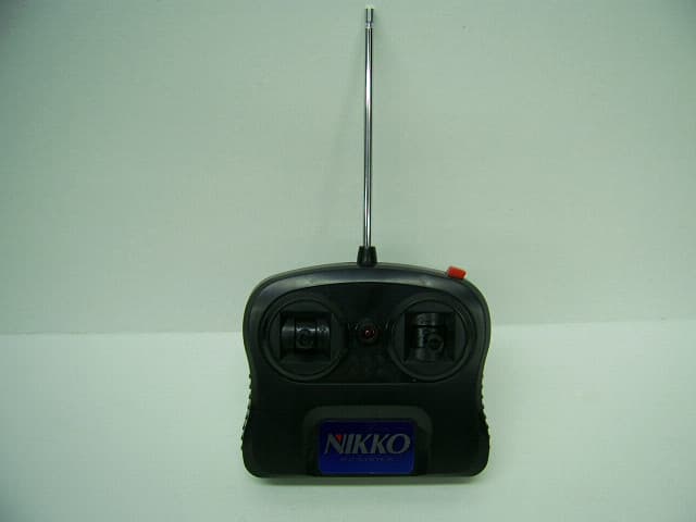
CVTTA7752
Mar 12, 2008Radio Controlled Toy
Equipment Class
DXX - Part 15 Low Power Communication Device Transmitter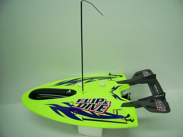
CVTRA4040H
Mar 12, 2008Radio Controlled Toy
Equipment Class
CYY - Communications Receiver used w/Pt 15 Transmitter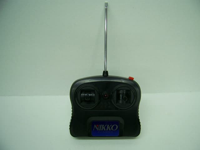
CVTTP7752H
Mar 12, 2008Radio Controlled Toy
Equipment Class
DXX - Part 15 Low Power Communication Device Transmitter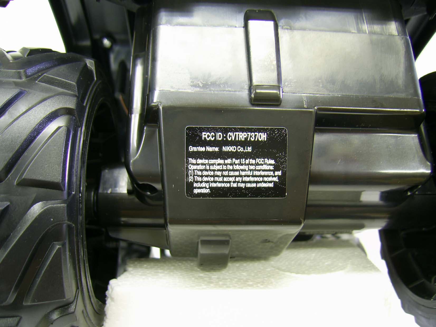
CVTRP7370H
Jul 24, 2007Radio Controlled Toy Receiver
Equipment Class
CYY - Communications Receiver used w/Pt 15 Transmitter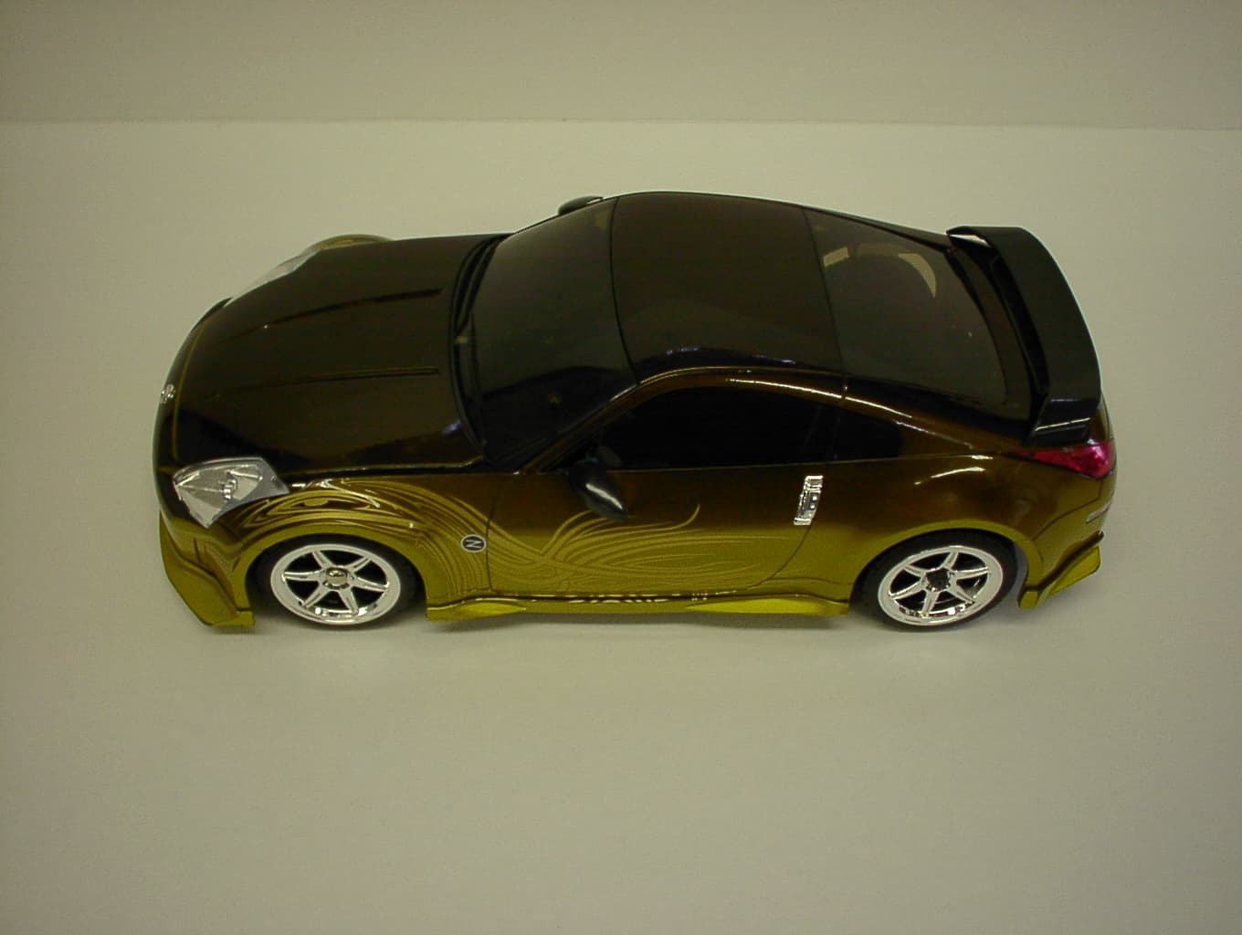
CVTRP7340H
Jan 28, 2007Radio Controlled Toy
Equipment Class
CRR - Superregenerative Receiver