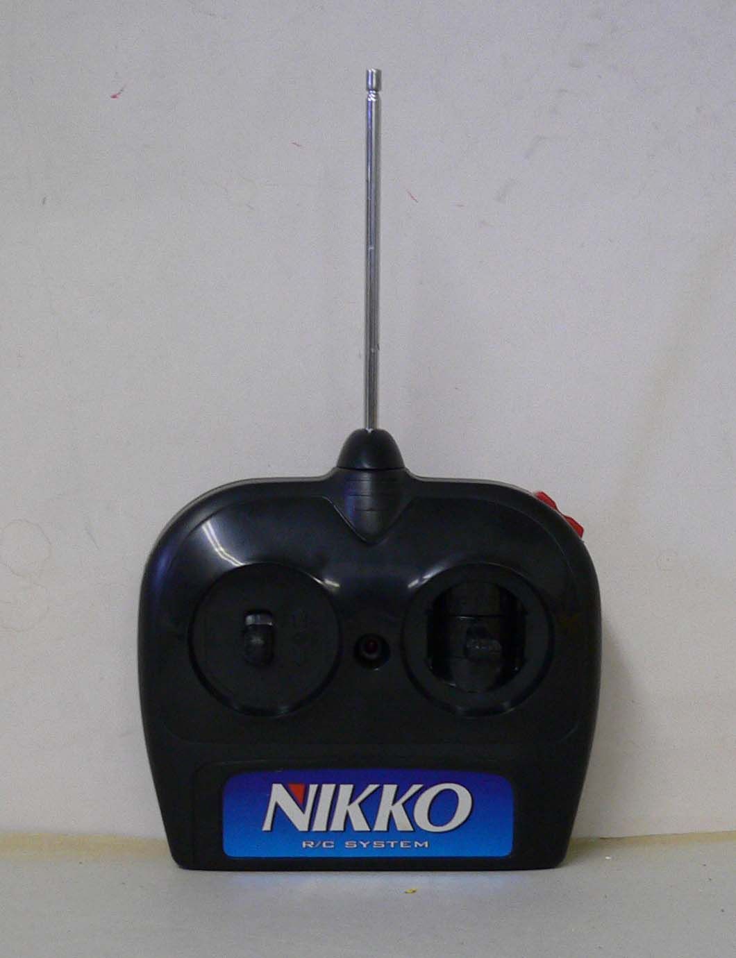
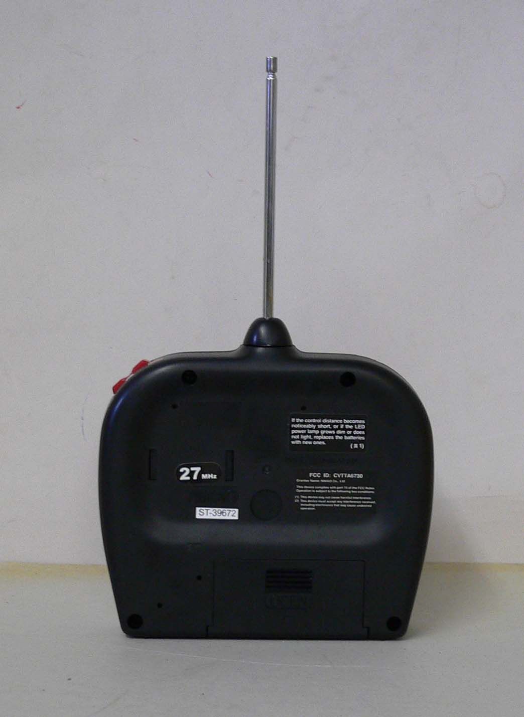
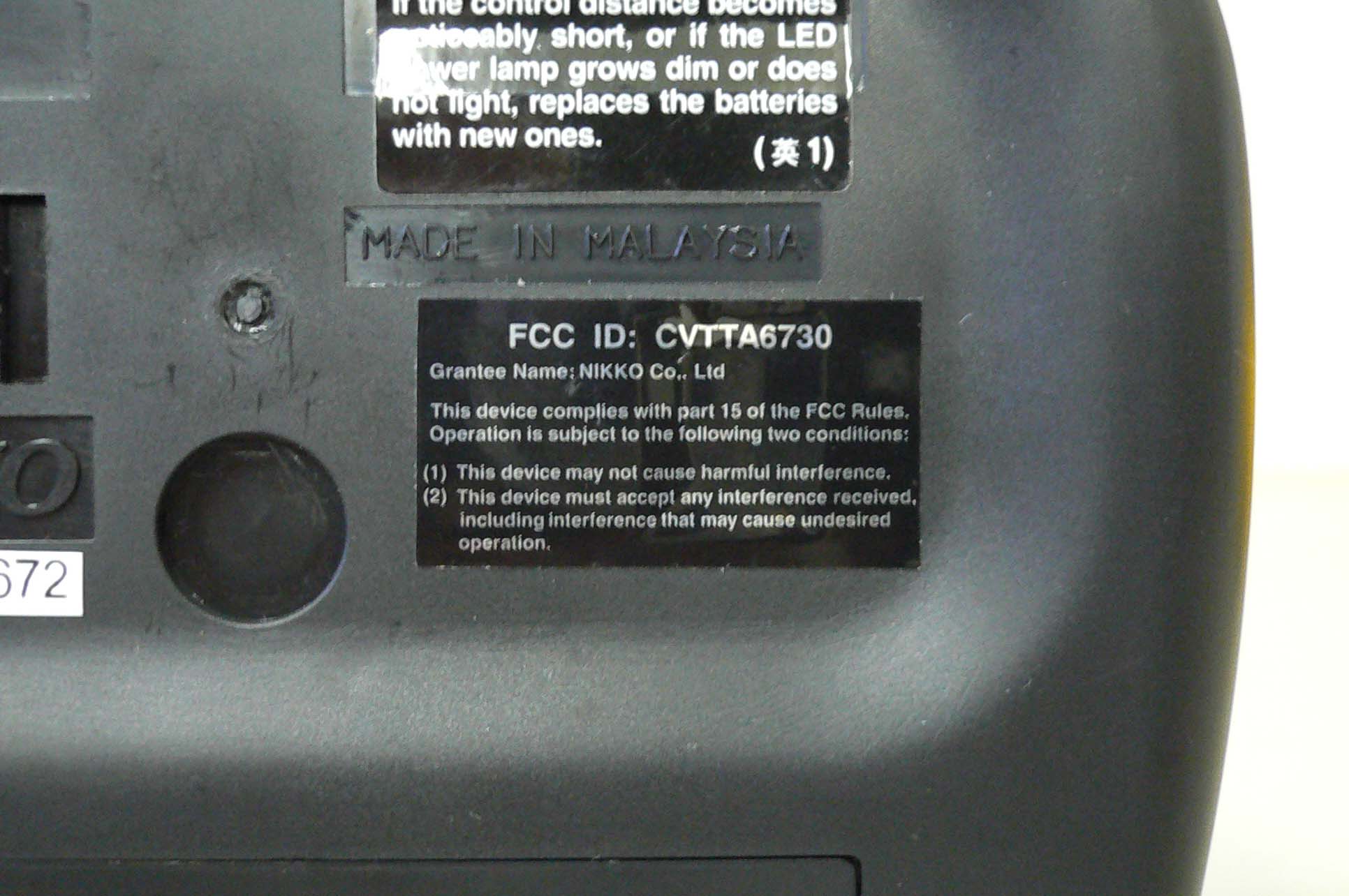
CVTTA6730Radio Controlled Toy(Transmitter)
Nikko Co Ltd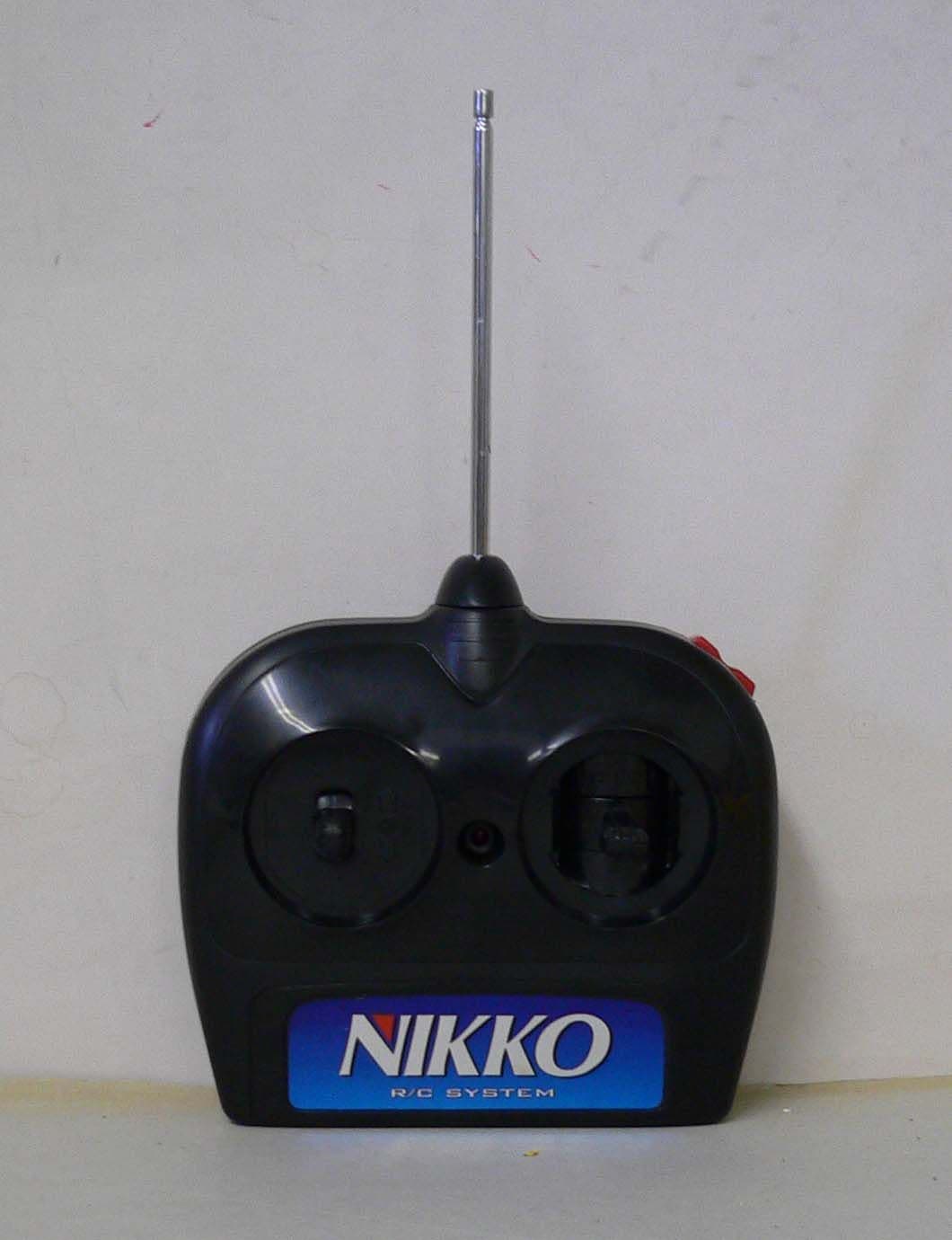
Click to zoom
Application Details
- Equipment Class
- DXX - Part 15 Low Power Communication Device Transmitter
- Date of Grant
- Jul 12, 2005
- Application Purpose
- Original Equipment
- Date of Application
- Jul 12, 2005
- Equipment Note
- Radio Controlled Toy(Transmitter)
- Frequency Range
- 26.99500000 - 27.25500000
- Company
- Nikko Co Ltd
- Country
- Japan
Documents & Files
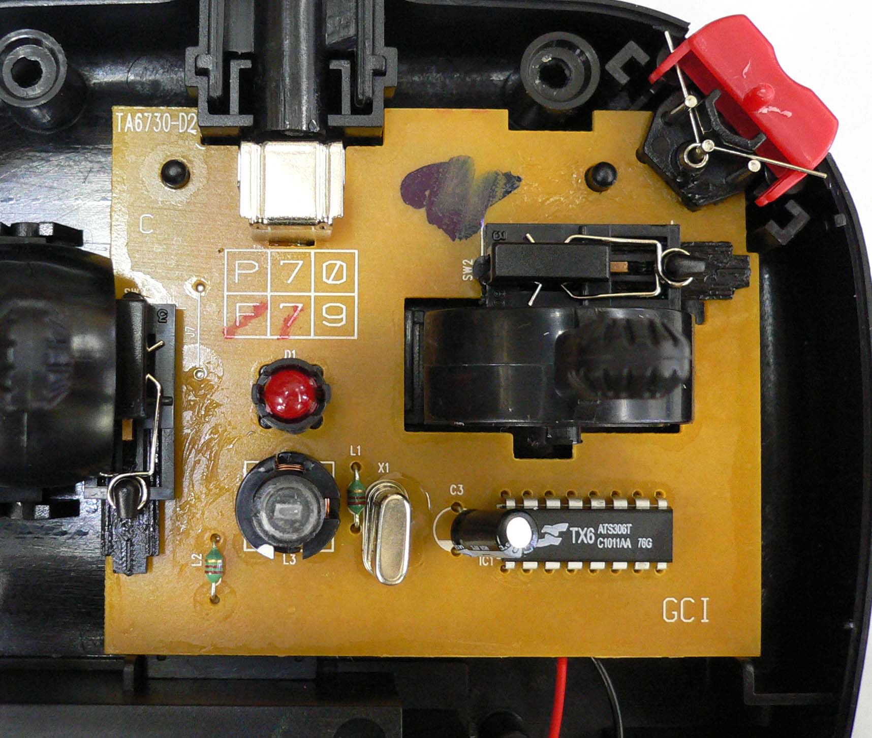
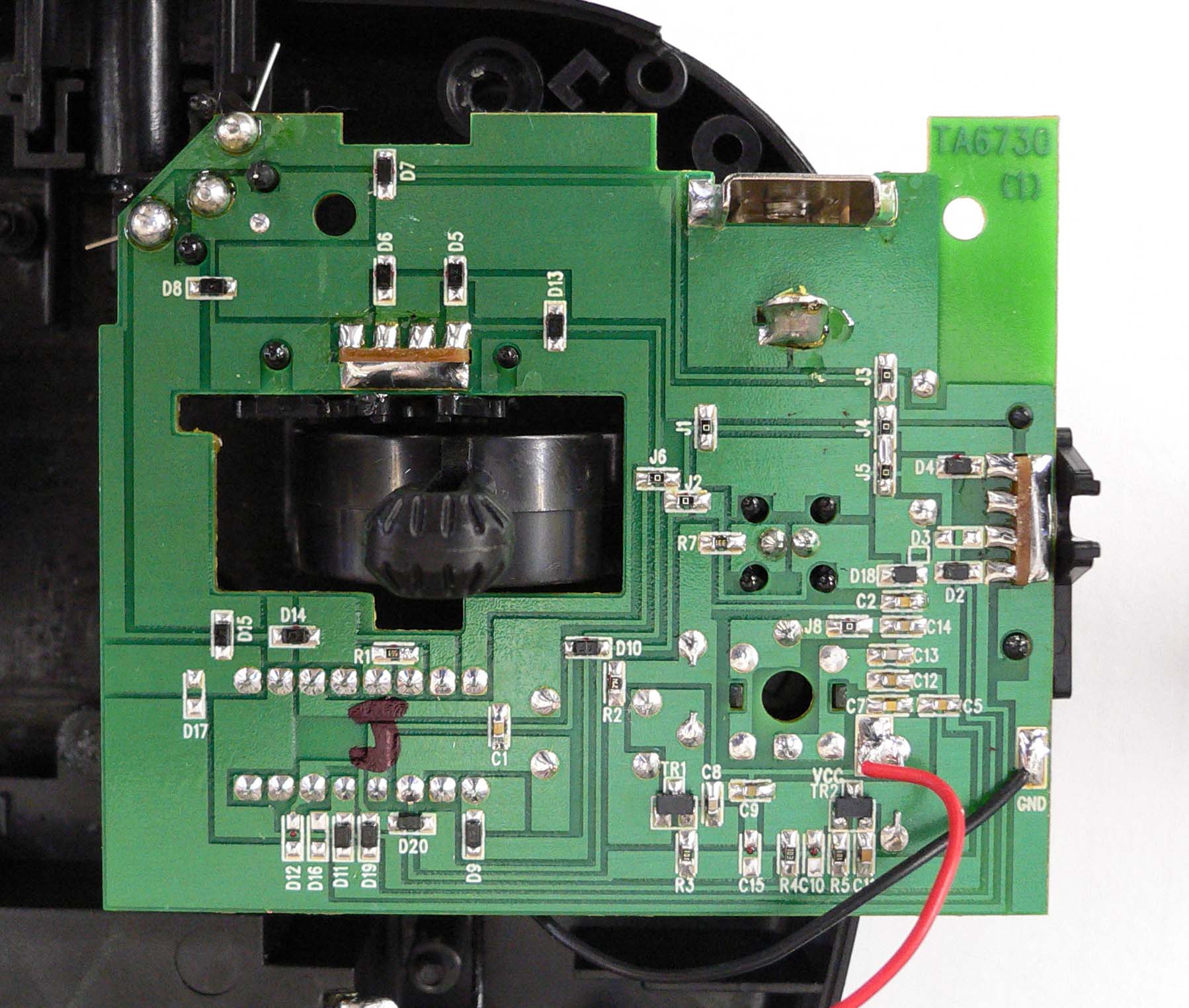
Document Text
Text extracted from the exhibit documents filed with the FCC. Open a document above to read the original.
Users Manual
1/12 Radio Control Car NIKKO PRINTED IN MALAYSIA IMPRIME EN MALAISIE IMPRESO EN MALASIA English / Français / Español Owner's Manual Manuel du lutilisateur Manual del Propietario • Recharge the Battery Before You Start to Operate • Recargue la bateria antes de empezar a jugar • Recharger la batterie avant d'allumer ATTENTTION: JOUET ELECTRIQUE Non recommandé pour les enfants de moins de 8 ans. Comme aves tous les appareils électriques, des précaut ons doivent être observées pendant la manipulation et l'emploi pour éviter toute décharge électrique. Entrée: secteur 120 VAC, 60 Hz seulement Sortie: 12VDC 200mA PARENTS ATTENTION Il est recommandé de vérifier périodiquement l'absence de risque potentiel sur ce jouet et tous les accessoires et de réparer o remplacer les pieces potentieliement dangereuses. FEATURES PRECAUCÓN: JUGETE ELÉCTRICO No recomendado para niños de menos de 8 años de edad. AL igual que con todos los productos eléctricos, para evitar un shock eléctrico, se deben observar precauciones especiales al manipular y usar este juguete. Entrada: Solamente 120 VAC, 60 Hz. Salida: 12 VDC, 200mA ATENCIÓN PADRES Se recomienca que este juguete y todos sus accesorios sean examinados periódicamente para tratar de encontrar peligros potenciales provocados por piezas que necesiten ser reparadas o cambiadas. CARACTERISTIQUES CARACTERÍSTICAS 9.6 V KMNA-120125 NMO-300505 NECESIDADES DE PILAS PILE/BATTERIE BATTERY REQUIREMENTS: Vehicle : Ni-Cd battery energy pack (9.6V, 600-650mAh) Transmitter : 1 x 9V(006P)battery Véhicule : Batterie autonome Ni-Cd (9,6V, 600-650mAh)rechargeable Emetteur : 1 pile 006p(9V) Vehiculo : Bateria de pilas do Ni-Cd "energy pack" de (9,6V, 600-650mAh) Transmisor : 1 pila de 9 V (006P) 2-channel full function: Forward, reverse, left/ right turn and stop. Transform action. Rear wheel differential gear. Front & rear suspension. Working headlight. Please read carefully before starting to operate. Keep the display box and the manual for future reference. Warning! Use under the direct supervision of an adult Actual product may vary from illustration of this manual. Lea estas instrucciones detenidamente antes de la utilización. Guardar la caja y el manual para su consulta en el futuro. Precautión! Úselo bajo la supervisión diercta de un adulto. El producto real puede diferir ligeramente de las ilustraciones. Lisez attentivement ce manuel avant de commencer à utiliser le véhicule. Conservez la boîte d'exposition et le manuel pour toute référence ultérieure. Attention! A utiliser sous la supervision directe d’un adulte. La moto contenue dans l'emballage peut ne pas correspondre exactement aux illustrations. ! Toutes fonctions, 2 canaux: marche avant, arrière, virage à gauche/droite et arrèt Transformation. Fonctionnement des phares avant Funciones completas mediante dos canales: Avance, retroceso, giros a la izquierda o derecha y detención Acción de transformación. Faros que se iluminan. 120125 Morph nator ST-39672 English 2 Do not charge Battery Pack immediately after use. Wait until it has cooled before charging. Avoid short circuits. Short circuits will cause overheating, burning of the cords and other damages to the battery Pack and Charger. The Ni-Cd Battery Charger should be used for charging one Battery Pack. Do not use the Charger for charging other type of batteries and battery packs Do not use the Charger as a direct current outlet for other electrical appliances or machines. Make sure that the Battery Pack and Charger are kept out of the hands of infants and small children while charging. Do not charge near fires, where the temperature is extremely high, or where it is wet or damp. The charger will become slightly heated while charging. Allow sufficient free space around the Charger. If the power of the battery pack is weak in spite of proper charging, the batteries may be worn out from repeated use. Replace it with a new Ni-Cd battery pack. Dispose of use Ni-Cd battery packs correctly. Disconnect the supply before making or breaking connections to the battery. Only use batteries or accumulators of the recommended type or a similar type. WARNING AGAINST RECHARGING NON-RECHARGEABLE BATTERIES. Please use this battery charger only for the charge of the rechargeable battery pack. The Ni-Cd battery pack should be charged under the supervision of an adult. CAUTION RECHARGING "WARNING! USE UNDER THE DIRECT SUPERVISION OF AN ADULT." * The newly purchased Ni-Cd pack is not charged. Charge before operating. Household outlet Ni-Cd battery pack OR Charger Household outlet Charger Ni-Cd battery pack 1. Join the connector of the charger to the connector of the Ni-Cd battery pack. 2. Plug the charger into an electrical outlet. 3. Recharge for about 4-5 hours. 4. When the recharging is over, plug out the charger from the electrical outlet and detach the connectors. When playing for the first time after purchase, or after a long interval, the battery power may be weak. Even after recharging, the playing time can be relatively short. The battery will gradually regain power after 2 or 3 repetitions of usage and recharging. TOP VIEWBOTTOM VIEW NAMES OF PARTS 120125 Morph nator Transmitter antenna 3 English Pass the antenna wire through the antenna tube, then insert the tube into the antenna tube holder. If the antenna tube cannot be successfully inserted into the antenna tube holder, try holding the root of the antenna wire with fingers of one hand and extending the wire with fingers of the other hand. 1. HOW TO ATTACH ANTENNA TUBE * Note: Be careful not to pull antenna wire too strong. PREPARATION FOR STARTING OPERATION 2. HOW TO INSTALL TRANSMITTER ANTENNA Place the transmitter antenna into the antenna holder to screw it in clock-wise. Do not extend the antenna when installing. It’s dangerous. If the antenna is not screwed in securely, the vehicle may move erratically. Screw the antenna securely. Antenna wire Antenna tube Antenna tube holder 3. HOW TO INSTALL THE BATTERIES Transmitter…
Text truncated - open the document above for the full version.
Parts List/Tune Up Info
NO.TA6730 PCB.PARTS LIST 27.145MHz for CVTTA6730 NO.DESCRIPTIONCODEPARTS NAME Morph`NatorNOTE 1I.C.IC1TX6ACTION 2TRANSISTORTR12SC1623L6 or equivalent 3TR22SC1623L6 or equivalent 4DIODED 1LED:D.5mm 5D 21N4148WS or equivalent 6D 3- 7D 41N4148WS or equivalent 8D 51N4148WS or equivalent 9D 61N4148WS or equivalent 10D 71N4148WS or equivalent 11D 81N4148WS or equivalent 12D 91N4148WS or equivalent 13D101N4148WS or equivalent 14D111N4148WS or equivalent 15D12- 16D131N4148WS or equivalent 17D141N4148WS or equivalent 18D151N4148WS or equivalent 19D16- 20D17- 21D183.3V 22D191N4148WS or equivalent 23D201N4148WS or equivalent 24RESISTORR 156k 25R 2270K 26R 3100 27R 410K 28R 5100 29R 7330 30CAPACITORC 1104(C) 31C 2104(C) 32C 347(E) 33C 5104(C) 34C 7104(C) 35C 868p(C) 36C 947p(C) 37C10- 38C11103(C) 39C1247p(C) 40C13100p(C) 41C1415p(C) 42INDUCTORL 1SP 2.2uH 43L 2SP 2.2uH 44L 311.5T 45JUMPERJ 1O ohm 46J 2O ohm 47J 30 ohm 48J 40 ohm 49J 50 ohm 50J 60 ohm 51J 7- 52J 80 ohm 53EXTRA PARTSEP1X1:27.145MHz49U.type 54EP2ANT.FITTING:AH-39 55EP3SUB PCB:NO.S3 x 2 56EP4MAIN PCB:NO.TA6730 RESISTOR:1608 type chip,1/16W,±5% INDUCTOR:100mA,±10% CAPACITOR(C):Ceramic,1608 type chip,50WV,+-10% (T):Tantalum,35WV,±10% (M):Mylar,50WV[No mark=K.rank(±10%),J.rank(±5%)] (E):Electrolytic,16WV,±20% (N):Non pole Electrolytic,16WV,±20%
Test Report
JAPAN QUALITY ASSURANCE ORGANIZATION 21-25, KINUTA 1-CHOME, SETAGAYA-KU, TOKYO 157-8573 JAPAN PHONE +81-3-3416-0111, FAX +81-3-3416-9691 JQA File No. : 400-50246 Issue Date : June 27, 2005 Page 1 of 37 EMI TEST REPORT JQA File No. : 400-50246 Model No. : TA6730 Type of Equipment : Radio Controlled Toy (Transmitter) Regulations Applied : CFR 47 FCC Rules and Regulations Part 15 FCC ID : CVTTA6730 Applicant : NIKKO CO., LTD. Address : 1-7-14, Mizumoto, Katsushika-ku, Tokyo 125-0032, Japan Manufacturer : NIKKO ELECTRONICS BHD. Address : Plot 497, Prai Free Trade Zone, Prai Industrial Estate, Prai, Penang, Malaysia. 13600 Received date of EUT : June 22, 2005 Final Judgment : Passed Test results in this report are obtained in use of equipment that is traceable to National Institute of Advanced Industrial Science and Technology (AIST) of Japan and National Institute of Information and Communications Technology(NICT) of Japan. The test results only respond to the tested sample. This report should not be reproduced except in full, without the written approval of JQA EMC Engineering Dept. Testing Div. JQA File No. :400-50246 FCC ID :CVTTA6730 Model No. :TA6730 Issue Date :June 27, 2005 Standard :CFR 47 FCC Rules Part 15 Page 2 of 37 JAPAN QUALITY ASSURANCE ORGANIZATION TABLE OF CONTENTS Page 1 Documentation 1.1 Test Regulation 3 1.2 General Information 3 1.3 Test Condition 4 – 8 1.4 EUT Modifications / Deviation from Standard 9 1.5 Test results 10 1.6 Summary 11 1.7 Test Configuration / Operation of EUT 12 1.8 EUT Arrangement(Drawing) 13 1.9 Preliminary Test and Test-setup (Drawings) 14 – 19 1.10 EUT Arrangement (Photographs) 20 – 21 2 Test Data 2.1 AC Power Line Conducted Emission N/A 2.2 Radiated Emission (Electric Field) 22 – 23 2.3 Frequency Stability N/A 2.4 Occupied Bandwidth 24 – 32 3 Appendix Test instruments List 33 – 37 JQA File No. :400-50246 FCC ID :CVTTA6730 Model No. :TA6730 Issue Date :June 27, 2005 Standard :CFR 47 FCC Rules Part 15 Page 3 of 37 JAPAN QUALITY ASSURANCE ORGANIZATION 1 DOCUMENTATION 1.1 TEST REGULATION FCC Rules and Regulations Part 15 Subpart A and C Intentional Radiators Test procedure : AC power line conducted emission, radiated emission, frequency stability and occupied bandwidth tests were performed according to the procedures in ANSI C63.4-2003. 1.2 GENERAL INFORMATION 1.2.1 Test facility : 1) Test Facility located at EMC Engineering Dept. Testing Div. : - No.2 and 3 Anechoic Chambers( 3 meters Site ). - Shielded Enclosure. 2) EMC Engineering Dept. Testing Div. is recognized under the National Voluntary Laboratory accreditation Program for satisfactory compliance established in title 15, Part 285 Code of Federal Regulations. NVLAP Lab Code : 200189-0 1.2.2 Description of the Equipment Under Test (EUT) : 1) Type of Equipment : Radio Controlled Toy (Transmitter) 2) Product Type : Production 3) Category : Low Power Communication Device Transmitter 4) EUT Authorization : Certification 5) FCC ID : CVTTA6730 6) Trade Name : NIKKO 7) Model No. : TA6730 8) Operating Frequency Range : 27.145 MHz 9) Highest Frequency Used in the EUT : 27.145 MHz 10) Serial No. : None 11) Date of Manufacture : None 12) Power Rating : DC 9.0V(Battery) 13) EUT Grounding : None 1.2.3 Definitions for symbols used in this test report : x - indicates that the listed condition, standard or equipment is applicable for this report. - indicates that the listed condition, standard or equipment is not applicable for this report. JQA File No. :400-50246 FCC ID :CVTTA6730 Model No. :TA6730 Issue Date :June 27, 2005 Standard :CFR 47 FCC Rules Part 15 Page 4 of 37 JAPAN QUALITY ASSURANCE ORGANIZATION 1.3 TEST CONDITION 1.3.1 The measurement of the AC Power Line Conducted Emission - was performed in the following test site. x - was not applicable. Test location : Safety & EMC Center EMC Engineering Dept. Testing Div. 21-25, Kinuta 1-chome, Setagaya-ku, Tokyo 157-8573, Japan - Shielded Enclosure - Anechoic Chamber No. 2 (portable Type) Used test instruments : Type Number of test instruments (Refer to Appendix) Test Receiver N/A Spectrum Analyzer N/A Cable N/A AMN(for EUT) N/A AMN(for Peripheral) N/A Termination N/A JQA File No. :400-50246 FCC ID :CVTTA6730 Model No. :TA6730 Issue Date :June 27, 2005 Standard :CFR 47 FCC Rules Part 15 Page 5 of 37 JAPAN QUALITY ASSURANCE ORGANIZATION 1.3.2 The measurement of the Radiated Emission(9 kHz – 30 MHz) x - was performed in the following test site. - was not applicable. Test location : Safety & EMC Center EMC Engineering Dept. Testing Div. 21-25, Kinuta 1-chome, Setagaya-ku, Tokyo 157-8573, Japan - Anechoic Chamber No. 2 (3 meters) x - Anechoic Chamber No. 3 (3 meters) Validation of Site Attenuation : 1) Last Confirmed Date : N/A 2) Interval : N/A Used test instruments : Type Number of test instruments (Refer to Appendix) Test Receiver TR06 Antenna AN01 Cable CA06 JQA File No. :400-50246 FCC ID :CVTTA6730 Model No. :TA6730 Issue Date :June 27, 2005 Standard :CFR 47 FCC Rules Part 15 Page 6 of 37 JAPAN QUALITY ASSURANCE ORGANIZATION 1.3.3 The measurement of the Radiated Emission(30 MHz – 1000 MHz) x - was performed in the following test site. - was not applicable. Test location : Safety & EMC Center EMC Engineering Dept. Testing Div. 21-25, Kinuta 1-chome, Setagaya-ku, Tokyo 157-8573, Japan - Anechoic Chamber No. 2 (3 meters) x - Anechoic Chamber No. 3 (3 meters) Validation of Site Attenuation : 1) Last Confirmed Date :March, 2005 2) Interval :1 year Used test instruments : Type Number of test instruments (Refer to Appendix) Test Receiver TR06 Antenna AN07, AN09 Cable CA02 RF Amplifier N/A JQA File No. :400-50246 FCC ID :CVTTA6730 Model No. :TA6730 Issue Date :June 27, 2005 Standard :CFR 47 FCC Rules Part 15 Page 7 of 37 JAPAN QUALITY ASSURANCE ORGANIZATION 1.3.4 The measurement of the Radiated Emission(Above 1000 MHz) - was performed in the following test site. x - was not applicable. Test location : Safety & EMC Center EMC Engineering Dept. Testing Div. 21-25, Ki…
Text truncated - open the document above for the full version.
Test Setup Photos
JQA File No. :400-50246 FCC ID :CVTTA6730 Model No. :TA6730 Issue Date :June 27, 2005 Standard :CFR 47 FCC Rules Part 15 Page 20 of 37 JAPAN QUALITY ASSURANCE ORGANIZATION 1.10 TEST ARRANGEMENT (PHOTOGRAPHS) PHOTOGRAPHS OF EUT CONFIGURATION FOR RADIATED EMISSIONS MEASUREMENT Photograph present configuration with maximum emission JQA File No. :400-50246 FCC ID :CVTTA6730 Model No. :TA6730 Issue Date :June 27, 2005 Standard :CFR 47 FCC Rules Part 15 Page 21 of 37 JAPAN QUALITY ASSURANCE ORGANIZATION
Contact Information
Applicant
Minori Oohira
81-3 3609-0900Fax: 81 3-3609-1033
Test Firm
Japan Qlty. Assur. Org. Kitakansai Testing CenterHiroyuki Nakamura
Technical Specifications
| # | Rule Parts | Frequency Range | Power Output |
|---|---|---|---|
| 1 | 15C | 26.995 MHz - 27.255 MHz | - |
Other Applications from Nikko Co Ltd
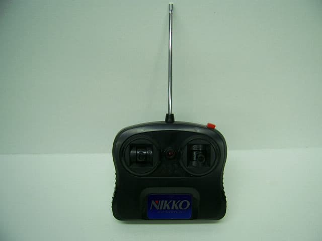
CVTTA7752
Mar 12, 2008Radio Controlled Toy
Equipment Class
DXX - Part 15 Low Power Communication Device Transmitter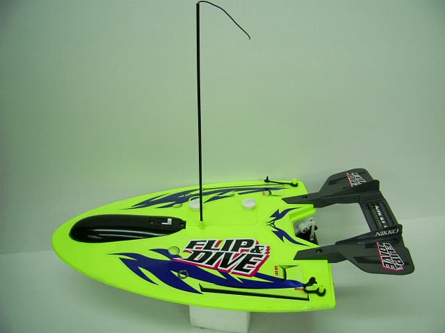
CVTRA4040H
Mar 12, 2008Radio Controlled Toy
Equipment Class
CYY - Communications Receiver used w/Pt 15 Transmitter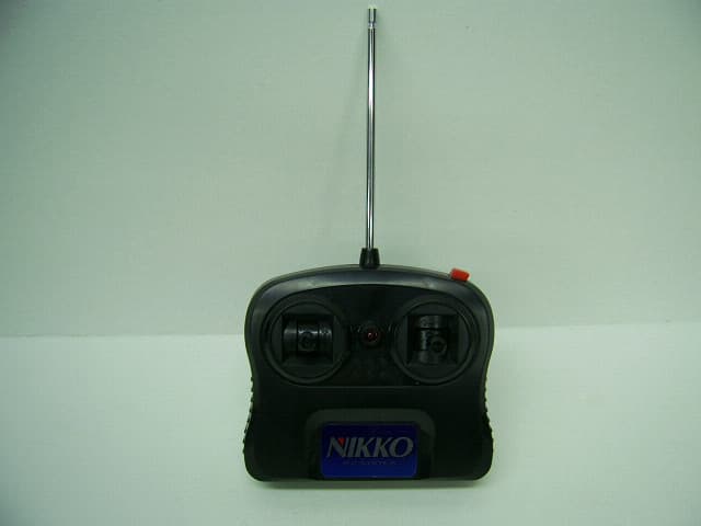
CVTTP7752H
Mar 12, 2008Radio Controlled Toy
Equipment Class
DXX - Part 15 Low Power Communication Device Transmitter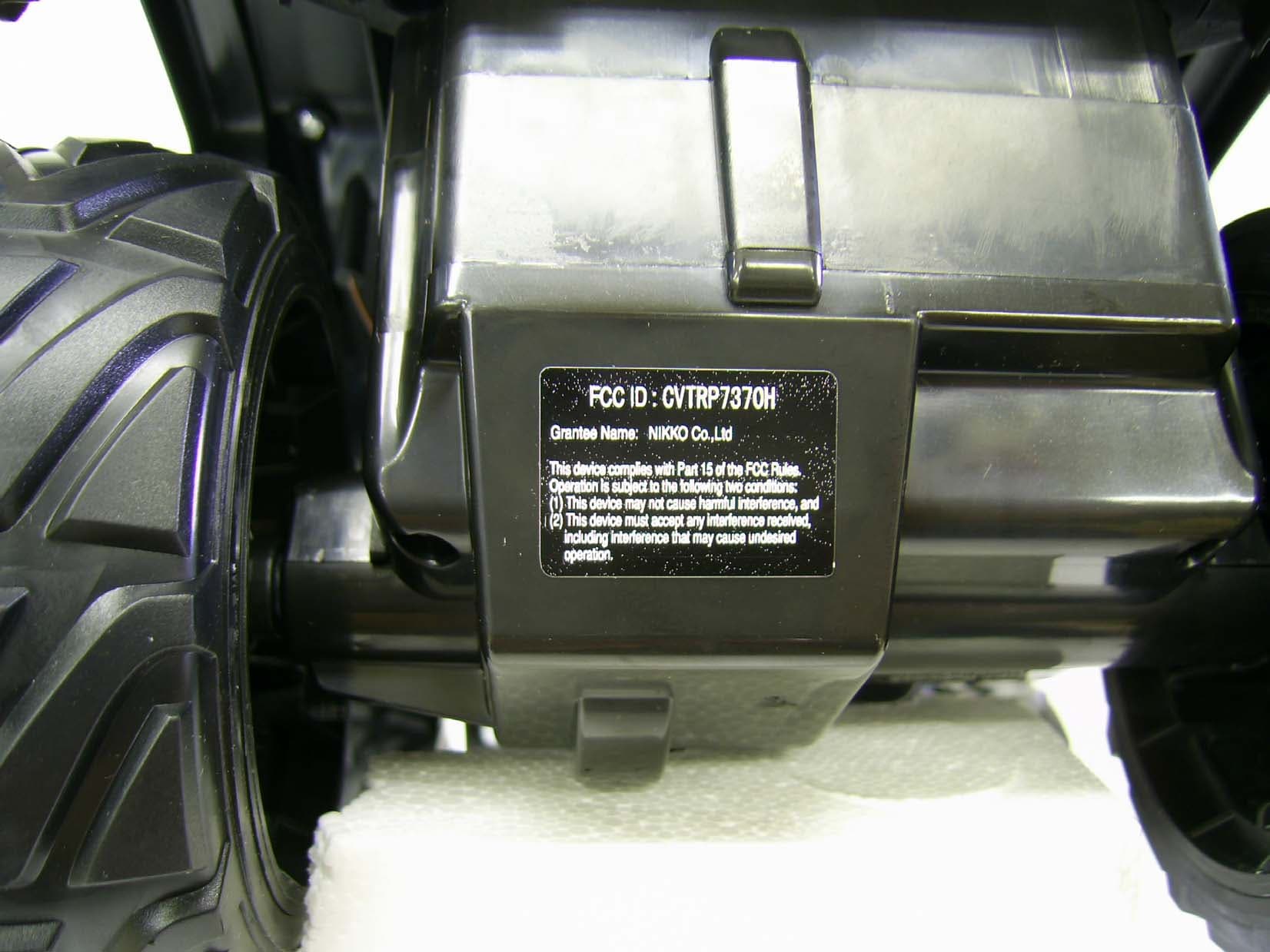
CVTRP7370H
Jul 24, 2007Radio Controlled Toy Receiver
Equipment Class
CYY - Communications Receiver used w/Pt 15 Transmitter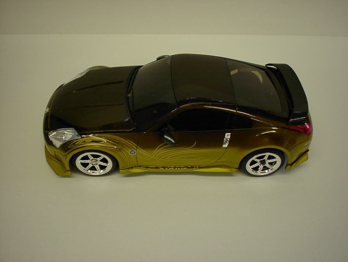
CVTRP7340H
Jan 28, 2007Radio Controlled Toy
Equipment Class
CRR - Superregenerative Receiver