CVTTH9800Radio Controlled Toy(Transmitter)
Nikko Co Ltd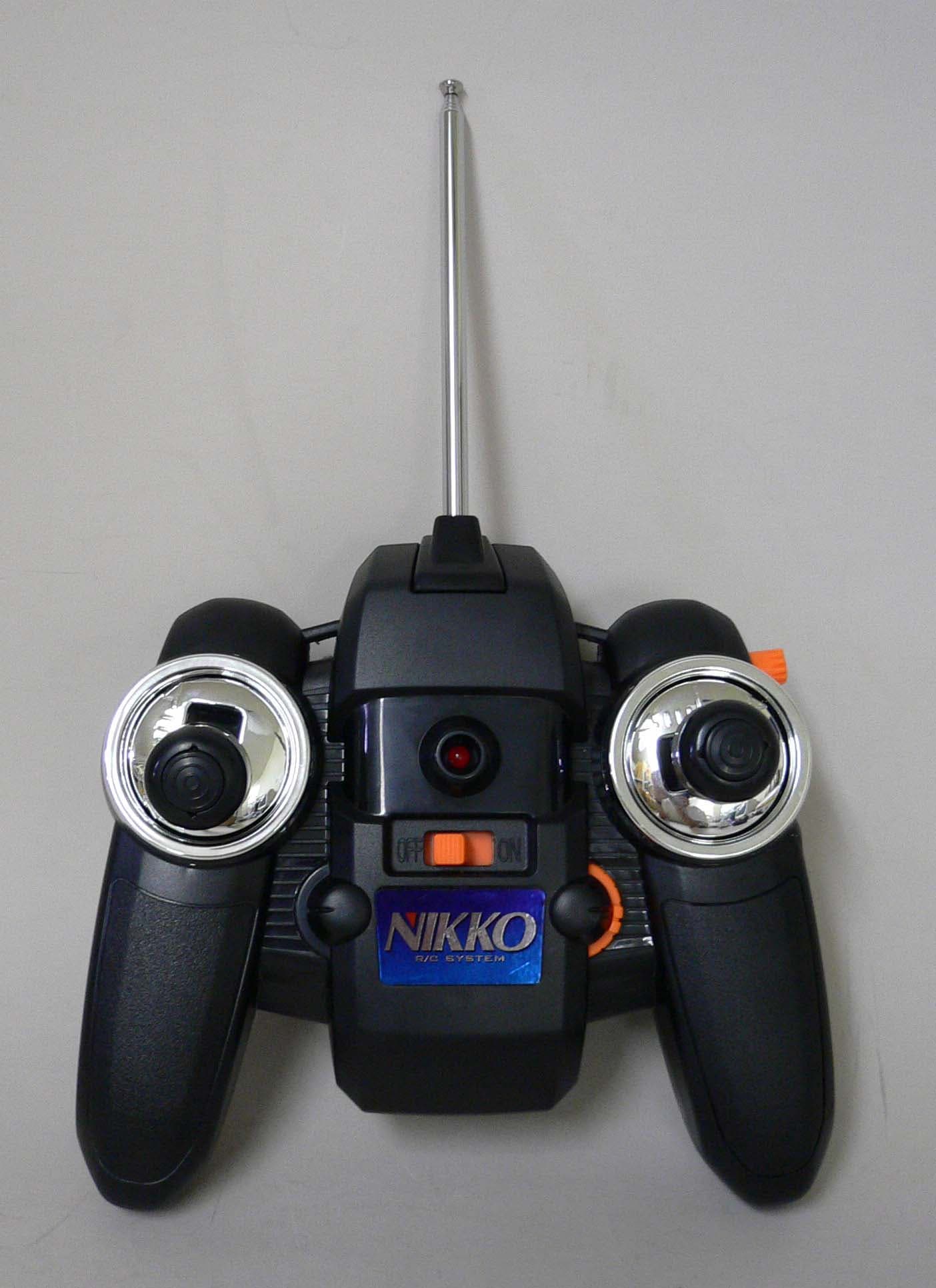
Click to zoom
Application Details
- Equipment Class
- DXX - Part 15 Low Power Communication Device Transmitter
- Date of Grant
- Sep 06, 2005
- Application Purpose
- Original Equipment
- Date of Application
- Sep 06, 2005
- Equipment Note
- Radio Controlled Toy(Transmitter)
- Frequency Range
- 26.99500000 - 27.19500000
- Company
- Nikko Co Ltd
- Country
- Japan
Documents & Files
Document Text
Text extracted from the exhibit documents filed with the FCC. Open a document above to read the original.
Users Manual
KMGN-510031B-R NMO-060705 start n'utilisez pas 1 12 12 12 12 9.6 V Les illustrations du produit figurant dans ce manuel peuvent différer du produit que vous avez acheté. El producto real puede diferir ligeramente de las ilustraciones. Zum Nikko Hubschrauber gehört ein Ni-MH Akku und ein spezielles Akku Ladegerät. Der Sender benötigt 6 Batterien im Format AA 1,5V (LR6). Das Akku Ladegerät ist für den Anschluß an die Zigarettenanzünderbuchse in Ihrem PKW oder für den Batteriebetrieb geeignet (benötigt 8 Batterien im Format D Mono 1,5V (LR20). • Vor dem Spielen mit diesem Modell machen Sie sich bitte gründlich mit dem Inhalt der Bedienungsanleitung vertraut. • Diese Bedienungsanleitung stets griffbereit zum späteren Nachschlagen aufbewahren. • Das Produkt ist nicht geeignet für Kinder unter 12 Jahren. • Nur unter der direkten Aufsicht eines Erwachsenen benutzen. Das Aussehen des Produkts kann sich etwas von den Abbildungen unterscheiden. The radio control Helicopter kit contains an 9.6-volt battery and a special battery charger. The transmitter operates on 6 size-AA alkaline batteries. If you can't use the cigarette lighter of your car as the power source for the charger, you will need to install 8 size-D alkaline batteries in the charger. The product shown in this manual may look different from the one you have purchased. When playing for the first time after purchase, or after a long interval, the battery power may be weak. Even after recharging, the flying time can be relatively short. The battery will gradually regain power after 2 or 3 repetitions of usage and recharging. Also, if you keep the radio control helicopter power switch turned ON for a long time, the battery power will be discharged. Make sure to turn OFF the power switch immediately after use. BATTERY CHARACTERISTICS AND RECHARGING TIPS Once the battery pack is cooled, it begins to lose power and the powered flying time will become shorter. In such a case, recharge the battery pack once again and use it while it is warm. Lorsque le pack batterie est refroidi, il va commencer à perdre de la puissance, et le temps de vol sera plus court. Dans ce cas, rechargez le pack batterie de nouveau, et utilisez le lorsqu'il est tiède Sobald der Akku abkühlt, beginnt er an Leistung zu verlieren, was seine Nutzleistungszeit für den Flug verkürzen wird. In diesem Fall laden Sie das Akku erneut auf und benutzen Sie ihn, während er noch warm ist. Una vez se enfría la batería, empieza a perder energía y el tiempo de vuelo se acorta. En ese caso, recarge de nuevo el pack de baterías y úselo mientras esté caliente. Op het moment dat de batterij afgekoeld is, verliest de batterij kracht en dan zal de vliegtijd korter worden. Indien dit het geval is, moet je de batterij opnieuw opladen en gebruiken als het nog warm is. OFF CARACTERISTIQUES DE LA BATTERIE, ET CONSEILS POUR LA RECHARGER Lorsque vous jouez avec l'hélicoptère pour la 1ère fois après son achat, ou bien après une longue interruption, la puissance de la batterie peut être faible. Même après avoir rechargé, le temps de vol peut être relativement court. La batterie retrouvera progressivement sa puissance après 2 ou 3 cycles de recharge et utilisation. De plus, si vous laissez l'hélicoptère en position ON pendant longtemps, la batterie sera déchargée. Assurez-vous de bien mettre le bouton en position OFF aussitôt après utilisation BATTERIEDATEN UND TIPPS ZUR AUFLADEN Wenn Sie zum ersten Mal nach dem Kauf oder nach einer langen Betriebspause spielen, kann die Batterieleistung schwach sein. Selbst nach der Aufladung kann die Flugzeit relativ kurz sein. Die Batterie wird nach 2- oder 3-maligem Gebrauch und Aufladung nach und nach ihre Gesamtleistung wieder erlangen. Die Batterie wird sich auch entladen, wenn Sie den Hauptschalter des RC Hubschrauber für längere Zeit eingeschaltet lassen. Stellen Sie sicher, dass der Hauptschalter direkt nach dem Gebrauch ausgeschaltet wird. CARACTERÍSTICAS DE LA BATERÍA Y CONSEJOS PARA RECARGARLA. Cuando juegue por primera vez después de la compra, o después de un periodo largo de inactividad, la energía de la batería puede ser débil. Incluso después de recargarla, el tiempo de vuelo puede ser relativamente corto. La batería irá incrementando gradualmente su potencia después de 2 ó 3 ciclos de uso y recarga. Por otro lado, si mantiene el interruptor del Helicóptero de Radio Control en la posición ON durante mucho tiempo, la batería se irá descargando. Asegúrese de colocar el interruptor en OFF inmediatamente después de usarlo. KENMERKEN VAN DE BATTERIJ EN OPLAADTIPS Wanneer er voor de eerste keer na de aankoop, of na een lange periode met de Sky Watcher gespeeld wordt, kan het zijn dat de batterijen zwak zijn. Zelfs na het opladen, kan de vliegtijd relatief kort zijn. De batterij zal na 2 of 3 keer laden en spelen, zijn kracht terug krijgen. Ook wanneer de radiografisch bestuurbare helicopter power knop voor een lange tijd op "ON" staat, kan de batterij leeg lopen. Wees er zeker van dat de power knop direct na het gebruik weer op "OFF" gezet wordt. 2 When flying radio control Helicopter, use a Ni-Mh battery pack which has just been charged and is still warm. 3 This helicopter and swash plate are mechanically designed to slightly tilt to the right. It is not a defective product. Cet hélicoptère est conçu pour s'incliner vers la droite. C'est normal pour un hélicoptère. Ce n'est pas une anomalie du produit. Dieser Hubschrauber ist so ausgelegt, dass er eine für ihn natürliche Rechtsneigung aufweist. Dabei handelt es sich also um ein Gerätemerkmal des Hubschraubers und nicht um einen Gerätedefekt. Este helicóptero está diseñado para girar hacia la derecha. Es una decisión tomada al diseñar el aparato. No es un producto defectuoso. Deze helikopter helt enigszins naar rechts. Dit is eigen aan het ontwerp van een helikopter. Het is geen defect van dit product. 1 2 If the main rotor blades turn upward as illustrated due to the impact from the hard landing or other r…
Text truncated - open the document above for the full version.
Operational Description
TH9800 CIRCUIT EXPLANATION (FCC ID:CVTTH9800) 1)TR3 forms the power circuit for control IC 2)TR1 forms the Radio Frequency oscillator. 3)Control IC read the voltage of each VR, and then creates a control signal. Then,a control signal outputted in the modulation circuit. 4)The Amplitude Modulation of the Radio Frequency is performed in TR2 by placing the waves on Audio Frequency. 5)AM. waves are output into the collector of TR2,passed through the filter, and is transmitted from the Antenna.
Parts List/Tune Up Info
NO.TH9800 PCB.PARTS LIST FCC ID : CVTTH9800 NO.DESCRIPTIONCODEPARTS NAMENOTE 1I.C.IC 1HT46R47SOP 2TRANSISTORTR12SC1623 or equivalent 3TR22SC1623 or equivalent 4TR32SC1623 or equivalent 5TR42SC1623 or equivalent 6TR52SC1623 or equivalent 6TR62SC1623 or equivalent 7DIODED15.6V(ZENER) 8D21N4148 9D3LED5mm 10D45.1V(ZENER) 11D54.3V(ZENER) 12RESISTORR1- 13R2- 14R3- 15R4220K 16R510K 17R61K 18R71K 19R810K 20R96.8K 21R101.8K ohm 22R111K ohm 23R1239K 24R13470K 25R14100 26R15- 27R16220 28R17100 29R18270 30R1910K 31R206.8K 32V.RESISTORVR1VR:5KB 33VR2VR:5KB 34VR3VR:F-09KN3 5KB 35VR4F-805SX-TR B5K 36VR510K(fix resistor) 37VR6SVR:3KB-313 38VR7SVR:3KB-313 39VR8SVR:30KB-313 40CAPACITORC1103(C) 41C2104(C) 42C3105(C) 43C4102(C) 44C5102(C) 45C6102(C) 46C747p(C) 47C847p(C) 48C947p(C) 49C1047p(C) 50C11100p(C) 51C1215p(C) 52C13103(C) 53C14102(C) 54C15102(C) 55C16103(C) 56C17104( C) 57C18223( C ) 58INDUCTORL1SP 2.2uH 59L2SP 2.2uH 60L411.5T 61JUMPERJ10 ohm 62EXTRA PARTSEP1X1: 26.995Mhz, 27.195Mhz 63EP2X3:4MHz 64EP3PCB:NO.TH9800 65EP4S1:2P-2T 66EP5S2: 0 Ohm 67EP6S3: - 68EP7S4: 0 ohm 68EP8Wire: 40mm RESISTOR:No mark=1/4W,•}5% INDUCTOR:100mA,•}10% CAPACITOR (C):Ceramic,50WV,+80-20% (T):Tantalum,35WV,•}10% (M):Mylar,50WV[No mark=K.rank(•}10%),J.rank(•}5%)] (E):Electrolytic,16WV,•}20% (N):Non pole Electrolytic,16WV,•}20%
Test Report
JAPAN QUALITY ASSURANCE ORGANIZATION 21-25, KINUTA 1-CHOME, SETAGAYA-KU, TOKYO 157-8573 JAPAN PHONE +81-3-3416-0111, FAX +81-3-3416-9691 JQA File No. : 400-50297 Issue Date : July 26, 2005 Page 1 of 38 EMI TEST REPORT JQA File No. : 400-50297 Model No. : TH9800 Type of Equipment : Radio Controlled Toy (Transmitter) Regulations Applied : CFR 47 FCC Rules and Regulations Part 15 FCC ID : CVTTH9800 Applicant : NIKKO CO., LTD. Address : 1-7-14, Mizumoto, Katsushika-ku, Tokyo 125-0032, Japan Manufacturer : NIKKO ELECTRONICS BHD. Address : Plot 497, Prai Free Trade Zone, Prai Industrial Estate, 13600 Prai, Penang, Malaysia. Received date of EUT : July 13, 2005 Final Judgment : Passed Test results in this report are obtained in use of equipment that is traceable to National Institute of Advanced Industrial Science and Technology (AIST) of Japan and National Institute of Information and Communications Technology(NICT) of Japan. The test results only respond to the tested sample. This report should not be reproduced except in full, without the written approval of JQA EMC Engineering Dept. Testing Div. JQA File No. :400-50297 FCC ID :CVTTH9800 Model No. :TH9800 Issue Date :July 26, 2005 Standard :CFR 47 FCC Rules Part 15 Page 2 of 38 JAPAN QUALITY ASSURANCE ORGANIZATION TABLE OF CONTENTS Page 1 Documentation 1.1 Test Regulation 3 1.2 General Information 3 1.3 Test Condition 4 – 8 1.4 EUT Modifications / Deviation from Standard 9 1.5 Test results 10 1.6 Summary 11 1.7 Test Configuration / Operation of EUT 12 1.8 EUT Arrangement(Drawing) 13 1.9 Preliminary Test and Test-setup (Drawings) 14 – 19 1.10 EUT Arrangement (Photographs) 20 – 21 2 Test Data 2.1 AC Power Line Conducted Emission N/A 2.2 Radiated Emission (Electric Field) 22 – 23 2.3 Frequency Stability N/A 2.4 Occupied Bandwidth 24 – 33 3 Appendix Test instruments List 34 – 38 JQA File No. :400-50297 FCC ID :CVTTH9800 Model No. :TH9800 Issue Date :July 26, 2005 Standard :CFR 47 FCC Rules Part 15 Page 3 of 38 JAPAN QUALITY ASSURANCE ORGANIZATION 1 DOCUMENTATION 1.1 TEST REGULATION FCC Rules and Regulations Part 15 Subpart A and C Intentional Radiators Test procedure : AC power line conducted emission, radiated emission, frequency stability and occupied bandwidth tests were performed according to the procedures in ANSI C63.4-2003. 1.2 GENERAL INFORMATION 1.2.1 Test facility : 1) Test Facility located at EMC Engineering Dept. Testing Div. : - No.2 and 3 Anechoic Chambers( 3 meters Site ). - Shielded Enclosure. 2) EMC Engineering Dept. Testing Div. is recognized under the National Voluntary Laboratory accreditation Program for satisfactory compliance established in title 15, Part 285 Code of Federal Regulations. NVLAP Lab Code : 200189-0 1.2.2 Description of the Equipment Under Test (EUT) : 1) Type of Equipment : Radio Controlled Toy (Transmitter) 2) Product Type : Production 3) Category : Low Power Communication Device Transmitter 4) EUT Authorization : Certification 5) FCC ID : CVTTH9800 6) Trade Name : NIKKO 7) Model No. : TH9800 8) Operating Frequency Range : 26.995 MHz 9) Highest Frequency Used in the EUT : 26.995 MHz 10) Serial No. : None 11) Date of Manufacture : None 12) Power Rating : DC 3.0V(size “AA” Battery) 13) EUT Grounding : None 1.2.3 Definitions for symbols used in this test report : x - indicates that the listed condition, standard or equipment is applicable for this report. - indicates that the listed condition, standard or equipment is not applicable for this report. JQA File No. :400-50297 FCC ID :CVTTH9800 Model No. :TH9800 Issue Date :July 26, 2005 Standard :CFR 47 FCC Rules Part 15 Page 4 of 38 JAPAN QUALITY ASSURANCE ORGANIZATION 1.3 TEST CONDITION 1.3.1 The measurement of the AC Power Line Conducted Emission - was performed in the following test site. x - was not applicable. Test location : Safety & EMC Center EMC Engineering Dept. Testing Div. 21-25, Kinuta 1-chome, Setagaya-ku, Tokyo 157-8573, Japan - Shielded Enclosure - Anechoic Chamber No. 2 (portable Type) Used test instruments : Type Number of test instruments (Refer to Appendix) Test Receiver N/A Spectrum Analyzer N/A Cable N/A AMN(for EUT) N/A AMN(for Peripheral) N/A Termination N/A JQA File No. :400-50297 FCC ID :CVTTH9800 Model No. :TH9800 Issue Date :July 26, 2005 Standard :CFR 47 FCC Rules Part 15 Page 5 of 38 JAPAN QUALITY ASSURANCE ORGANIZATION 1.3.2 The measurement of the Radiated Emission(9 kHz – 30 MHz) x - was performed in the following test site. - was not applicable. Test location : Safety & EMC Center EMC Engineering Dept. Testing Div. 21-25, Kinuta 1-chome, Setagaya-ku, Tokyo 157-8573, Japan x - Anechoic Chamber No. 2 (3 meters) - Anechoic Chamber No. 3 (3 meters) Validation of Site Attenuation : 1) Last Confirmed Date : N/A 2) Interval : N/A Used test instruments : Type Number of test instruments (Refer to Appendix) Test Receiver TR06 Antenna AN01 Cable CA06 JQA File No. :400-50297 FCC ID :CVTTH9800 Model No. :TH9800 Issue Date :July 26, 2005 Standard :CFR 47 FCC Rules Part 15 Page 6 of 38 JAPAN QUALITY ASSURANCE ORGANIZATION 1.3.3 The measurement of the Radiated Emission(30 MHz – 1000 MHz) x - was performed in the following test site. - was not applicable. Test location : Safety & EMC Center EMC Engineering Dept. Testing Div. 21-25, Kinuta 1-chome, Setagaya-ku, Tokyo 157-8573, Japan x - Anechoic Chamber No. 2 (3 meters) - Anechoic Chamber No. 3 (3 meters) Validation of Site Attenuation : 1) Last Confirmed Date :March, 2005 2) Interval :1 year Used test instruments : Type Number of test instruments (Refer to Appendix) Test Receiver TR06 Antenna AN07, AN09 Cable CA02 RF Amplifier N/A JQA File No. :400-50297 FCC ID :CVTTH9800 Model No. :TH9800 Issue Date :July 26, 2005 Standard :CFR 47 FCC Rules Part 15 Page 7 of 38 JAPAN QUALITY ASSURANCE ORGANIZATION 1.3.4 The measurement of the Radiated Emission(Above 1000 MHz) - was performed in the following test site. x - was not applicable. Test location : Safety & EMC Center EMC Engineering Dept. Testing Div.…
Text truncated - open the document above for the full version.
Test Setup Photos
JQA File No. :400-50297 FCC ID :CVTTH9800 Model No. :TH9800 Issue Date :July 26, 2005 Standard :CFR 47 FCC Rules Part 15 Page 20 of 38 JAPAN QUALITY ASSURANCE ORGANIZATION 1.10 TEST ARRANGEMENT (PHOTOGRAPHS) PHOTOGRAPHS OF EUT CONFIGURATION FOR RADIATED EMISSIONS MEASUREMENT Photograph present configuration with maximum emission JQA File No. :400-50297 FCC ID :CVTTH9800 Model No. :TH9800 Issue Date :July 26, 2005 Standard :CFR 47 FCC Rules Part 15 Page 21 of 38 JAPAN QUALITY ASSURANCE ORGANIZATION PHOTOGRAPHS OF EUT CONFIGURATION FOR RADIATED EMISSIONS MEASUREMENT Photograph present configuration with maximum emission
Contact Information
Applicant
Minori Oohira
81-3 3609-0900Fax: 81 3-3609-1033
Test Firm
Japan Qlty. Assur. Org. Safety & EMC CtrHideki Kajiwara
Technical Specifications
| # | Rule Parts | Frequency Range | Power Output |
|---|---|---|---|
| 1 | 15C | 26.995 MHz - 27.195 MHz | - |
Other Applications from Nikko Co Ltd
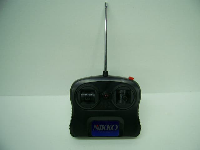
CVTTA7752
Mar 12, 2008Radio Controlled Toy
Equipment Class
DXX - Part 15 Low Power Communication Device Transmitter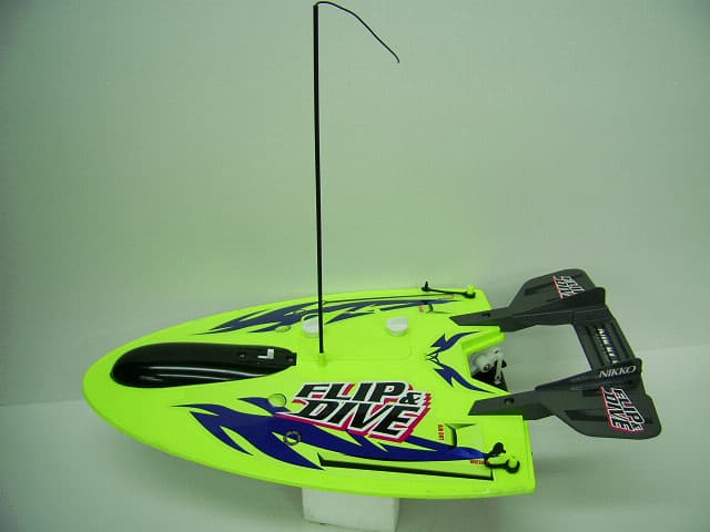
CVTRA4040H
Mar 12, 2008Radio Controlled Toy
Equipment Class
CYY - Communications Receiver used w/Pt 15 Transmitter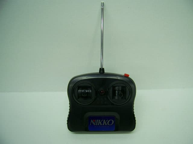
CVTTP7752H
Mar 12, 2008Radio Controlled Toy
Equipment Class
DXX - Part 15 Low Power Communication Device Transmitter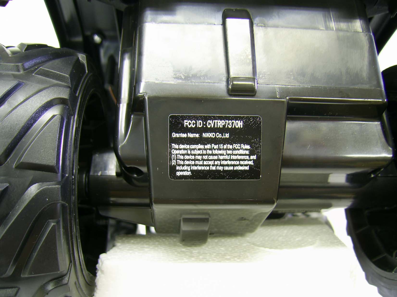
CVTRP7370H
Jul 24, 2007Radio Controlled Toy Receiver
Equipment Class
CYY - Communications Receiver used w/Pt 15 Transmitter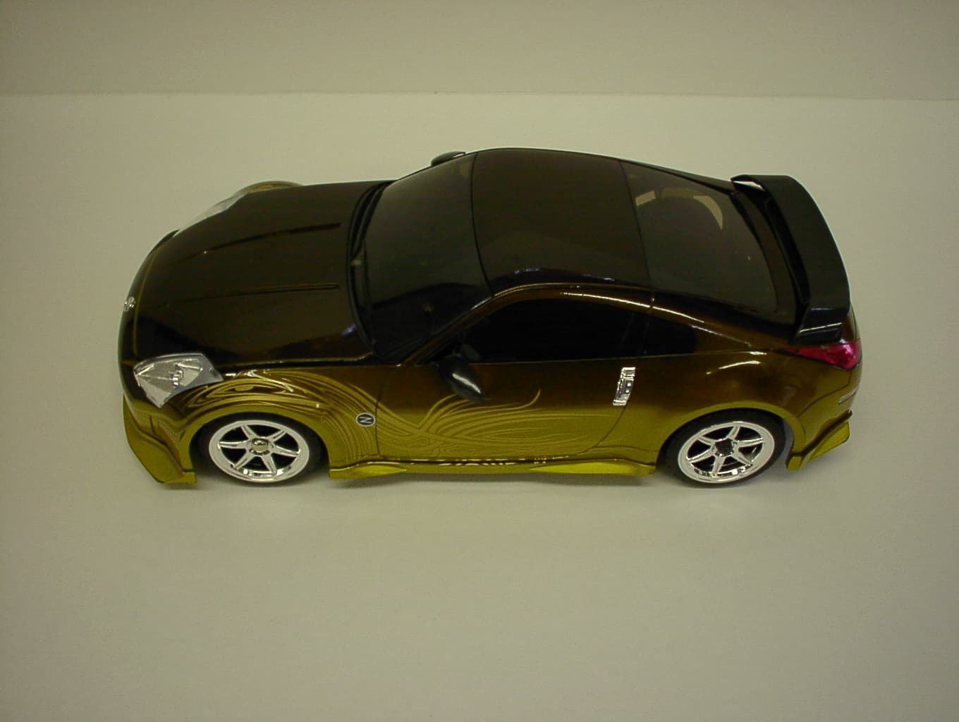
CVTRP7340H
Jan 28, 2007Radio Controlled Toy
Equipment Class
CRR - Superregenerative Receiver