CVTTP6731Radio Controlled Toy (Transmitter)
Nikko Co Ltd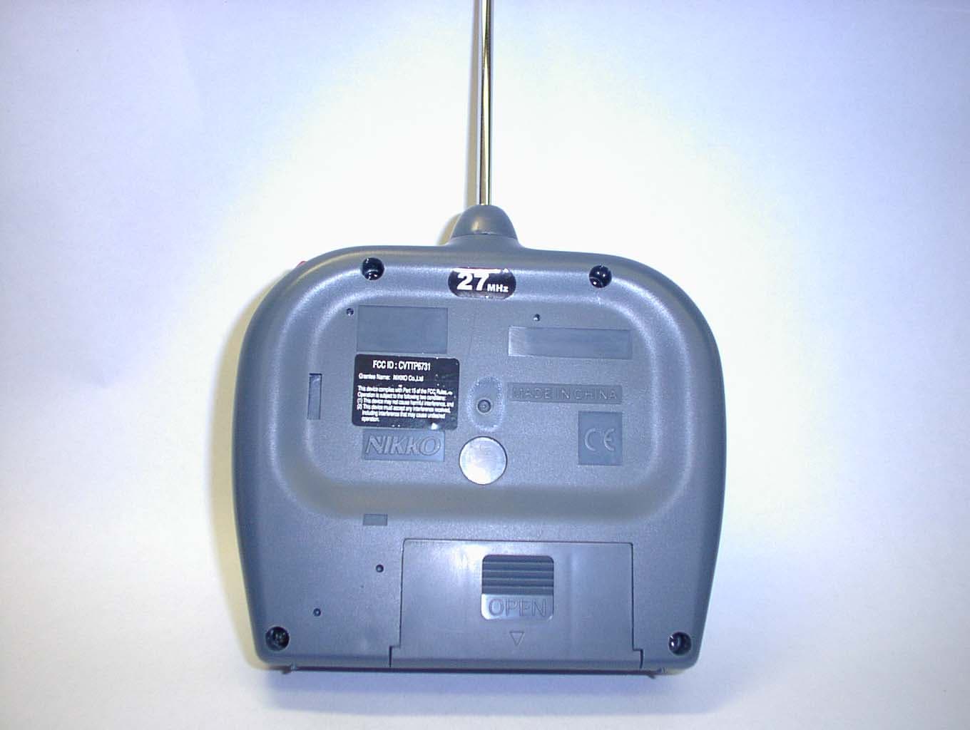
Click to zoom
Application Details
- Equipment Class
- DXX - Part 15 Low Power Communication Device Transmitter
- Date of Grant
- Sep 23, 2004
- Application Purpose
- Original Equipment
- Date of Application
- Sep 23, 2004
- Equipment Note
- Radio Controlled Toy (Transmitter)
- Frequency Range
- 27.14500000 - 27.14500000
- Company
- Nikko Co Ltd
- Country
- Japan
Documents & Files
Document Text
Text extracted from the exhibit documents filed with the FCC. Open a document above to read the original.
Users Manual
1 Please read care ful ly before start ing to operate. l "Warning! use under the direct su per vi sion of an adult. Please read care ful ly before start ing to operate. "Warning! use under the direct su per vi sion of an adult. Please read care ful ly before start ing to operate. KEEP THE DISPLAYBOX AND THE MANUAL FOR FUTURE REF ER ENCE. Use Ni-Cd battery pack(9.6V) and charger for this mod el. l l l PRINTED IN CHINA IMPRIME EN CHINE IMPRESO EN CHINA English/Français/Español l l FEATURES l BATTERY REQUIREMENTS l 2-channel full function: Forward, re verse, left/right turn and stop. 2 speed in forward running 2 speeds by transmitter op er a tion Front and rear suspension sys tem Rear wheel differential gear The Headlights lightup when running Transmitter: 1 x 9V(006P)battery 1 x NI-CD or NI-MH rechargeable bat tery pack(9.6 V) Vehicle: 1/10 RADIO CONTROL STREET CAR Manual del Propietario Manuel du lutilisateur NOT RECOMMENDED FOR CHIL DREN UN DER 8 YEARS OF AGE. AS WITH ALL ELEC TRIC PROD UCTS, PRECAU- TIONS SHOULD BE OB SERVED DUR- ING HAN DLING AND USE TO PRE- VENT ELEC TRIC SHOCK. INPUT: 120VAC, 60HZ, OUTPUT: 12VDC, 200mA ATTENTION PARENTS It is recommended that this toy and all accessories be pe ri od i cal ly ex am ined for potential haz ards and that any po ten tial haz ard ous parts be re paired or re placed. CAUTION: ELECTRIC TOY * Recharge the Battery Before you Start to Operate * Recharger la batterie avant d’allumer * Recargue la bateria antes de em- pezar a jugarpezar a jugar Owner’s Manual :[email protected]:[email protected]:[email protected]:[email protected]:[email protected] l 2 English Household outlet 1. Join the connector of the charger to the connector of the Ni-Cd battery pack (9.6 V). 2. Plug the charger into an electrical out let. 3. Recharge for about 4-5 hours. 4. When the re charg ing is over, plug out the charger from the elec tri cal outlet and de- tach the con nec tors. CAUTION: n n n n n n n n n RECHARGING Charger Ni-Cd battery pack (9.6 V)Ni-Cd battery pack (9.6 V) PREPARATION FOR START ING OP ER A TION 1. HOW TO ATTACH ANTENNA TUBE Antenna tube Antenna wire Antenna tube holder Pass the antenna wire through the antenna tube, then insert the tube into the an ten na tube holder. If the antenna tube cannot be suc- cess ful ly inserted into the antenna tube holder, try hold ing the root of the antenna wire with fingers of one hand and ex tend ing the wire with fin gers of the other hand. * Note: Be careful not to pull an- ten na wire too strong. Do not charge Battery Pack immediately after use.Wait until it is cooled before charging. Avoid short circuits. Short circuits will cause over- heating, burning of the cords and other damages to the Battery Pack and Charger. The Ni-CD Battery Charger should be used for charging one Battery Pack . Do not use the charger for charging other types of batteries and battery packs. Do not use the Charger as a direct current outlet for other electrical appliances or machines. Make sure that the Battery Pack and Charger are kept out of the hands of infants and small children while charging. Do not charge near fires, where the temperature is extremely high, or where it is wet or damp. The charger will become slightly heated while charging. Allow sufficient free space around the Charger. If the power of the battery pack is weak in spite of proper charging. The batteries may be worn out from repeated use. Replace it with a new Ni-CD battery pack. Dispose of use Ni-CD battery packs correctly. Disconnect the supply before making or breaking connections to the battery. WARNING AGAINST RECHARGING NON-RE- CHARGEABLE BATTERIES. Please use this battery charger only for the char- ger of the rechargeable battery pack. The NI-CD battery pack should be recharged un- der the supervision of an adult. n n n n OR *The newly purchased Ni-Cd pack is not charged.Recharge before operate. 3 English English When installing a Ni-Cd battery pack, make sure that the power switch of the vehicle is OFF. Vehicle Join the connectors of the vehicle and the Ni-Cd pack. Battery compartment lid 3. HOW TO INSTALL THE BAT TER IES English 3. HOW TO INSTALL THE BAT TER IES English To remove the battery lid, press the point marked “OPEN” and pull the lid down ward. One 9 volt (006P) batteryOne 9 volt (006P) battery Install battery making sure that (+) and (-) poles are positioned properly. * Dispose the used batteries sep a rate ly from other trash. Transmitter 2. HOW TO INSTALL TRANS MIT TER AN TEN NA Place the transmitter an ten na into the antenna hold er to screw it in clock- wise. Don’t install the antenna ex tend ed. It’s dangerous. If the antenna is not screwed in se- cure ly, the vehicle may move er rat i- cal ly. Screw the antenna securely. EnglishEnglishEnglishEnglish Battery stopper Use a coin to turn the battery stopper to the "OPEN" position. Let the battery compartment lid slide forward a little with a pressure on to the latch 2 1 3 4 English Fit the battery case into the battery com part ment of your vehicle and push in all the way. Press down the battery compartment lid when Use a coin to turn the battery stop- per When you con nect the con nec tors. make cer tain the ve hi cle switch is in the "OFF" po si tion. Set connectors properly.(The con nec tors are designed to be connected in only one way so that the pos i tive(+) and the neg a tive(-) ter mi nals are con nect ed ac cu rate ly.) Disconnect the connectors immediately af ter a run. When you disconnect the connectors, don't pull by the cords. Avoid short circuits because it is very dan ger ous. Remove all the batteries both from the ve hi cle and the transmitter after a run. HOW TO PLAY Extend the transmitter antenna. You can control the vehicle at a long er dis- tance by holding the trans mit ter higher with the an ten na straight up. Turn on the transmitter by op er at ing the con trol stick. (The pow er in di ca tor will light up.) Battery compartment 5 45 Battery's Connecto…
Text truncated - open the document above for the full version.
Users Manual
5 English Turn OFF the vehicle af ter play ing. To prevent damage from bat tery leak age, remove all the batteries from trans mit ter and vehicle after playing. Power switch Turn ON the power switch of the ve- hi cle. Start op er a tion. power switch FORWARD RUNNING TURBO (HIGH SPEED) Foreard/Reverse Foreard/Reverse control stickcontrol stick Steering control stickSteering control stick Red LED power indicator LEFT/STRAIGHT/RIGHT You can enjoy the excitement of 2 stages of speed from Normal(LOW) to High(TURBO) speed forward running by operating the speed control stick LOW (NORMAL SPEED) FORWARD STOP (NEUTRAL) REVERSE 34 5 6 6 English OPERATING SAFETY RULES Select a SAFE place to operate your vehicle.Do not drive in the street. Avoid driving on SAND or through puddles of WATER. These hazards can impair performance. Check the sur face ahead of you and watch for obstacles. The radio receiver in your vehicle and transmitter are sensitive instruments.Do not leave Vehicle or Transmitter near sources of HEAT or under DIRECT SUNLIGHT for long pe- ri ods of time. Avoid leaving Vehicle or Transmitter OUTSIDE OVERNIGHT. NIGHT DAMPNESS IS HARMFUL TO INTERIOR MECHANISM. Cleaning and maintenance: This toy vehicle needs periodic main te nance and clean ing. Warning to the parents: The charger for the Ni-Cd battery pack needs pe ri od ic inspection to see that the lead wires, plugs, out er case, and other parts are not dam aged in any way. If any of the parts are dam aged, do not use the charger until it is com plete ly repaired. Cau tion: Keep out of reach of small children under 36 months old as there is danger of getting hurt. RADIO INTERFERENCE: Sometimes erratic behavior or loss of control of vehicle is the re sult of interference caused by high tension wires, high voltage transformers, cer tain types of build ing, concreate walls or narrow places where RADIO SIGNALS sent from your trans mit ter MAY BE SCATTERED thus making it DIFFICULT for your vehicle to receive a GOOD RADIO SIGNAL. If you encounter this type of behavior or loss of control, CHANGE TO A DIFFERENT LOCATION. You will encounter INTERFERENCE if ANOTHER radio controlled vehicle or CB radio is operating in the vicinity on your SAME FREQUENCY. CHANGES OR MODIFICATIONS NOT EXPRESSLY APPROVED BY THE MAN- U FAC TUR ER FOR COMPLIANCE COULD VOID THE USER’S AU THOR I TY TO OPERATE THE EQUIPMENT. Adjust the steering alignment when the vehicle does not run straight forward. Turn the steering alignment lever to wards “L” if the vehicle runs towards right. Turn the steering alignment lever to wards “R” if the vehicle runs towards left. TO ADJUST STEERING ALIGNMENT * 7 English This toy vehicle needs periodic maintenance and cleaning. The charger for the Ni-Cd battery pack needs periodic inspection to see that the lead wires, plugs, outer case, and other parts are not damaged in any way. If any of the parts are damaged, do not use the charger until it is completely repaired. Keep out of reach of small children under 36 months old as there is danger of getting hurt. Cleaning and maintenance: Warning to the parents Caution DO NOT operate your vehicle on thick-piled carpets. It can be dan ger ous since the carpet fiber may twine round a shaft and cause a motor over- heat ed. THE FCC WANTS YOU KNOW This device complies with part 15 of the FCC Rules, Op er a tion is subject to the fol- lowing two conditions: (1)This device may not cause harm ful interference. (2)This device must accept any in ter fer ence received,including in ter fer ence that may cause un des ired operation. Your R/C car might cause TV or radio interference even when it is operating prop er ly. To determine whether your R/C car is causing the in ter fer ence, turn off your R/C car. If the interference goes away,your R/C car is causing the interference. Try to eliminate the interference by: Moving your R/C car away from the receiver. Contacting your local store for help. If you cannot eliminate the in ter fer ence, the FCC requires that you stop using your R/C car. l l THE RBRC TM Seal on the nickel cadmium battery pack indicates that NikkoAmerica is voluntarily participating in an Seal on the nickel cadmium battery pack indicates that NikkoAmerica is voluntarily participating in an Seal on the nickel cadmium battery pack industry program to collect and recycle these batteries at the end of their useful life. The RBRC program provides a convenient alternative to disposing nickel-cadmium batteries into the trash or municipal waste stream,which is illegal in some areas. Nikko America's payments to RBRC makes it easy for you to drop off the spent battery pack at local retailers who sell replacement nickel-cadmium batteries. You may also contact your local recycling center for information on where to return the spent battery pack. RBRC is a trademark of the Rechargeable Battery Recycling Corporation.
Cover Letter(s)
1 Helen Zhao Subject:FW: Nikko Co., LTd., FCC ID: CVTTP6731, Assessment NO.: AN04T4212, Notice#1 400-40419[NIKKO _TP6731_].pdf Tx.jpg From: Minori Oohira Sent: Friday, September 24, 2004 4:11 AM To: Helen Zhao Subject: RE: Nikko Co., LTd., FCC ID: CVTTP6731, Assessment NO.: AN04T4212, Notice#1 dear helen, thanks for checking. please find the attachement per your request. best regards, minori nikko -----Original Message----- From: Compliance Certification Services [mailto:[email protected]] Sent: Wednesday, September 22, 2004 4:36 PM To: Helen Zhao Subject: Nikko Co., LTd., FCC ID: CVTTP6731, Assessment NO.: AN04T4212, Notice#1 Question #1: Please submit FCC ID label format. Question #2: Page 25-36 of the test report indicated a different FCC ID from the FCC ID with this filing. Please revise the test report accordingly. Best regards, Helen Zhao The items indicated above must be submitted before processing can continue on the above referenced application. Failure to provide the requested information within 30 days of the original e-mail date may result in application dismissal and forfeiture of the filing fee. Also, please note that partial responses increase processing time and should not be submitted. Any questions about the content of this correspondence should be directed to the e-mail address listed below the name of the sender.
ID Label/Location Info
FCC ID Label
Operational Description
TP6731 CIRCUIT EXPLANATION FCC ID :CVTTP6731 1) The power circuit status to operate when SW2 or SW4 are turn ON. 2) TR2 forms the Radio Frequency oscillator. 3) The Amplitude Modulation of the Radio Frequency is performed in TR3 by placing the waves on Audio Frequency. 4) AM. waves are output into the collector of TR3,passed through the filter, and is transmitted from the Antenna. NIKKO CO.,LTD
Test Report
JAPAN QUALITY ASSURANCE ORGANIZATION 21-25, KINUTA 1-CHOME, SETAGAYA-KU, TOKYO 157-8573 JAPAN PHONE +81-3-3416-0111, FAX +81-3-3416-9691 JQA APPLICATION NO.: 400-40419 Issue Date : September 7, 2004 Page 1 of 40 EMI TEST REPORT JQA APPLICATION NO. : 400-40419 Model No. : TP6731 Type of Equipment : Radio Controlled Toy (Transmitter) Regulations Applied : CFR 47 FCC Rules and Regulations Part 15 FCC ID : CVTTP6731 Applicant : NIKKO CO., LTD. Address : 1-7-14, Mizumoto, Katsushika-ku, Tokyo 125-0032, Japan Manufacturer : NIKKO TEC INTERNATIONAL LTD. Address : Rm. 601-603, Houston Center, 63, Mody Road, Tsimshatsui East, Kowloon, Hong Kong Received date of EUT : August 18, 2004 Final Judgment : Passed Test results in this report are obtained in use of equipment that is traceable to National Institute of Advanced Industrial Science and Technology (AIST) of Japan and National Institute of Information and Communications Technology(NICT) of Japan. The test results only respond to the tested sample. This report should not be reproduced except in full, without the written approval of JQA EMC Engineering Dept. Testing Div. JQA Application No. :400-40419 FCC ID :CVTTP6731 Model No. :TP6731 Issue Date :September 7, 2004 Standard :CFR 47 FCC Rules Part 15 Page 2 of 40 JAPAN QUALITY ASSURANCE ORGANIZATION TABLE OF CONTENTS Page 1 Documentation 1.1 Test Regulation 3 1.2 General Information 3 1.3 Test Condition 4 – 8 1.4 EUT Modifications / Deviation from Standard 9 1.5 Test results 10 1.6 Summary 11 1.7 Test Configuration / Operation of EUT 12 1.8 EUT Arrangement(Drawing) 13 1.9 Preliminary Test and Test-setup (Drawings) 14 – 19 1.10 EUT Arrangement (Photographs) 20 – 21 2 Test Data 2.1 AC Power Line Conducted Emission N/A 2.2 Radiated Emission (Electric Field) 22 – 23 2.3 Frequency Stability N/A 2.4 Occupied Bandwidth 24 – 36 3 Appendix Test instruments List 37 – 40 JQA Application No. :400-40419 FCC ID :CVTTP6731 Model No. :TP6731 Issue Date :September 7, 2004 Standard :CFR 47 FCC Rules Part 15 Page 3 of 40 JAPAN QUALITY ASSURANCE ORGANIZATION 1 DOCUMENTATION 1.1 TEST REGULATION FCC Rules and Regulations Part 15 Subpart A and C Intentional Radiators Test procedure : AC power line conducted emission, radiated emission, frequency stability and occupied bandwidth tests were performed according to the procedures in ANSI C63.4-2001. 1.2 GENERAL INFORMATION 1.2.1 Test facility : 1) Test Facility located at EMC Engineering Dept. Testing Div. : - No.2 and 3 Anechoic Chambers( 3 meters Site ). - Shielded Enclosure. Expiration date of FCC test facility filing : May 27, 2005 2) EMC Engineering Dept. Testing Div. is recognized under the National Voluntary Laboratory accreditation Program for satisfactory compliance established in title 15, Part 285 Code of Federal Regulations. NVLAP Lab Code : 200189-0 (Effective through : June 30, 2005) 1.2.2 Description of the Equipment Under Test (EUT) : 1) Type of Equipment : Radio Controlled Toy (Transmitter) 2) Product Type : Production 3) Category : Low Power Communication Device Transmitter 4) EUT Authorization : Certification 5) FCC ID : CVTTP6731 6) Trade Name : NIKKO 7) Model No. : TP6731 8) Operating Frequency Range : 27.145 MHz 9) Highest Frequency Used in the EUT : 27.145 MHz 10) Serial No. : None 11) Date of Manufacture : None 12) Power Rating : DC 9.0V(Battery) 13) EUT Grounding : None 1.2.3 Definitions for symbols used in this test report : x - indicates that the listed condition, standard or equipment is applicable for this report. - indicates that the listed condition, standard or equipment is not applicable for this report. JQA Application No. :400-40419 FCC ID :CVTTP6731 Model No. :TP6731 Issue Date :September 7, 2004 Standard :CFR 47 FCC Rules Part 15 Page 4 of 40 JAPAN QUALITY ASSURANCE ORGANIZATION 1.3 TEST CONDITION 1.3.1 The measurement of the AC Power Line Conducted Emission - was performed in the following test site. x - was not applicable. Test location : Safety & EMC Center EMC Engineering Dept. Testing Div. 21-25, Kinuta 1-chome, Setagaya-ku, Tokyo 157-8573, Japan - Shielded Enclosure - Anechoic Chamber No. 2 (portable Type) Used test instruments : Type Number of test instruments (Refer to Appendix) Test Receiver N/A Spectrum Analyzer N/A Cable N/A AMN(for EUT) N/A AMN(for Peripheral) N/A Termination N/A JQA Application No. :400-40419 FCC ID :CVTTP6731 Model No. :TP6731 Issue Date :September 7, 2004 Standard :CFR 47 FCC Rules Part 15 Page 5 of 40 JAPAN QUALITY ASSURANCE ORGANIZATION 1.3.2 The measurement of the Radiated Emission(9 kHz – 30 MHz) x - was performed in the following test site. - was not applicable. Test location : Safety & EMC Center EMC Engineering Dept. Testing Div. 21-25, Kinuta 1-chome, Setagaya-ku, Tokyo 157-8573, Japan - Anechoic Chamber No. 2 (3 meters) x - Anechoic Chamber No. 3 (3 meters) Validation of Site Attenuation : 1) Last Confirmed Date : N/A 2) Interval : N/A Used test instruments : Type Number of test instruments (Refer to Appendix) Test Receiver TR06 Antenna AN01 Cable CA06 JQA Application No. :400-40419 FCC ID :CVTTP6731 Model No. :TP6731 Issue Date :September 7, 2004 Standard :CFR 47 FCC Rules Part 15 Page 6 of 40 JAPAN QUALITY ASSURANCE ORGANIZATION 1.3.3 The measurement of the Radiated Emission(30 MHz – 1000 MHz) x - was performed in the following test site. - was not applicable. Test location : Safety & EMC Center EMC Engineering Dept. Testing Div. 21-25, Kinuta 1-chome, Setagaya-ku, Tokyo 157-8573, Japan - Anechoic Chamber No. 2 (3 meters) x - Anechoic Chamber No. 3 (3 meters) Validation of Site Attenuation : 1) Last Confirmed Date :March, 2004 2) Interval :1 year Used test instruments : Type Number of test instruments (Refer to Appendix) Test Receiver TR06 Antenna AN07, AN09 Cable CA02 RF Amplifier N/A JQA Application No. :400-40419 FCC ID :CVTTP6731 Model No. :TP6731 Issue Date :September 7, 2004 Standard :CFR 47 FCC Rules Part 15 Page 7 of 40 JAPAN QUALITY ASSURANCE ORGANIZATION 1.3.4 The measurement of the R…
Text truncated - open the document above for the full version.
Test Setup Photos
JQA Application No. :400-40419 FCC ID :CVTTP6731 Model No. :TP6731 Issue Date :September 7, 2004 Standard :CFR 47 FCC Rules Part 15 Page 20 of 40 JAPAN QUALITY ASSURANCE ORGANIZATION 1.10 TEST ARRANGEMENT (PHOTOGRAPHS) PHOTOGRAPHS OF EUT CONFIGURATION FOR RADIATED EMISSIONS MEASUREMENT Photograph present configuration with maximum emission JQA Application No. :400-40419 FCC ID :CVTTP6731 Model No. :TP6731 Issue Date :September 7, 2004 Standard :CFR 47 FCC Rules Part 15 Page 21 of 40 JAPAN QUALITY ASSURANCE ORGANIZATION
Contact Information
Applicant
Minori Oohira
81-3 3609-0900Fax: 81 3-3609-1033
Test Firm
Japan Quality Assurance Org.Tetsuo Kato
Technical Specifications
| # | Rule Parts | Frequency Range | Power Output |
|---|---|---|---|
| 1 | 15C | 27.145 MHz - 27.145 MHz | - |
Other Applications from Nikko Co Ltd
CVTTA7752
Mar 12, 2008Radio Controlled Toy
Equipment Class
DXX - Part 15 Low Power Communication Device Transmitter
CVTRA4040H
Mar 12, 2008Radio Controlled Toy
Equipment Class
CYY - Communications Receiver used w/Pt 15 Transmitter
CVTTP7752H
Mar 12, 2008Radio Controlled Toy
Equipment Class
DXX - Part 15 Low Power Communication Device Transmitter
CVTRP7370H
Jul 24, 2007Radio Controlled Toy Receiver
Equipment Class
CYY - Communications Receiver used w/Pt 15 Transmitter
CVTRP7340H
Jan 28, 2007Radio Controlled Toy
Equipment Class
CRR - Superregenerative Receiver