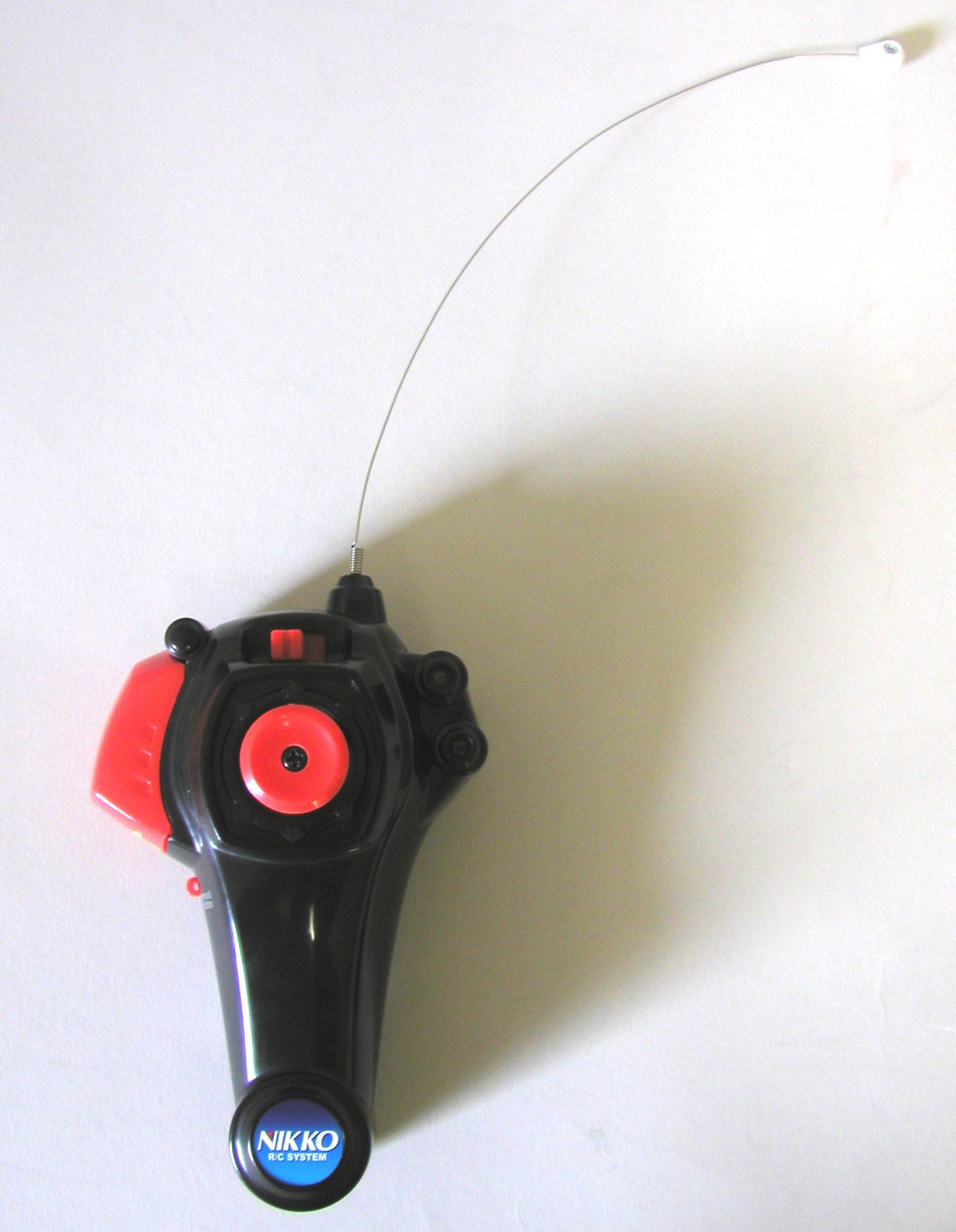
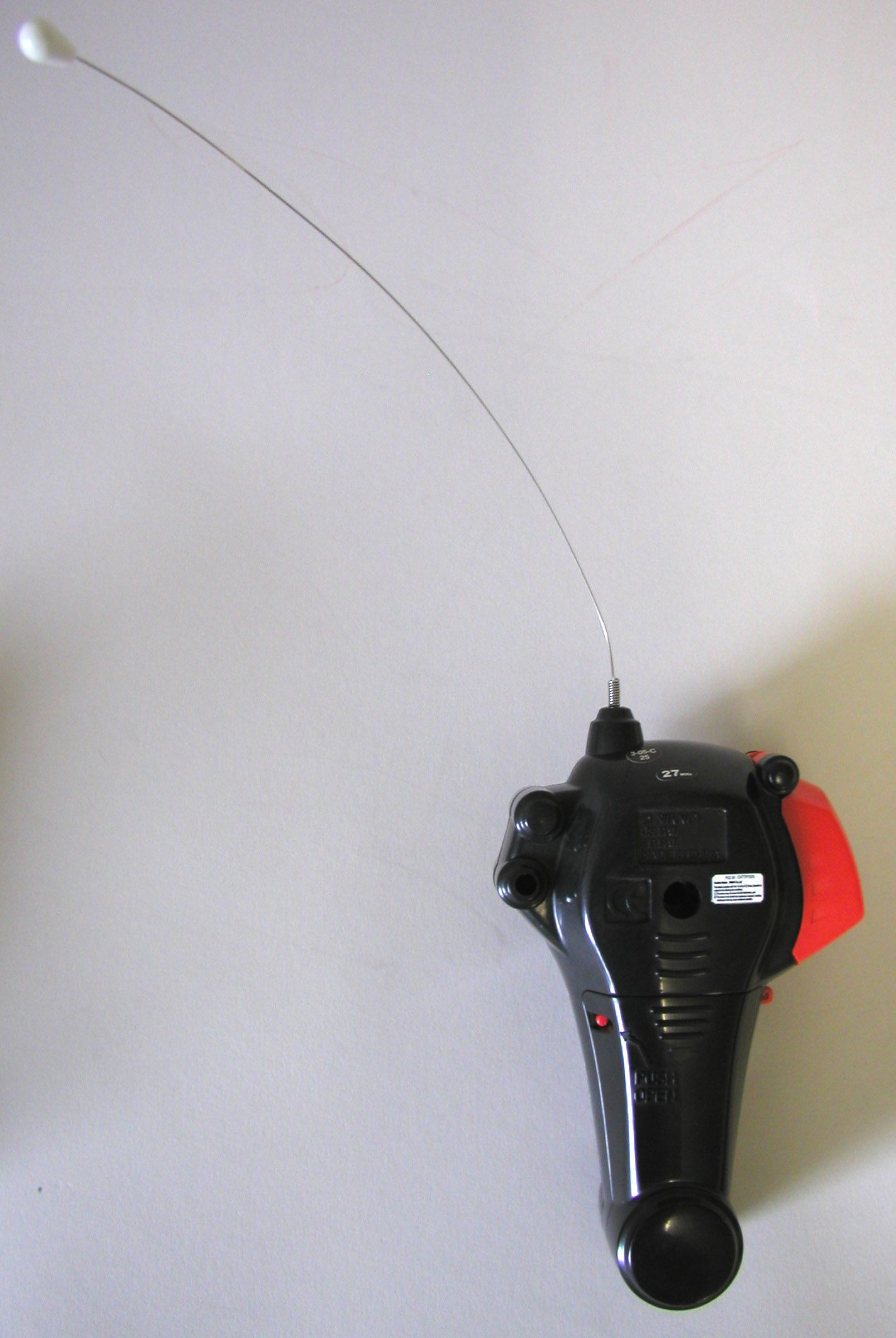
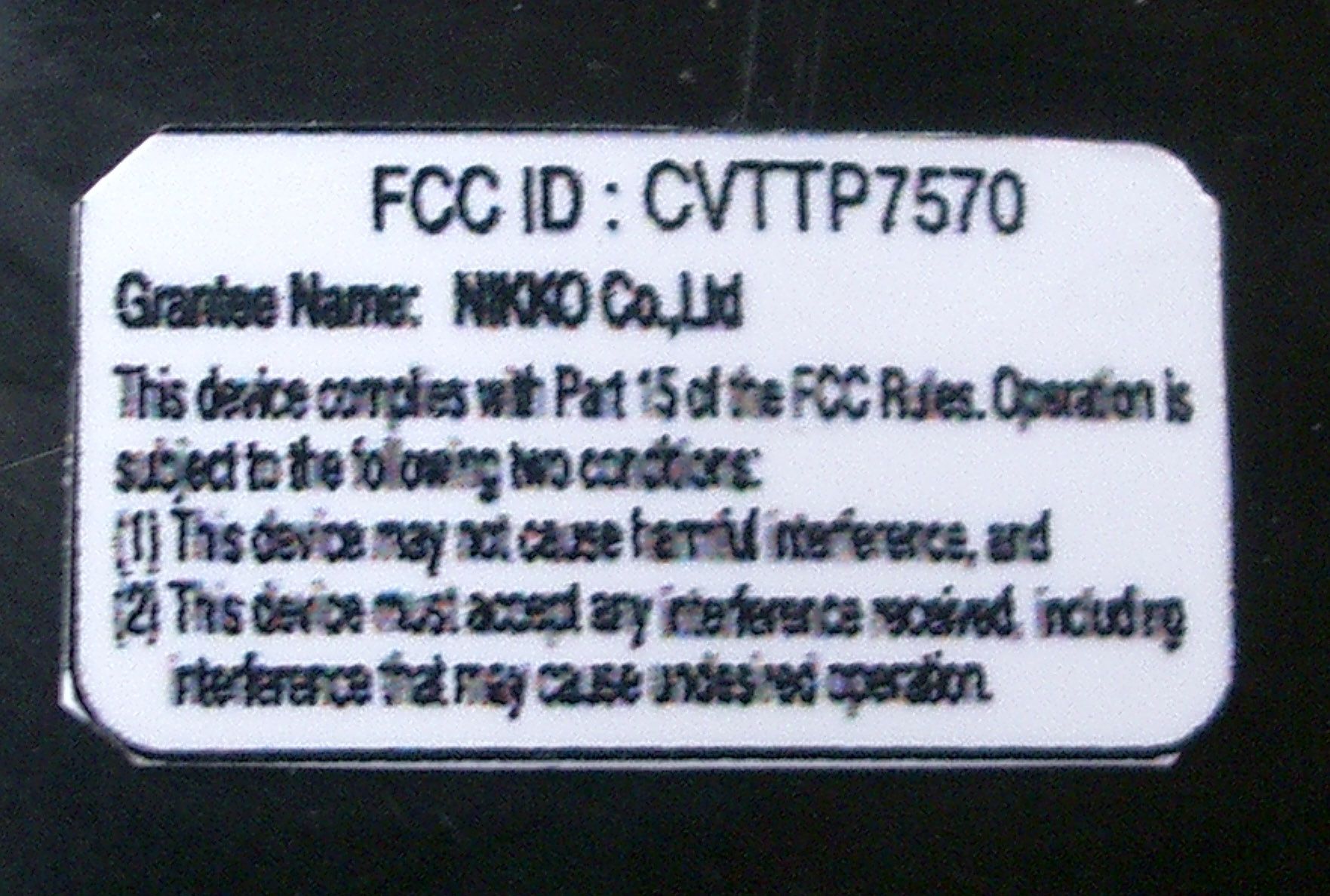
CVTTP7570Remote Control Toy Transmitter
Nikko Co Ltd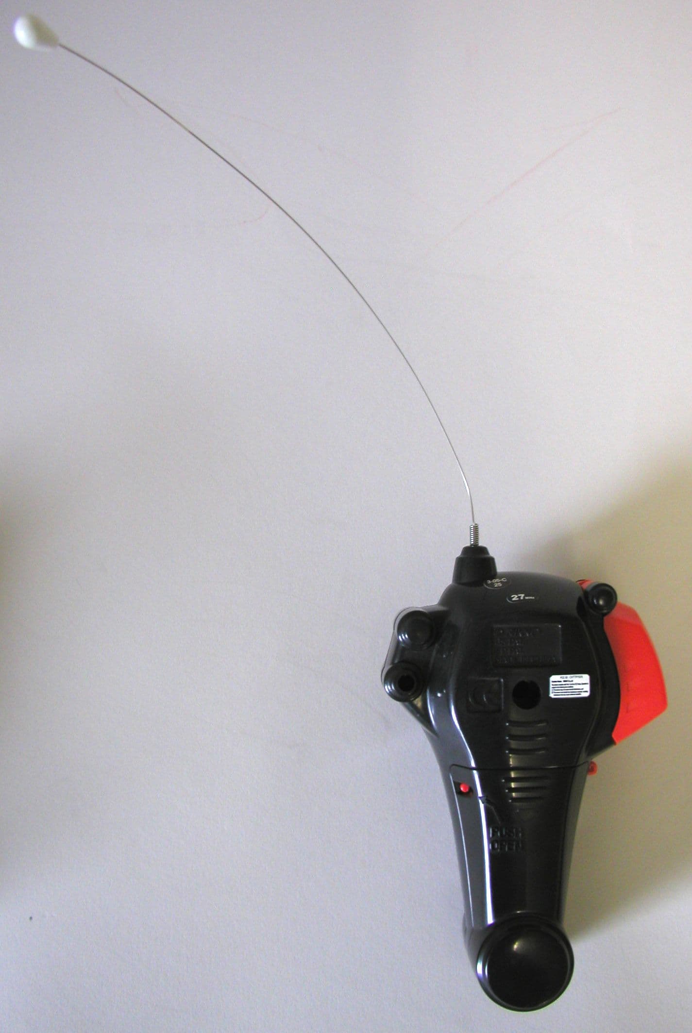
Click to zoom
Application Details
- Equipment Class
- DXX - Part 15 Low Power Communication Device Transmitter
- Date of Grant
- Aug 12, 2003
- Application Purpose
- Original Equipment
- Date of Application
- Aug 12, 2003
- Equipment Note
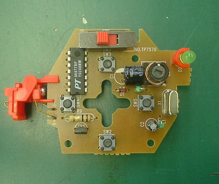
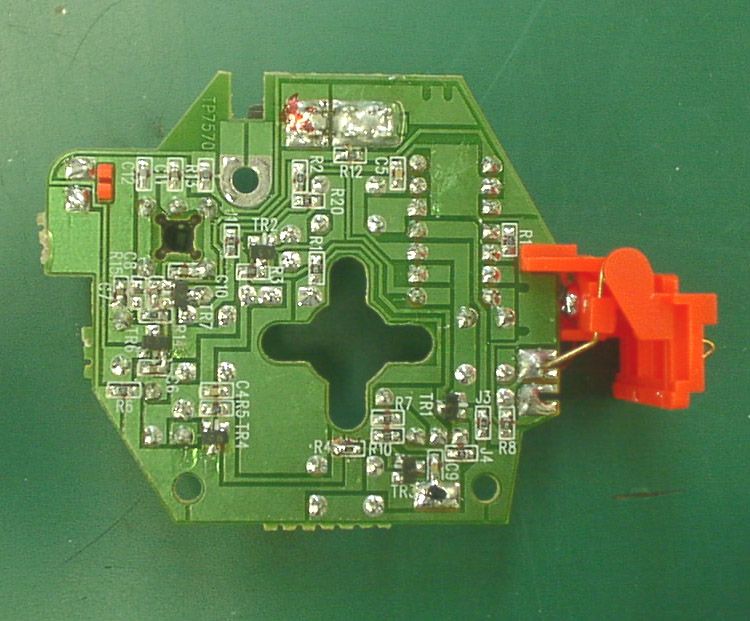
- Remote Control Toy Transmitter
- Frequency Range
- 26.99500000 - 27.25500000
- Company
- Nikko Co Ltd
- Country
- Japan
Documents & Files
Document Text
Text extracted from the exhibit documents filed with the FCC. Open a document above to read the original.
Users Manual
Nikko MicroRadioControl System”iTruck” RDC-700600 -2- -3--4- -1- For ages 6 and over Manual of Instructions *Thank you for choosing NIKKO iTruck! *Read this Manual of Instructions care- fully to the end before starting to play. *Don’t throw away the box or this manual, but keep them for future use. *The actual product may differ slightly from the illustrations. Features *The controller (transmitter) has a built-in battery recharger. Attach iTruck to the controller for quick recharging and lasting power. *A large volume, high-power nickel metal hydride battery is built into the chassis. *The controller has only 1 control stick. Forward-backward running, left-right turns, and stopping are all possible with single-hand operations. Battery requirements: Size "AA" "UM3" "R6" alkaline batteries x 2 (No other type of battery should be used) Battery Characteristics and Recharging Tips When playing for the first time after purchase, or after a long interval, the battery power may be weak. Even after recharging, the running time can be relatively short. The battery will gradually regain power after 2 or 3 repetitions of usage and recharging. Also, if you keep the power switch turned ON for a long time, the battery power will be discharged. Make sure to turn OFF the power switch immediately after use. Names of the Parts iTruck Receiver antenna Top side Steering alignment lever Power switch Bottom side Recharging terminal (iTruck side) Charger cover CONTROLLER Center marker holder Recharging terminal (control- ler side) release button Power switch Recharging monitor lamp (green LED) Control stick Top side Transmitter antenna Battery lid Bottom side safety hook removal button How to Install the Controller Batteries Use a ballpoint pen to open the battery lid. Install 2 alkaline batteries Battery installation: *Install the batteries in the controller. (This product operates only with size "AA" "UM3" "R6"alkaline batteries. If you use man- ganese or other types of batteries, the nickel metal hydride battery built into the vehicle may not be recharged fully. Be sure to use ONLY alkaline dry cell batteries.) Make sure that the power switch of the controller is turned OFF. Use a ballpoint pen, pencil or sharp tools to push the release button of the battery lid. While pressing the button, slide the lid a little bit as shown in the diagram. *Slide out the lid with your hand and detach. *Be careful so that the pencil lead will not be broken. Install 2 size "AA" "UM3" "R6" alkaline batteries, making sure that the (+) and (-) ends are positioned properly. Attach the battery lid again. Slide the lid back into position until the release button clicks. (Lift up the rear end of the battery lid slightly to fit the lid into the groove as shown in the diagram. Then, keep the lid flat and slide into the groove.) There is a safety hook on the controller to prevent ve- hicle from falling off while recharging. When vehicle is fully recharged, the green LED lamp will turn off. When this has been confirmed, keep pressing the recharg- ing release button on the side of the controller, and pull vehicle toward you to detach it from the controller. removal button iTruck power switch is turned OFF Controller power switch is turned ON Open the charger cover Fit the claw of the con- troller into the hollow pit of the chassis. Slide iTruck forward until you hear a click. The set-up is completed! Check to see that iTruck does not fall off. The green LED lamp lights up. The ordinary recharging time is about 2 minutes. (The LED lamp will turn off when recharging is completed.) Contents of the Kit iTruck x 1Controller x 1 Manual of Instructions x 1 close the lid. If the product is used in low temperatures, the battery duration can be shorter than normal. This is a characteristic feature of the battery and is not a defect. The situation can be improved by recharging the battery immediately before playing. The battery power tends to be weakened as time elapses. When you have finished recharging, de- tach iTruck from the controller and replace the recharger cover. Fit into the groove. To remove the bot- tom battery more easily, press the mi- nus (-) end with your finger and pull out the plus (+) end. Procedures for Recharging iTruck (Remove dust or filth from the charger Recharging terminal.) Follow the correct procedures when recharging. When the battery starts to run out of power, the LED lamp will grow dim. 12 3 4 12 34 56 7 8 ATTENTION PARENTS It is recommended that this toy and all accessories be periodically ex- amined for potential hazards and that any potentially hazardous parts be repaired or replaced. IT IS A VIOLATION OF THE FCC REGULA- TIONS TO REMODEL OR ALTER THIS DE- VICE IN ANY WAY WITHOUT PERMISSION, ANYONE WHO VIOLATES THE REGULA- TIONS WILL LOSE THE RIGHT TO OPERATE THE DEVICE. Repair and Parts Department Monday to Friday 8:30AM-5:30PM Central Time Repair:(800)736-4556 Parts:(800)776-4556 Fax:(972)578-7059 e-mail:[email protected] -6- -7--8- P_No.R700600NC030530 If there is anything wrong with the vehicle movements, check the following: What’s wrong? Cause 1 The power switch on vehicle is in the OFF position. 2 The vehicle is too far away from the controller. 3 The (+) and (-) poles of the batter- ies of the controller are positioned in the wrong direction. 4 The metal tab touching the con- troller battery is rusted. 5 The metal recharging terminals of the controller or boat may be rusted. 6 Either the controller batteries or vehicle battery lack power. 7 There is another radio control ve- hicle using the same band being operated nearby. 8 The antenna of the controller or vehicle is bent. Check and see 1 Turn ON the power switch on ve- hicle . 2 Shorten the distance between the controller and vehicle . 3 Install the batteries in the right di- rection. 4 Use sandpaper to remove the rust. 5 Use sandpaper to remove the rust. 6 Either change the controller batter- ies with new ones or recharge ve- hicle as necessary. 7 …
Text truncated - open the document above for the full version.
Operational Description
TP7570 CIRCUIT EXPLANATION FCC ID:CVTTP7570 1)When SW2,3,4 or SW5 is pushed,a control signal is outputted from the IC. 2)TR6 forms the Radio Frequency oscillator. 4)The Amplitude Modulation of the Radio Frequency is performed in TR7 by placing the waves on Audio Frequency. 5)AM. waves are output into the collector of TR7,passed through the filter, and is transmitted from the Antenna. 6)TR1,2,3,4, and 5 form the rx battery charger circuit. 7) TR1 and 2 form the timer circuit,when the battery of RX is connected, a timer starts, and TR3, 4 and 5 turn it on, and it starts the charge. NIKKO CO.,LTD
Test Report
JAPAN QUALITY ASSURANCE ORGANIZATION 21-25, KINUTA 1-CHOME, SETAGAYA-KU, TOKYO 157-8573 JAPAN PHONE (03) 3416-0111, FAX (03) 3416-9691 JQA APPLICATION NO.: 400-30209 Issue Date : July 1, 2003 Page 1 of 35 EMI TEST REPORT JQA APPLICATION NO. : 400-30209 Model No. : TP7570 Type of Equipment : Radio Controlled Toy (Transmitter) Regulations Applied : CFR 47 FCC Rules and Regulations Part 15 FCC ID : CVTTP7570 Applicant : NIKKO CO., LTD. Address : 1-7-14, Mizumoto, Katsushika-ku, Tokyo 125-0032, Japan Manufacturer : NIKKO TEC INTERNATIONAL LTD. Address : Room 182, Houston Center, 63 Mody Road, Tsimshatsui, Kowloon, Hong Kong Received date of EUT : June 13, 2003 Final Judgment : Passed Test results in this report are obtained in use of equipment that is traceable to National Institute of Advanced Industrial Science and Technology (AIST) of Japan and Communication Research Laboratory (CRL) of Japan. The test results only respond to the tested sample. This report should not be reproduced except in full, without the written approval of JQA EMC Engineering Dept. Testing Div. C O P Y JQA Application No. :400-30209 FCC ID : CVTTP7570 Model No. :TP7570 Issue Date :July 1, 2003 Standard :CFR 47 FCC Rules Part 15 Page 2 of 35 JAPAN QUALITY ASSURANCE ORGANIZATION TABLE OF CONTENTS Page 1 Documentation 1.1 Test Regulation 3 1.2 General Information 3 1.3 Test Condition 4 – 8 1.4 EUT Modifications / Deviation from Standard 9 1.5 Test results 10 1.6 Summary 11 1.7 Test Configuration / Operation of EUT 12 1.8 EUT Arrangement(Drawing) 13 1.9 Preliminary Test and Test-setup (Drawings) 14 – 19 1.10 EUT Arrangement (Photographs) 20 – 21 2 Test Data 2.1 AC Power Line Conducted Emission N/A 2.2 Radiated Emission (Electric Field) 23 – 24 2.3 Frequency Stability N/A 2.4 Occupied Bandwidth 25 – 31 3 Appendix Test instruments List 32 – 35 C O P Y JQA Application No. :400-30209 FCC ID : CVTTP7570 Model No. :TP7570 Issue Date :July 1, 2003 Standard :CFR 47 FCC Rules Part 15 Page 3 of 35 JAPAN QUALITY ASSURANCE ORGANIZATION 1 DOCUMENTATION 1.1 TEST REGULATION FCC Rules and Regulations Part 15 Subpart A and B (June 23, 1989) Superregenerative Receiver Test procedure : AC power line conducted emission, radiated emission and antenna conducted power tests were performed according to the procedures in ANSI C63.4-1992. 1.2 GENERAL INFORMATION 1.2.1 Test facility : 1) Test Facility located at EMC Engineering Dept. Testing Div. : - No.2 and 3 Anechoic Chambers( 3 meters Site ). - Shielded Enclosure. Expiration date of FCC test facility filing : May 27, 2005 2) EMC Engineering Dept. Testing Div. is recognized under the National Voluntary Laboratory accreditation Program for satisfactory compliance established in title 15, Part 285 Code of Federal Regulations. NVLAP Lab Code : 200189-0 (Effective through : June 30, 2004) 1.2.2 Description of the Equipment Under Test (EUT) : 1) Type of Equipment : Radio Controlled Toy 2) Product Type : Pre-Production 3) Category : Low Power Communication Device Transmitter 4) EUT Authorization : Certification 5) FCC ID : CVTTP7570 6) Trade Name : NIKKO 7) Model No. : TP7570 8) Operating Frequency Range : 27.145 MHz 9) Highest Frequency Used in the EUT : 27.145 MHz 10) Serial No. : None 11) Date of Manufacture : June 2003 12) Power Rating : 3.0 VDC(Battery) 13) EUT Grounding : None 1.2.3 Definitions for symbols used in this test report : x - indicates that the listed condition, standard or equipment is applicable for this report. - indicates that the listed condition, standard or equipment is not applicable for this report. C O P Y JQA Application No. :400-30209 FCC ID : CVTTP7570 Model No. :TP7570 Issue Date :July 1, 2003 Standard :CFR 47 FCC Rules Part 15 Page 4 of 35 JAPAN QUALITY ASSURANCE ORGANIZATION 1.3 TEST CONDITION 1.3.1 The measurement of the AC Power Line Conducted Emission - was performed in the following test site. x - was not applicable. Test location : Safety & EMC Center EMC Engineering Dept. Testing Div. 21-25, Kinuta 1-chome, Setagaya-ku, Tokyo 157-8573, Japan - Shielded Enclosure - Anechoic Chamber No. 2 (portable Type) Used test instruments : Type Number of test instruments (Refer to Appendix) Test Receiver Spectrum Analyzer Cable AMN(for EUT) AMN(for Peripheral) Termination C O P Y JQA Application No. :400-30209 FCC ID : CVTTP7570 Model No. :TP7570 Issue Date :July 1, 2003 Standard :CFR 47 FCC Rules Part 15 Page 5 of 35 JAPAN QUALITY ASSURANCE ORGANIZATION 1.3.2 The measurement of the Radiated Emission(9 kHz – 30 MHz) x - was performed in the following test site. - was not applicable. Test location : Safety & EMC Center EMC Engineering Dept. Testing Div. 21-25, Kinuta 1-chome, Setagaya-ku, Tokyo 157-8573, Japan - Anechoic Chamber No. 2 (3 meters) x - Anechoic Chamber No. 3 (3 meters) Validation of Site Attenuation : 1) Last Confirmed Date : N/A 2) Interval : N/A Used test instruments : Type Number of test instruments (Refer to Appendix) Test Receiver TR07 Antenna AN01 Cable CA06 C O P Y JQA Application No. :400-30209 FCC ID : CVTTP7570 Model No. :TP7570 Issue Date :July 1, 2003 Standard :CFR 47 FCC Rules Part 15 Page 6 of 35 JAPAN QUALITY ASSURANCE ORGANIZATION 1.3.3 The measurement of the Radiated Emission(30 MHz – 1000 MHz) x - was performed in the following test site. - was not applicable. Test location : Safety & EMC Center EMC Engineering Dept. Testing Div. 21-25, Kinuta 1-chome, Setagaya-ku, Tokyo 157-8573, Japan - Anechoic Chamber No. 2 (3 meters) x - Anechoic Chamber No. 3 (3 meters) Validation of Site Attenuation : 1) Last Confirmed Date :March, 2003 2) Interval :1 year Used test instruments : Type Number of test instruments (Refer to Appendix) Test Receiver TR06 Antenna AN07, AN09 Cable CA02 RF Amplifier N/A C O P Y JQA Application No. :400-30209 FCC ID : CVTTP7570 Model No. :TP7570 Issue Date :July 1, 2003 Standard :CFR 47 FCC Rules Part 15 Page 7 of 35 JAPAN QUALITY ASSURANCE ORGANIZATION 1.3.4 The measurement of the Radiated Emission(Above 1000 MHz) - was performed…
Text truncated - open the document above for the full version.
Test Setup Photos
JQA Application No. :400-30209 FCC ID : CVTTP7570 Model No. :TP7570 Issue Date :July 1, 2003 Standard :CFR 47 FCC Rules Part 15 Page 20 of 35 JAPAN QUALITY ASSURANCE ORGANIZATION 1.10 TEST ARRANGEMENT (PHOTOGRAPHS) PHOTOGRAPHS OF EUT CONFIGURATION FOR RADIATED EMISSIONS MEASUREMENT Photograph present configuration with maximum emission C O P Y JQA Application No. :400-30209 FCC ID : CVTTP7570 Model No. :TP7570 Issue Date :July 1, 2003 Standard :CFR 47 FCC Rules Part 15 Page 21 of 35 JAPAN QUALITY ASSURANCE ORGANIZATION C O P Y
Contact Information
Applicant
Minori Oohira
81-3 3609-0900Fax: 81 3-3609-1033
Test Firm
Japan Quality Assurance Org.Tetsuo Kato
Technical Specifications
| # | Rule Parts | Frequency Range | Power Output |
|---|---|---|---|
| 1 | 15C | 26.995 MHz - 27.255 MHz | - |
Other Applications from Nikko Co Ltd
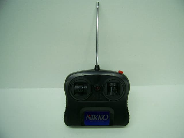
CVTTA7752
Mar 12, 2008Radio Controlled Toy
Equipment Class
DXX - Part 15 Low Power Communication Device Transmitter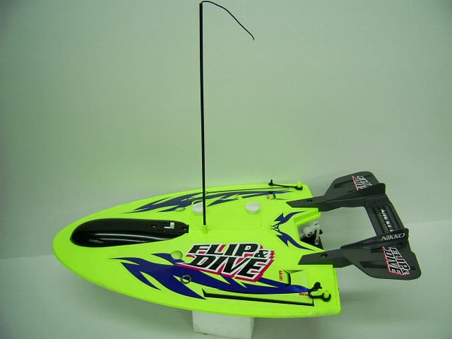
CVTRA4040H
Mar 12, 2008Radio Controlled Toy
Equipment Class
CYY - Communications Receiver used w/Pt 15 Transmitter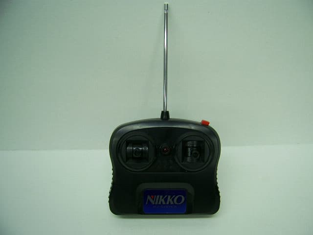
CVTTP7752H
Mar 12, 2008Radio Controlled Toy
Equipment Class
DXX - Part 15 Low Power Communication Device Transmitter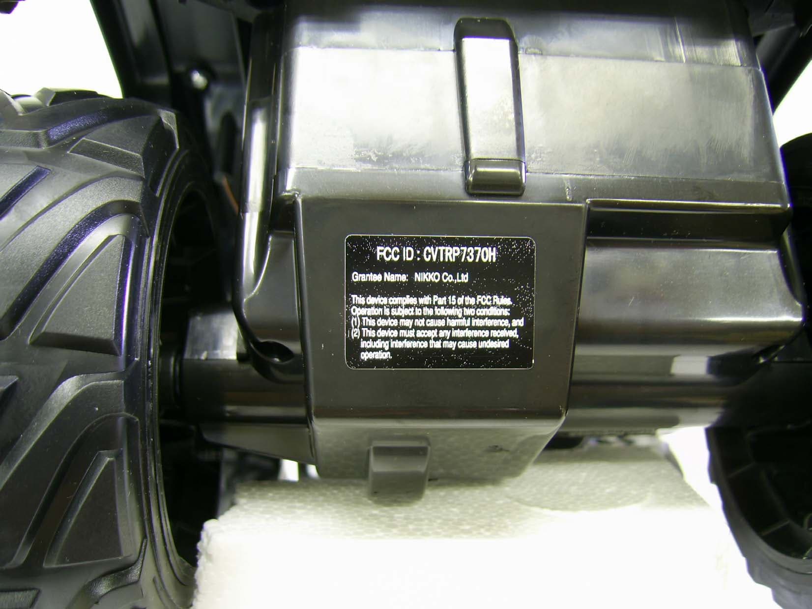
CVTRP7370H
Jul 24, 2007Radio Controlled Toy Receiver
Equipment Class
CYY - Communications Receiver used w/Pt 15 Transmitter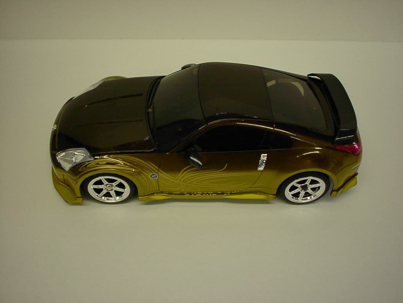
CVTRP7340H
Jan 28, 2007Radio Controlled Toy
Equipment Class
CRR - Superregenerative Receiver