CVTTP7745Radio Controlled Toy(Transmitter)
Nikko Co Ltd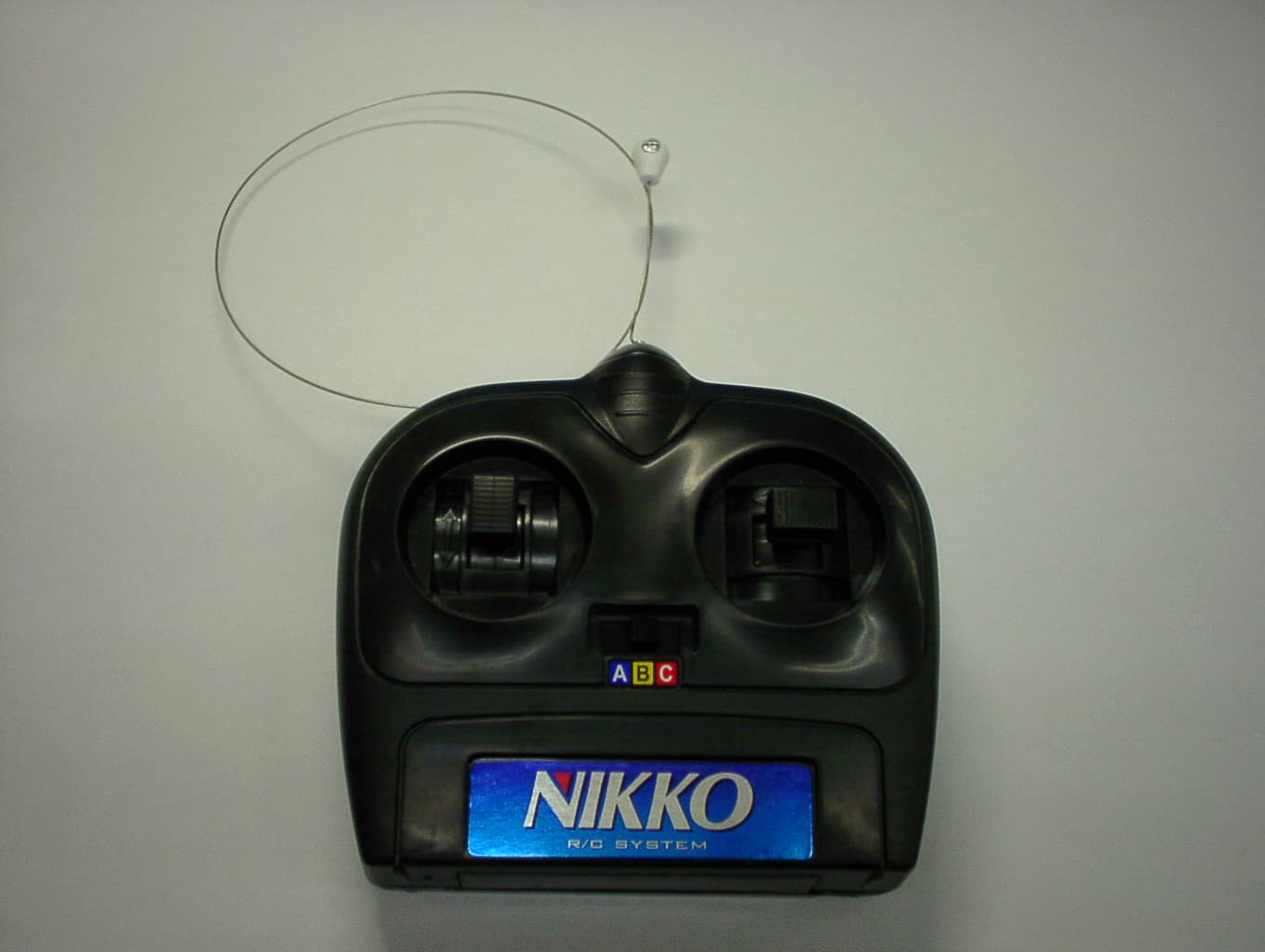
Click to zoom
Application Details
- Equipment Class
- DXX - Part 15 Low Power Communication Device Transmitter
- Date of Grant
- Jan 28, 2007
- Application Purpose
- Original Equipment
- Date of Application
- Jan 28, 2007
- Equipment Note
- Radio Controlled Toy(Transmitter)
- Frequency Range
- 26.99500000 - 27.19500000
- Company
- Nikko Co Ltd
- Country
- Japan
Documents & Files
Document Text
Text extracted from the exhibit documents filed with the FCC. Open a document above to read the original.
Users Manual
.. - 1 - - 3 -- 5 -- 4 - Repair and Parts Department Monday to Friday 8:30AM-5:30PM Central Time Repair :(800)736-4556 Parts :(800)776-4556 Fax :(972)578-7059 e-mail :[email protected] 1/16 STREET CAR * Antes de comenzar a jugar, lea este Manual con mucho cuidado. * ¡Advertencia! Úselo bajo la supervisión directa de un adulto. * Conserve la caja y el manual para referencias futuras. * El producto real puede diferir ligeramente de las ilustraciones. ATENCIÓN PADRES Se recomienda que este juguete y todos sus accesorios sean examinados periódicamente para tratar de encontrar peligros potenciales provocados por piezas que necesiten ser reparadas o cambiadas. * Lisez attentivement ce manuel jusqu’à la fin avant de commencer à jouer. * Avertissement! A utiliser sous la supervision directe d’un adulte. * Conserver la boîte d’affichage et le manuel pour toute référence ultérieure. * La moto contenue dans I'emballage peut ne pas correspondre exactement aux illustrations. * Read this Manual carefully to the end before beginning to play. * Warning! Use under the direct supervision of an adult. * Keep the display box and the manual for future reference. * Actual product may vary from illustration of this manual. ATTENTION PARENTS It is recommended that this toy and all accessories be periodically examined for potential hazards and that any potential hazardous parts be repaired or replaced. • Full function - Runs forward backward, turns left & right, stop. - 3 band selector switch. BATTERY REQUIREMENTS (Not included) Vehicle: 4 x AA alkaline(1.5V) Transmitter:1 x 9V(006P)battery PARENTS ATTENTION Il est recommandé de vérifier périodiquement l’absence de risque potentiel sur ce jouet et tous les accessoires, et de réparer ou remplacer les pièces potentiellement dangereuses. PILES (non fournies) Véhicule: 4 piles format R6 (UM-3) alcalines (1,5 V) Emetteur: 1 pile 6F22(9V) Département Réparation et pièces Lundi au vendredi, de 8h30 à 17h30, heure centrale Réparations : (800) 736-4556 Pièces : (800) 776-4556 Fax : (972) 578-7059 Courrier électronique : [email protected] Departamento de Reparación y Repuestos Lunes a viernes 8:30 AM – 5:30 PM Hora Central Reparaciones : (800) 736-4556 Repuestos : (800) 776-4556 Fax : (972) 578-7059 e-mail : [email protected] • Funciones completas - Avanza, retrocede, gira hacia la izquierda y derecha, se detiene. - 3 interruptor del selector de la banda. English Owner's Manual Manuel de I'utilisateurManual del Propietario FrançaisEspañol PILAS USADAS (No incluidas) Vehículo: 4 x AA (R6) alcalinas (1,5 V) Transmisor: 1 pila 6F22 de 9 V (006P) • Toutes les fonctions - Marche avant, arrière, virage à droite et à gauche, et arrêt. - Sélecteur 3 bandes. FEATURES CARACTERISTIQUES CARACTERÍSTICAS 1/16 scale Echelle 1/16 Modelo a escala 1/16 © NIKKO 1 BATTERY INSTALLATION 9V(006P) TRANSMITTER VEHICLE TO OPEN THE BATTERY COMPARTMENT LID 4 AA alkaline(1.5V) or Ni-Cd(1.2V)batteries. Steering alignment lever 3 MAJOR CAUSES OF VEHICLE MALFUNCTION * WEAK BATTERIES * INCORRECT BATTERY INSTALLATION * INTERFERENCE Battery lid Make sure that the power switch of the vehicle is OFF. Let the battery compartment lid slide forward a little with a pressure on to the latch. Then, the battery compartment lid can be pulled and open. CAUTION WHEN USING BATTERIES Install batteries making sure that the + and - poles of the batteries are positioned accurately. Make sure vehicle's on-off switch is turned OFF when installing batteries. Avoid combined use of new dry batterries and old ones. Avoid combined use of Ni-Cd batteries and dry batteries. Avoid combined use of charged Ni-Cd batteries and discharged Ni-Cd batteries. Remove all the batteries from the vehicle and the trans - mitter after playing. 2 1 3 English 2 3 3 ANTI-POWER LOSS TRANSMITTER (To prevent unnecessary power loss) The transmitter power is automatically turned ON when the speed control stick is operated either to the forward running or reverse running positions, When the stick is returned to the neutral position, the trans - mitter power is turned OFF. When the trans - mitter power is turned OFF, the vehicle can be jammed by other transceiver radio waves and start to move abnormally. NOTE: You can control the vehicle at a longer distance by holding the transmitter higher with the antenna straight up. When the vehicle slows down or starts moving erratically, replace all the vehicle's batteries with fresh or fully charged ones. TO ADJUST STEERING ALIGNMENT Adjust the steering alignment lever on the underside of the vehicle when the vehicle doesn't run straight forward. Steering alignment lever Check to see that the batteries have been INSTALLED in the COR - RECT position. * STOP IMPORTANT: When speed control stick is in NEUTRAL, Steering Wheel WILL NOT produce any steering action. ON/OFF switch ON OFF ←→ 1 Please follow the above sequence of operation. * Band selector switch on transmitter. Band selector switch on vehicle chassis. Ensure that band selector switch on transmitter and vehicle are set to the same letter - A, B or C. 2 HOW TO OPERATE Turn ON the vehicle. Operate the vehicle with transmitter. Turn OFF the vehicle after operating. Remove all the batteries both from the vehicle and the transmitter. 2 3 4 5 English TRANSMITTER Speed control stick FORWARD NEUTRAL REVERSE Antenna Steering control stick LEFT/STRAIGHT/RIGHT English VEHICLE ON/OFF switch ON OFF ←→ ONON THE FCC WANTS YOU KNOW This device complies with part 15 of the FCC Rules, Operation is subject to the following two conditions: (1) This device may not cause harmful interference. (2) This device must accept any interference received,including interference that may cause undesired operation. Your R/C car might cause TV or radio interference even when it is operating properly. To determine whether your R/C car is causing the interference, turn off your R/C car. If the interference goes away,your R/C car is causing the interference. Try to eliminate the inter…
Text truncated - open the document above for the full version.
Operational Description
PCB:NO.TP7745 CIRCUIT EXPLANATION FCC ID :CVTTP7745 1) The power circuit status to operate when SW1,2,3 or SW4 are turn ON. 2) TR1 forms the Radio Frequency oscillator. 3) The Amplitude Modulation of the Radio Frequency is performed in TR2 by placing the waves on Audio Frequency. 4) AM. waves are output into the collector of TR2,passed through the filter, and is transmitted from the Antenna. 5)TR3 forms auto cut off power on timer. NIKKO CO.,LTD
Test Report
JAPAN QUALITY ASSURANCE ORGANIZATION 21-25, KINUTA 1-CHOME, SETAGAYA-KU, TOKYO 157-8573 JAPAN PHONE +81-3-3416-0111, FAX +81-3-3416-9691 JQA File No. : 400-60605 Issue Date : January 15, 2007 Page 1 of 34 EMI TEST REPORT JQA File No. : 400-60605 Model No. : TP7745 Type of Equipment : Radio Controlled Toy (Transmitter) Regulations Applied : CFR 47 FCC Rules and Regulations Part 15 FCC ID : CVTTP7745 Applicant : NIKKO CO., LTD. Address : 1-7-14, Mizumoto, Katsushika-ku, Tokyo 125-0032, Japan Manufacturer : NIKKO TEC INTERNATIONAL LTD Address : Rm. 601-603, Houston Center, 63, Mody Road, Tsimshatsui East, Kowloon, Hong Kong Received date of EUT : December 14, 2006 Test Result : Passed Test results in this report are obtained in use of equipment that is traceable to National Institute of Advanced Industrial Science and Technology (AIST) of Japan and National Institute of Information and Communications Technology(NICT) of Japan. The test results only respond to the tested sample. This report should not be reproduced except in full, without the written approval of JQA EMC Engineering Dept. Testing Div. This report must not be used by the client to claim product endorsement by NVLAP or NIST any agency of the U.S. Government. NVLAP Lab Code : 200189-0 JQA File No. :400-60605 FCC ID :CVTTP7745 Model No. :TP7745 Issue Date :January 15, 2007 Standard :CFR 47 FCC Rules Part 15 Page 2 of 34 TABLE OF CONTENTS Page 1 Documentation 1.1 Test Regulation 3 1.2 General Information 3 1.3 Test Condition 4 – 8 1.4 EUT Modifications / Deviation from Standard 9 1.5 Test results 10 1.6 Summary 11 1.7 Test Configuration / Operation of EUT 12 1.8 EUT Arrangement(Drawing) 13 1.9 Preliminary Test and Test-setup (Drawings) 14 – 19 1.10 EUT Arrangement (Photographs) 20 – 21 2 Test Data 2.1 AC Power Line Conducted Emission N/A 2.2 Radiated Emission (Electric Field) 22 – 23 2.3 Frequency Stability N/A 2.4 Occupied Bandwidth 24 – 30 3 Appendix Test instruments List 31 – 34 JQA File No. :400-60605 FCC ID :CVTTP7745 Model No. :TP7745 Issue Date :January 15, 2007 Standard :CFR 47 FCC Rules Part 15 Page 3 of 34 1 DOCUMENTATION 1.1 TEST REGULATION FCC Rules and Regulations Part 15 Subpart A and C Intentional Radiators Test procedure : AC power line conducted emission, radiated emission, frequency stability and occupied bandwidth tests were performed according to the procedures in ANSI C63.4-2003. 1.2 GENERAL INFORMATION 1.2.1 Test facility : 1) Test Facility located at EMC Engineering Dept. Testing Div. : - No.2 and 3 Anechoic Chambers( 3 meters Site ). - Shielded Enclosure. 2) EMC Engineering Dept. Testing Div. is accredited under the National Voluntary Laboratory accreditation Program for satisfactory compliance established in title 15, Part 285 Code of Federal Regulations. NVLAP Lab Code : 200189-0 1.2.2 Description of the Equipment Under Test (EUT) : 1) Type of Equipment : Radio Controlled Toy (Transmitter) 2) Product Type : Production 3) Category : Low Power Communication Device Transmitter 4) EUT Authorization : Certification 5) FCC ID : CVTTP7745 6) Trade Name : NIKKO 7) Model No. : TP7745 8) Operating Frequency Range : 27.145 MHz 9) Highest Frequency Used in the EUT : 27.145 MHz 10) Serial No. : None 11) Date of Manufacture : None 12) Power Rating : DC 9.0V(Size 9V Battery x 1) 13) EUT Grounding : None 1.2.3 Definitions for symbols used in this test report : x - indicates that the listed condition, standard or equipment is applicable for this report. - indicates that the listed condition, standard or equipment is not applicable for this report. JQA File No. :400-60605 FCC ID :CVTTP7745 Model No. :TP7745 Issue Date :January 15, 2007 Standard :CFR 47 FCC Rules Part 15 Page 4 of 34 1.3 TEST CONDITION 1.3.1 The measurement of the AC Power Line Conducted Emission - was performed in the following test site. x - was not applicable. Test location : Safety & EMC Center EMC Engineering Dept. Testing Div. 21-25, Kinuta 1-chome, Setagaya-ku, Tokyo 157-8573, Japan - Shielded Enclosure - Anechoic Chamber No. A (portable Type) Used test instruments : Type Number of test instruments (Refer to Appendix) Test Receiver N/A Spectrum Analyzer N/A Cable N/A AMN(for EUT) N/A AMN(for Peripheral) N/A Termination N/A JQA File No. :400-60605 FCC ID :CVTTP7745 Model No. :TP7745 Issue Date :January 15, 2007 Standard :CFR 47 FCC Rules Part 15 Page 5 of 34 1.3.2 The measurement of the Radiated Emission(9 kHz – 30 MHz) x - was performed in the following test site. - was not applicable. Test location : Safety & EMC Center EMC Engineering Dept. Testing Div. 21-25, Kinuta 1-chome, Setagaya-ku, Tokyo 157-8573, Japan x - Anechoic Chamber No. A (3 meters) - Anechoic Chamber No. B (3 meters) Validation of Site Attenuation : 1) Last Confirmed Date : N/A 2) Interval : N/A Used test instruments : Type Number of test instruments (Refer to Appendix) Test Receiver 13 Antenna 21 Cable 43 JQA File No. :400-60605 FCC ID :CVTTP7745 Model No. :TP7745 Issue Date :January 15, 2007 Standard :CFR 47 FCC Rules Part 15 Page 6 of 34 1.3.3 The measurement of the Radiated Emission(30 MHz – 1000 MHz) x - was performed in the following test site. - was not applicable. Test location : Safety & EMC Center EMC Engineering Dept. Testing Div. 21-25, Kinuta 1-chome, Setagaya-ku, Tokyo 157-8573, Japan x - Anechoic Chamber No. A (3 meters) - Anechoic Chamber No. B (3 meters) Validation of Site Attenuation : 1) Last Confirmed Date :March, 2006 2) Interval :1 year Used test instruments : Type Number of test instruments (Refer to Appendix) Test Receiver 11 Antenna 167, 168 Cable 38 RF Amplifier N/A JQA File No. :400-60605 FCC ID :CVTTP7745 Model No. :TP7745 Issue Date :January 15, 2007 Standard :CFR 47 FCC Rules Part 15 Page 7 of 34 1.3.4 The measurement of the Radiated Emission(Above 1000 MHz) - was performed in the following test site. x - was not applicable. Test location : Safety & EMC Center EMC Engineering Dept. Testing Div. 21-25, Kinuta 1-chome, Setagaya-ku, Tokyo 157-8573, Japan -…
Text truncated - open the document above for the full version.
Test Setup Photos
JQA File No. :400-60605 FCC ID :CVTTP7745 Model No. :TP7745 Issue Date :January 15, 2007 Standard :CFR 47 FCC Rules Part 15 Page 20 of 34 1.10 TEST ARRANGEMENT (PHOTOGRAPHS) PHOTOGRAPHS OF EUT CONFIGURATION FOR RADIATED EMISSIONS MEASUREMENT Photograph present configuration with maximum emission JQA File No. :400-60605 FCC ID :CVTTP7745 Model No. :TP7745 Issue Date :January 15, 2007 Standard :CFR 47 FCC Rules Part 15 Page 21 of 34 PHOTOGRAPHS OF EUT CONFIGURATION FOR RADIATED EMISSIONS MEASUREMENT Photograph present configuration with maximum emission
Contact Information
Applicant
Minori Oohira
81-3 3609-0900Fax: 81 3-3609-1033
Test Firm
Japan Qlty. Assur. Org. Safety & EMC CtrHideki Kajiwara
Technical Specifications
| # | Rule Parts | Frequency Range | Power Output |
|---|---|---|---|
| 1 | 15C | 26.995 MHz - 27.195 MHz | - |
Other Applications from Nikko Co Ltd
CVTTA7752
Mar 12, 2008Radio Controlled Toy
Equipment Class
DXX - Part 15 Low Power Communication Device Transmitter
CVTRA4040H
Mar 12, 2008Radio Controlled Toy
Equipment Class
CYY - Communications Receiver used w/Pt 15 Transmitter
CVTTP7752H
Mar 12, 2008Radio Controlled Toy
Equipment Class
DXX - Part 15 Low Power Communication Device Transmitter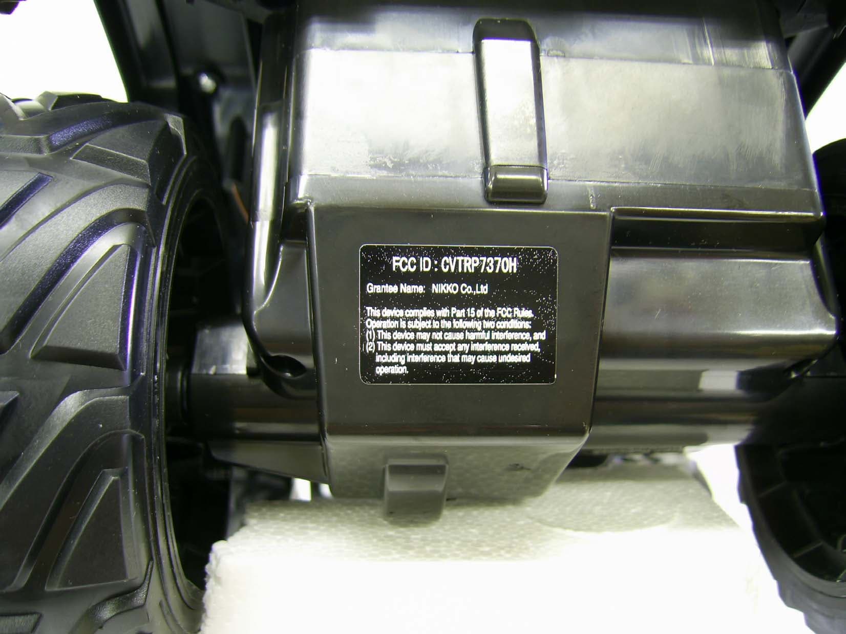
CVTRP7370H
Jul 24, 2007Radio Controlled Toy Receiver
Equipment Class
CYY - Communications Receiver used w/Pt 15 Transmitter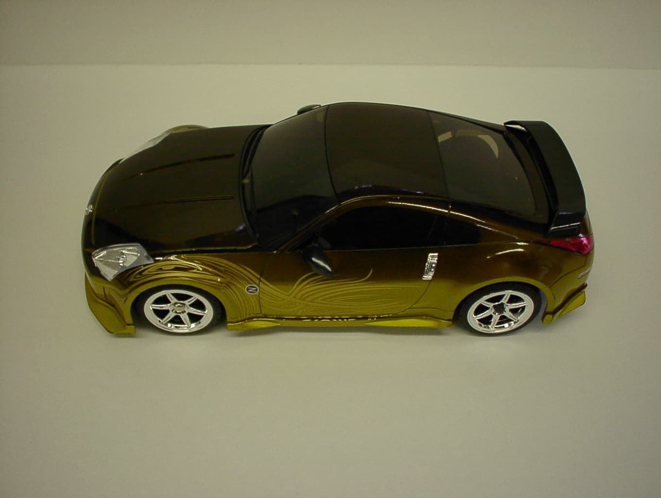
CVTRP7340H
Jan 28, 2007Radio Controlled Toy
Equipment Class
CRR - Superregenerative Receiver