CVTTP7810Remote Controlled Toy Transmitter
Nikko Co Ltd
Click to zoom
Application Details
- Equipment Class
- DXX - Part 15 Low Power Communication Device Transmitter
- Date of Grant
- Apr 29, 2002
- Application Purpose
- Original Equipment
- Date of Application
- Apr 29, 2002
- Equipment Note
- Remote Controlled Toy Transmitter
- Frequency Range
- 26.99500000 - 27.25500000
- Company
- Nikko Co Ltd
- Country
- Japan
Documents & Files
Document Text
Text extracted from the exhibit documents filed with the FCC. Open a document above to read the original.
Users Manual
1 SEA TIGERSEA TIGER SEA TIGERSEA TIGER SEA TIGER RDC-300080 NIKKO RADIO CONTROL MANUAL OF INSTRUCTIONSMANUAL OF INSTRUCTIONS MANUAL OF INSTRUCTIONSMANUAL OF INSTRUCTIONS MANUAL OF INSTRUCTIONS Read this manual carefully to the end before playing. Keep this manual for future reference. Features of SUB-168Features of SUB-168 Features of SUB-168Features of SUB-168 Features of SUB-168 *2-channel, 9 functions: submerge, surface, left/right turn, spin turn, stop, etc. *By adjusting the angle of the left/right screws, SUB-168 can make a quick dive or quick sur- face. *The 2-motor system can make the left/right screws turn in opposite directions and thereby enable the submarine to spin turn. *By adjusting the left/right screws at different angles, SUB-168 can make a tornado dive or rolling dive. *If you stop operating, or if the radio waves fail to reach the submarine, the safety system will automatically bring the vessel to the surface. {When the submarine is submersed underwater{When the submarine is submersed underwater {When the submarine is submersed underwater{When the submarine is submersed underwater {When the submarine is submersed underwater , the radio waves can be transmitted to a, the radio waves can be transmitted to a , the radio waves can be transmitted to a, the radio waves can be transmitted to a , the radio waves can be transmitted to a distance of about 5m. Keep the submarine within a range of 5m. from the transmitterdistance of about 5m. Keep the submarine within a range of 5m. from the transmitter distance of about 5m. Keep the submarine within a range of 5m. from the transmitterdistance of about 5m. Keep the submarine within a range of 5m. from the transmitter distance of about 5m. Keep the submarine within a range of 5m. from the transmitter .}.} .}.} .} *The hull is water-tight and can submerge to a depth of about 60cm. *The transmitter is water-resistant, so there is no need to worry if it gets wet. Battery RequirementsBattery Requirements Battery RequirementsBattery Requirements Battery Requirements [Transmitter]: 6F22(9V) dry cell battery x 1 [Submarine]: Size-AA alkaline batteries x 3 (Use ONLY AA-size alkaline batteries) Contents of the KitContents of the Kit Contents of the KitContents of the Kit Contents of the Kit Submarine x 1 Transmitter x 1 Manual of Instructions X 1 Diving weight x 16 Horizontal trim weight x 7 Antenna tube x 1 2 Names of the PartsNames of the Parts Names of the PartsNames of the Parts Names of the Parts [Submarine] Power switch Diving weight case Horizontal trim weight cast Battery compartment hatch Right screw Left screw The periscope is theThe periscope is the The periscope is theThe periscope is the The periscope is the power switch. Pushpower switch. Push power switch. Pushpower switch. Push power switch. Push down/ pull up to turndown/ pull up to turn down/ pull up to turndown/ pull up to turn down/ pull up to turn ON/OFFON/OFF ON/OFFON/OFF ON/OFF .. .. . [Transmitter] Left screw forward drive button Left screw reverse drive button Right screw forward drive button Right screw forward drive button Water-proof antenna Battery compartment lid (Reverse side) How to attach the antenna tube [When playing in a large pool] Pass the antenna wire through the antenna tube. If the antenna tube does not fit well into the antenna tube holder, hold the root of the antenna wire with one hand, and pull the wire gently with the other hand. This will make it easier for the antenna tube to fit into the holder. [When playing in the bathtub or other small places] When playing in a relatively small tank of water like the bathtub, or example, fit the antenna wire into the holder on the tail fin. Antenna tube Antenna wire Antenna holder Tail fin CAUTION Do not pull the antenna wire too strongly. Antenna tube holder 3 Battery InstallationBattery Installation Battery InstallationBattery Installation Battery Installation How to Install Batteries Slide the stopper forward and remove the hatch. [Submarine] * Avoid mixed use of old and new batteries, or mixed use of different types of batteries. * Make sure that the power switch of the subma- rine is turned OFF when exchanging batteries. Hull Battery box Battery compart- ment hatch Terminal side Terminal (metal part) (1) Make sure that the power switch is turned OFF. (2) As shown in the diagram, slide the stopper forward and remove the battery compartment hatch by turning in the clockwise direction (looking at the submarine from the rear). (3) Remove the battery box from the hull. Install 3 size-AA alkaline batteries. Make sure that The + and - poles are positioned prop- erly. (4) Put the battery box back into the hull from the terminal side first, with the terminal (metal part) on top. (5) Replace the battery compartment hatch. Turn the hatch in the counterclockwise direction. * Fit the hatch in firmly and screw in tightly so that water will not seep into the battery compart- ment. (Be careful so that the battery box is replaced in the right direction. The box is designed so that it will not fit in the wrong direction. Don't jam the box in by force.) [Transmitter] (1) Use a + screwdriver to remove the screw attaching the battery lid. (2) Slide the lid to the side and remove. (3) Install the battery, making sure that the + and - poles are positioned properly. (4) Replace the battery compartment lid and screw in. (The screwdriver is not included in the kit.) 6F22(9V) dry cell battery (You cannot obtain complete water-tightness unless the screws are firmly attached.) 4 Adjustment of the TAdjustment of the T Adjustment of the TAdjustment of the T Adjustment of the T rim and Wrim and W rim and Wrim and W rim and W eighteight eighteight eight * Make sure that the specified batteries are installed properly, and that the battery compartment hatch is screwed in and locked firmly before putting the submarine into the water. <Adjustment of the waterline><Adjustment of the waterline> <Adjustment of the waterline><Adjustment of…
Text truncated - open the document above for the full version.
Operational Description
NO:TP7810 CIRCUIT EXPLANATION FCC ID :CVTTP7810 1)The power circuit status to operate when SW1 or SW2,SW3,SW4 are turn ON. 2)TR3 forms the Radio Frequency oscillator. 4)The Amplitude Modulation of the Radio Frequency is performed in TR4 by placi ng the waves on Au dio Frequency. 5)AM. waves are output into the collector of TR4,passed through the filter, and is transmitted from the Antenna. 6)Tr1 and TR2 forms the Reset circuits. 7)When Tr1 and Tr2 active,IC is reset. NIKKO CO.,LTD R&D Dept.CHIEF Y.MAEDA
Test Report
JAPAN QUALITY ASSURANCE ORGANIZATION 21-25, KINUTA 1-CHOME, SETAGAYA-KU, TOKYO 157-8573 JAPAN PHONE (03) 3416-0111, TELEX 242-2531 JQA J FAX (03) 3416-9691 JQA APPLICATION NO.: 400-10844 Issue Date : April 5, 2002 Page 1 of 29 EMI TEST REPORT JQA APPLICATION NO. : 400-10844 Model No. : TP7810 Type of Equipment : Radio Controlled Toy (Transmitter) Regulations Applied : CFR 47 FCC Rules and Regulations Part 15 FCC ID : CVTTP7810 Applicant : NIKKO CO., LTD. Address : 1-7-14, Mizumoto, Katsushika-ku, Tokyo 125-0032, Japan Manufacture : NIKKO TEC INTERNATIONAL LTD. Address : Room 812, Houston Center, 63 Mody Road, Tsimshatsui, Kowloon, Hong Kong Received date of EUT : March 28, 2002 Final Judgment : Passed Test results in this report are obtained in use of equipment that is traceable to National Institute of Advanced Industrial Science and Technology (AIST) of Japan and Communication Research Laboratory (CRL) of Japan. The test results only respond to the tested sample. This report should not be reproduced except in full, without the written approval of JQA EMC Engineering Dept. Testing Div. C O P Y JQA Application No. :400-10844 FCC ID :CVTTP7810 Model No. :TP7810 Issue Date :April 5, 2002 Standard :CFR 47 FCC Rules Part 15 Page 2 of 29 JAPAN QUALITY ASSURANCE ORGANIZATION TABLE OF CONTENTS Page 1 Documentation 1.1 Test Regulation 3 1.2 General Information 3 1.3 Test Condition 4 – 8 1.4 EUT Modifications / Deviation from Standard 9 1.5 Test results 10 1.6 Summary 11 1.7 Test Configuration / Operation of EUT 12 1.8 EUT Arrangement(Drawing) 13 1.9 Preliminary Test and Test-setup (Drawings) 14 – 19 1.10 EUT Arrangement (Photographs) 20 - 21 2 Test Data 2.1 AC Power Line Conducted Emission 0.45 MHz – 30 MHz N/A 2.2 Radiated Emission (Electric Field) 22 – 23 2.3 Frequency Stability N/A 2.4 Occupied Bandwidth 24 – 29 C O P Y JQA Application No. :400-10844 FCC ID :CVTTP7810 Model No. :TP7810 Issue Date :April 5, 2002 Standard :CFR 47 FCC Rules Part 15 Page 3 of 29 JAPAN QUALITY ASSURANCE ORGANIZATION 1 DOCUMENTATION 1.1 TEST REGULATION FCC Rules and Regulations Part 15 Subpart A and C (June 23, 1989) Intentional Radiators Test procedure : AC power line conducted emission, radiated emission, frequency stability and occupied bandwidth tests were performed according to the procedures in ANSI C63.4-1992. 1.2 GENERAL INFORMATION 1.2.1 Test facility : 1) Test Facility located at EMC Engineering Dept. Testing Div. : - No.2 and 3 Anechoic Chambers( 3 meters Site ). - Shielded Enclosure. Expiration date of FCC test facility filing : June 04, 2002 2) EMC Engineering Dept. Testing Div. is recognized under the National Voluntary Laboratory accreditation Program for satisfactory compliance established in title 15, Part 285 Code of Federal Regulations. NVLAP Lab Code : 200189-0 (Effective through : June 30, 2002) 1.2.2 Description of the Equipment Under Test (EUT) : 1) Type of Equipment : Radio Controlled Toy (Transmitter) 2) Product Type : Production 3) Category : Low Power Communication Device Transmitter 4) EUT Authorization : Certification 5) FCC ID : CVTTP7810 6) Trade Name : NIKKO 7) Model No. : TP7810 8) Operating Frequency Range : 27.145 MHz 9) Highest Frequency Used in the EUT : 27.145 MHz 10) Serial No. : None 11) Date of Manufacture : March 2002 12) Power Rating : DC 9.0V(Battery) 13) EUT Grounding : None 1.2.3 Definitions for symbols used in this test report : x - indicates that the listed condition, standard or equipment is applicable for this report. - indicates that the listed condition, standard or equipment is not applicable for this report. C O P Y JQA Application No. :400-10844 FCC ID :CVTTP7810 Model No. :TP7810 Issue Date :April 5, 2002 Standard :CFR 47 FCC Rules Part 15 Page 4 of 29 JAPAN QUALITY ASSURANCE ORGANIZATION 1.3 TEST CONDITION 1.3.1 The measurement of the AC Power Line Conducted Emission - was performed in the following test site. x - was not applicable. Test location : Safety & EMC Center EMC Engineering Dept. Testing Div. 21-25, Kinuta 1-chome, Setagaya-ku, Tokyo 157-8573, Japan - Shielded Enclosure - Anechoic Chamber No. 2 (portable Type) Used test instruments : Type Model No. Manufacturer Serial No. Last Cal. Interval - Test Receiver ESH-2 Rohde & Schwarz 880370/016 June 2001 1 Year - Test Receiver ESH-3 Rohde & Schwarz 881460/030 May 2001 1 Year - Test Receiver ESHS10 Rohde & Schwarz 835871/004 Aug. 2001 1 Year - LISN(for Peripheral) KNW-407 Kyoritsu Electrical 8-833-6 Apr. 2001 1 Year - LISN(for EUT) KNW-407 Kyoritsu Electrical 8-855-2 Apr. 2001 1 Year - LISN KNW-407 Kyoritsu Electrical 8-757-1 Apr. 2001 1 Year - RF Cable 3D-2W Fujikura 155-21-006E0 Apr. 2001 1 Year - RF Cable 3D-2W Fujikura 155-21-007E0 Apr. 2001 1 Year - 50ohm Termination - SUHNER 154-06-501E0 Jan. 2002 1 Year - 50ohm Termination - SUHNER 154-06-502E0 Jan. 2002 1 Year C O P Y JQA Application No. :400-10844 FCC ID :CVTTP7810 Model No. :TP7810 Issue Date :April 5, 2002 Standard :CFR 47 FCC Rules Part 15 Page 5 of 29 JAPAN QUALITY ASSURANCE ORGANIZATION 1.3.2 The measurement of the Radiated Emission(9 kHz – 30 MHz) x - was performed in the following test site. - was not applicable. Test location : Safety & EMC Center EMC Engineering Dept. Testing Div. 21-25, Kinuta 1-chome, Setagaya-ku, Tokyo 157-8573, Japan x - Anechoic Chamber No. 2 (3 meters) - Anechoic Chamber No. 3 (3 meters) Validation of Site Attenuation : 1) Last Confirmed Date : N/A 2) Interval : N/A Used test instruments : Type Model No. Manufacturer Serial No. Last Cal. Interval - Test Receiver ESH-2 Rohde & Schwarz 880370/016 June 2001 1 Year - Test Receiver ESH-3 Rohde & Schwarz 881460/030 May 2001 1 Year - Test Receiver ESHS10 Rohde & Schwarz 835871/004 Aug 2001 1 Year x - Test Receiver ESVS10 Rohde & Schwarz 826148/002 May 2001 1 Year x - Antenna HFH2-Z2 Rohde & Schwarz 881058/62 Nov 2001 1 Year x - RF Cable RG-213/U F & G 155-21-010E0 Apr. 2001 1 Year C O P Y JQA Application No. :400-10844 FCC ID :CVTTP7810 Model No. :TP7810 Issue Date :April…
Text truncated - open the document above for the full version.
Contact Information
Applicant
Minori Oohira
81-3 3609-0900Fax: 81 3-3609-1033
Test Firm
Japan Quality Assurance Org.Tetsuo Kato
Technical Specifications
| # | Rule Parts | Frequency Range | Power Output |
|---|---|---|---|
| 1 | 15C | 26.995 MHz - 27.255 MHz | - |
Other Applications from Nikko Co Ltd
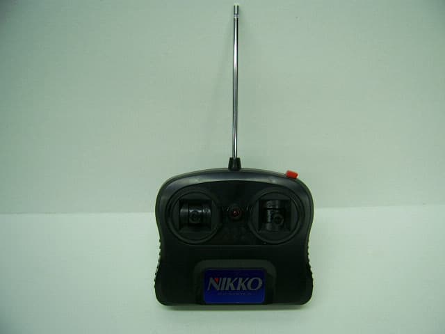
CVTTA7752
Mar 12, 2008Radio Controlled Toy
Equipment Class
DXX - Part 15 Low Power Communication Device Transmitter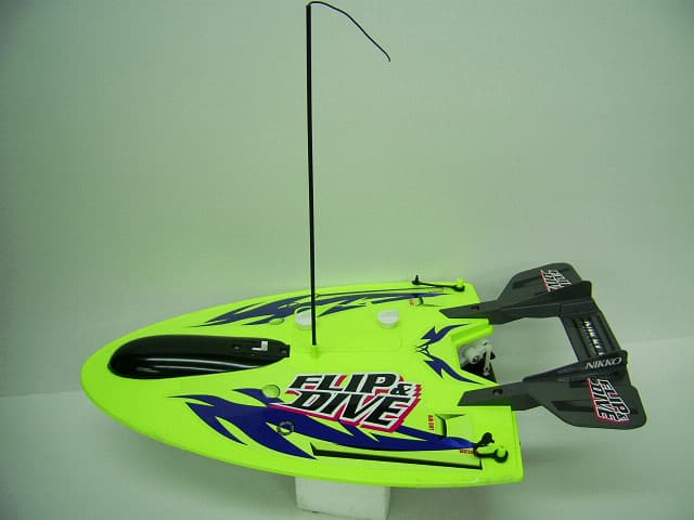
CVTRA4040H
Mar 12, 2008Radio Controlled Toy
Equipment Class
CYY - Communications Receiver used w/Pt 15 Transmitter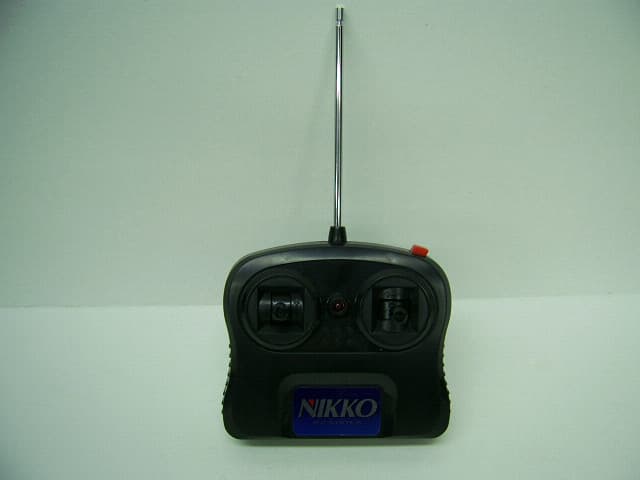
CVTTP7752H
Mar 12, 2008Radio Controlled Toy
Equipment Class
DXX - Part 15 Low Power Communication Device Transmitter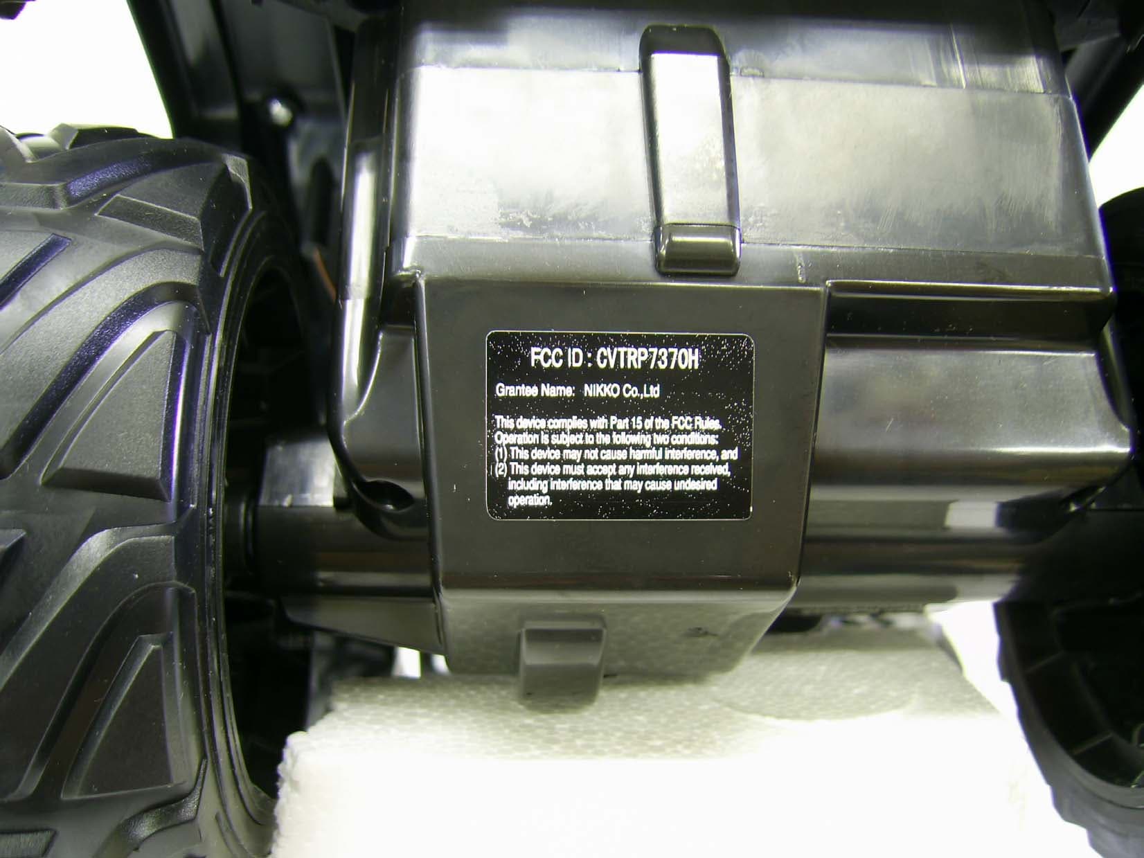
CVTRP7370H
Jul 24, 2007Radio Controlled Toy Receiver
Equipment Class
CYY - Communications Receiver used w/Pt 15 Transmitter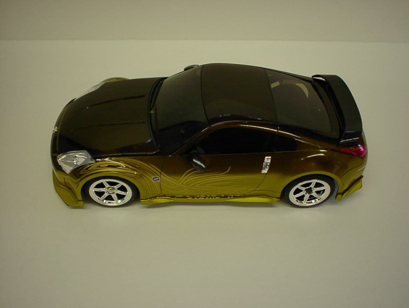
CVTRP7340H
Jan 28, 2007Radio Controlled Toy
Equipment Class
CRR - Superregenerative Receiver