DCO-BN-3S-33Remote Controller BN-3S-33V (BN-3S-33RC)
Alpha Arsenal LLC
Click to zoom
Application Details
- Equipment Class
- DSC - Part 15 Security/Remote Control Transmitter
- Date of Grant
- Oct 06, 2014
- Application Purpose
- Original Equipment
- Date of Application
- Oct 06, 2014
- Equipment Note
- Remote Controller BN-3S-33V (BN-3S-33RC)
- Frequency Range
- 434.50000000 - 434.50000000
- Company
- Alpha Arsenal LLC
- Country
- United States
Documents & Files
Document Text
Text extracted from the exhibit documents filed with the FCC. Open a document above to read the original.
Users Manual
6 WARRANTY INFORMATION The internet site: www.alpha-safe.com contains the full version of the Motion Detector operating manual. Together with you, we have just executed basic set up. If you desire to review set up more thoroughly, then access and familiarize yourself with the contents of this resource. Also, we draw your attention to the possibility of setting up the Motion Detector by using special programs available on this site. These programs allow for convenient and easy Motion Detector set up using your computer, smart phone or tablet running OS Android or iMac. You may contact us with any questions at: 1.718.440.3281, or via the internet at: www.alpha-safe.c om Warranty period is one year from date of purchase. During the Warranty period manufacturer will repair, exchange, adjust, or replace at its discretion, any defective product. This warranty does not cover damage resulting from any unauthorized attempt to repair or from any use not in accordance with the instruction manual. Warranty does not cover physical damage of any kind whatsoever or cover damage caused by any attempt to tamper with or disassemble the product. Warranty does not cover the battery. Warranty period commences on the day first purchased from manufacturer or an authorized reseller as evidenced by a purchase receipt. Without a valid receipt of purchase, manufacturer is relieved of its obligation to provide warranty service. Date of sale: Seller name: Seal _____________ ____________________________ ________ MOTION DETECTOR ALARM SYSTEM EXPRESS - GSM VERSION 2 Quick Start Guide Watch the instructional set up video at: http://www.alpha-safe.com/prod/video2.php 1 PREPARATION The operational principle of the Motion Detector is similar to that of an automatic door sensor located in a store. As you approach the door; it opens. The Motion Detector, likewise, senses human movement and sends an SMS message containing the text "Alarm" and places a call to your mobile phone. An optional wireless Siren can be connected to the Motion Detector. Remove the screw from the lower base of the unit and lift off the Motion Detector cover. Do not touch or service the circuit board components contained inside the Motion Detector and/or Siren. These are for access by qualified service technicians only. If you purchased an optional Siren, open it by removing the screw from the lower base of the unit body. Place a slotted screwdriver, exerting slight pressure, alternately, into each slot located to the right and left of the screw. Lift off the Siren cover. Purchase a new SIM card and record the telephone number below: Insert a SIM card into the Motion Detector SIM card holder. The beveled SIM card corner should be located in the upper left corner of the SIM card holder. 2 SET UP You will have only one minute to complete the set up procedure, after which the Motion Detector will turn off. If you were unable to complete all the set up procedure steps, remove the battery from the Motion Detector and the Siren, wait 2 minutes and repeat the set up procedure from the beginning. Re-install the battery into the Motion Detector battery holder observing the correct polarity. Wait for 3 audible sound signals and then call the Motion Detector (the telephone number recorded in the space on page 1) from your telephone. After receiving the call, the Motion Detector will emit an audible sound signal and will then disconnect the incoming call. In order to set up the Siren, remove the protective plastic insert from between the battery and its holder. After an audible sound signal, the LED (Light Emitting Diode) will blink 3 times indicating that the Siren is successfully connected to the Motion Detector. Set up the Remote Controller by briefly pressing button ; Set up will conclude by emitting an audible sound signal. Replace the covers on the Motion Detector and Siren; insert and tighten the screws. In approximately 1 minute you will receive an incoming SMS message containing set up details. Simply confirm that immediately following position 1) your telephone number is registered and visible. The additional sets up details are for advanced users only. 3 INSTALLATION Install the Motion Detector in a location inaccessible by unauthorized persons and with an unobstructed view of the protected zone. The recommended installation height is approximately 2 m/ 6.5 ft. The detection range for human presence is approximately 10 m/ 32 ft within the protected zone. Do not install the Motion Detector near heat sources (fireplaces, stoves, air conditioners, heating radiators) or in any location exposed to strong air flow or direct sunlight. Use the included wall bracket or double sided adhesive tape to mount the Motion Detector on the wall. The wall on which the Motion Detector is mounted should not be exposed to vibration. The presence of objects in the protected zone, such as furniture, screens, plants, etc., might create "blind spots", possibly hindering the detection of human presence. The presence of animals and birds within the protected zone may trigger false alarming. The Siren may be placed in any convenient location, for example, on a bookshelf or hung on a screw. For stable and dependable operation, the distance between the Motion Detector and Siren should not exceed 10-15 m/ 32-48 ft. 4 VERIFICATION x Press button on the Remote Controller, the LED will blink yellow and red, the Siren will beep once and will then emit an audible sound signal. For 1 minute, the Motion Detector will continue to emit audible sound signals. During this span of time, the protected zone must be vacated. Simply exit to an adjacent room. x Wait for an incoming SMS message containing the text "Armed by Remote Controller 1". x Wait for 2-3 minutes and then enter the protected zone. x The Siren will start emitting audible sound and visual light signals. x Wait for an incoming SMS message containing the text "Alarm" and an incoming call from the Motion Detector. x Place a call from yo…
Text truncated - open the document above for the full version.
External Photos
Report No.: 0048-140923-01 Remote Controller Model No.: BN-3S-33V(BN-3S-33RC) FCC ID: DCO-BN-3S-33 —————————————————————————————————————————— —————————————————————————————————————————— Advanced Compliance Lab, 6 Randolph Way, Hillsborough, NJ 08844 Tel: (908) 927-9288 Fax: (908) 927-0728 22 Figure 7.1 Front View Report No.: 0048-140923-01 Remote Controller Model No.: BN-3S-33V(BN-3S-33RC) FCC ID: DCO-BN-3S-33 —————————————————————————————————————————— —————————————————————————————————————————— Advanced Compliance Lab, 6 Randolph Way, Hillsborough, NJ 08844 Tel: (908) 927-9288 Fax: (908) 927-0728 23 Figure 7.2 Rear View
ID Label/Location Info
Report No.: 0048-140923-01 Remote Controller Model No.: BN-3S-33V(BN-3S-33RC) FCC ID: DCO-BN-3S-33 —————————————————————————————————————————— —————————————————————————————————————————— Advanced Compliance Lab, 6 Randolph Way, Hillsborough, NJ 08844 Tel: (908) 927-9288 Fax: (908) 927-0728 8 2. PRODUCT LABELING Figure 2.1 FCC ID Label Figure 2.2 Location of Label on the Side of EUT Figure 2.2 FCC ID Label Location FCC ID: DCO-BN-3S-33 This device complies with part 15 of the FCC Rules. Operating is subject to the following two conditions: (1) This device may not cause harmful interference, and (2) this device must accept any interference received, including interference that may cause undesired operation. Figure 2.1 FCC ID Label FCC Label
Internal Photos
Report No.: 0048-140923-01 Remote Controller Model No.: BN-3S-33V(BN-3S-33RC) FCC ID: DCO-BN-3S-33 —————————————————————————————————————————— —————————————————————————————————————————— Advanced Compliance Lab, 6 Randolph Way, Hillsborough, NJ 08844 Tel: (908) 927-9288 Fax: (908) 927-0728 24 BN-3S-33V BN-3S-33RC Figure 7.3 Cover opened_ Inside View Report No.: 0048-140923-01 Remote Controller Model No.: BN-3S-33V(BN-3S-33RC) FCC ID: DCO-BN-3S-33 —————————————————————————————————————————— —————————————————————————————————————————— Advanced Compliance Lab, 6 Randolph Way, Hillsborough, NJ 08844 Tel: (908) 927-9288 Fax: (908) 927-0728 25 BN-3S-33V BN-3S-33RC Figure 7.4 Component Side Report No.: 0048-140923-01 Remote Controller Model No.: BN-3S-33V(BN-3S-33RC) FCC ID: DCO-BN-3S-33 —————————————————————————————————————————— —————————————————————————————————————————— Advanced Compliance Lab, 6 Randolph Way, Hillsborough, NJ 08844 Tel: (908) 927-9288 Fax: (908) 927-0728 26 BN-3S-33V BN-3S-33RC Figure 7.5 Foil Side
Test Report
ELECTROMAGNETIC EMISSION COMPLIANCE REPORT of Remote Controller MODEL: BN-3S-33V (BN-3S-33RC) FCC ID: DCO-BN-3S-33 September 29, 2014 This report concerns (check one): Original grant x Class II change Equipment type: Low Power Intentional Radiator Deferred grant requested per 47 CF 0.457(d)(1)(ii)? yes no x If yes, defer until: (date) Company agrees to notify the Commission by (date) of the intended date of announcement of the product so that the grant can be issued on that date. Transition Rules Request per 15.37? yes no x If no, assumed Part 15, Subpart B for unintentional radiators - the new 47 CFR [10-1-90 Edition] provision. Report prepared for: ALPHA ARSENAL LLC Report prepared by: Advanced Compliance Lab Report number: 0048-140923-01 The test result in this report IS supported and covered by the NVLAP accreditation 6 Randolph Way Hillsborough, NJ 08844 Tel: (908) 927 9288 Fax: (908) 927 0728 Advanced Compliance Laboratory Report No.: 0048-140923-01 Remote Controller Model No.: BN-3S-33V(BN-3S-33RC) FCC ID: DCO-BN-3S-33 —————————————————————————————————————————— —————————————————————————————————————————— Advanced Compliance Lab, 6 Randolph Way, Hillsborough, NJ 08844 Tel: (908) 927-9288 Fax: (908) 927-0728 2 Table of Contents Report Cover Page ..................................................................................................... 1 Table of Contents ....................................................................................................... 2 Figures ........................................................................................................................ 3 1. GENERAL INFORMATION................................................................................ 4 1.1 Verification of Compliance ...................................................................... 4 1.2 Equipment Modifications ........................................................................ 5 1.3 Product Information ................................................................................ 6 1.4 Test Methodology ..................................................................................... 6 1.5 Test Facility .............................................................................................. 6 1.6 Test Equipment ........................................................................................ 6 1.7 Statement for the Document Use ............................................................. 7 2. PRODUCT LABELING ........................................................................................ 8 3. SYSTEM TEST CONFIGURATION ................................................................... 9 3.1 Justification .............................................................................................. 9 3.2 Special Accessories ................................................................................... 9 3.3 Configuration of Tested System ............................................................... 9 4. SYSTEM SCHEMATICS ..................................................................................... 13 5. CONDUCTED EMISSION DATA ....................................................................... 14 5.1 Test Methods and Conditions .................................................................. 14 5.2 Test Data ................................................................................................... 14 6. RADIATED EMISSION DATA............................................................................ 17 6.1 Field Strength Calculation ....................................................................... 17 6.2 Test Methods and Conditions .................................................................. 17 6.3 Test Data ................................................................................................... 17 6.4 Occupied Bandwidth ................................................................................ 19 7. PHOTOS OF EUT ................................................................................................ 21 Report No.: 0048-140923-01 Remote Controller Model No.: BN-3S-33V(BN-3S-33RC) FCC ID: DCO-BN-3S-33 —————————————————————————————————————————— —————————————————————————————————————————— Advanced Compliance Lab, 6 Randolph Way, Hillsborough, NJ 08844 Tel: (908) 927-9288 Fax: (908) 927-0728 3 Figures Figure 2.1 FCC ID Label ........................................................................................... 8 Figure 2.2 Location of Label on Back of the EUT .................................................... 8 Figure 3.1 Radiated Test Setup, Position 1 ............................................................... 10 Figure 3.2 Radiated Test Setup, Position 2 ............................................................... 10 Figure 3.3 Radiated Test Setup, Position 3 ............................................................... 11 Figure 3.4 Conducted Test Setup, Front................................................................... 12 Figure 3.5 Conducted Test Setup, Rear .................................................................... 12 Figure 4.1 EUT Schematics ....................................................................................... 13 Figure 5.1 Line Conducted ........................................................................................ 15 Figure 5.2 Neutral Conducted .................................................................................. 16 Figure 6.1 Bandwidth Plot ........................................................................................ 19 Figure 6.2 Pulse Train Timing .................................................................................. 20 Figure 7.1 Front View ................................................................................................ 22 Figure 7.2 Rear View ................................................................................................. 23 F…
Text truncated - open the document above for the full version.
Test Setup Photos
Report No.: 0048-140923-01 Remote Controller Model No.: BN-3S-33V(BN-3S-33RC) FCC ID: DCO-BN-3S-33 —————————————————————————————————————————— —————————————————————————————————————————— Advanced Compliance Lab, 6 Randolph Way, Hillsborough, NJ 08844 Tel: (908) 927-9288 Fax: (908) 927-0728 10 Figure 3.1 Radiated Test Setup, position 1-X Figure 3.2 Radiated Test Setup, position 2-Y Report No.: 0048-140923-01 Remote Controller Model No.: BN-3S-33V(BN-3S-33RC) FCC ID: DCO-BN-3S-33 —————————————————————————————————————————— —————————————————————————————————————————— Advanced Compliance Lab, 6 Randolph Way, Hillsborough, NJ 08844 Tel: (908) 927-9288 Fax: (908) 927-0728 11 Figure 3.3 Radiated Test Setup, position 3-Z
Contact Information
Applicant
Sergey Medvedev(General Manager)
Test Firm
Advanced Compliance LaboratoryWei Li
Technical Specifications
| # | Rule Parts | Frequency Range | Power Output |
|---|---|---|---|
| 1 | 15.231 | 434.5 MHz - 434.5 MHz | - |
Other Applications from Alpha Arsenal LLC
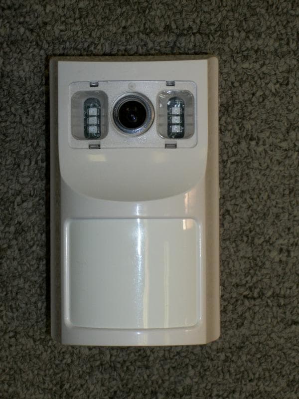
DCO-EXPRESS-E3
Jan 07, 2013GSM Motion Detector Express-E3 GSM unit
Equipment Class
DSR - Part 15 Remote Control/Security Device Transceiver
DCO-EXPRESSGSM2
Aug 27, 2012Express GSM2 GSM Unit EXPRESSGSM2
Equipment Class
DSR - Part 15 Remote Control/Security Device Transceiver
DCO-BN3-433A
Aug 27, 2012Express GSM2 Remote Control BN3-433A
Equipment Class
DSR - Part 15 Remote Control/Security Device Transceiver
DCO-SN1-A
Aug 13, 2012EXPRESSGSM2 SIREN SN1-A
Equipment Class
DSR - Part 15 Remote Control/Security Device Transceiver
DCO-EXPRESSGSM1
May 19, 2012Express GSM 433 Tx/Rx Base Unit ExpressGSM1
Equipment Class
DSR - Part 15 Remote Control/Security Device Transceiver