DE4-4120TChime Transmitter
Thomas & Betts Corporation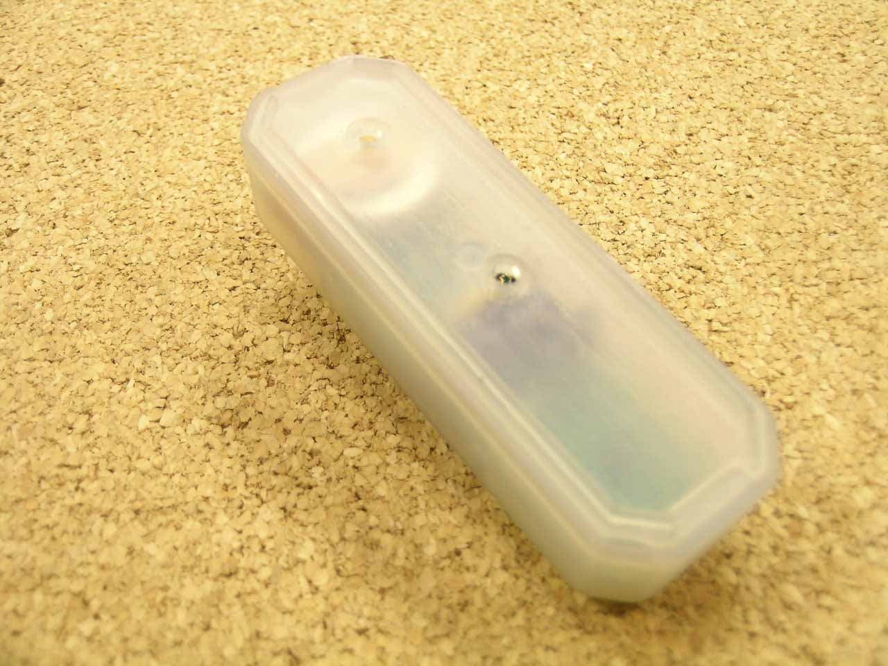
Click to zoom
Application Details
- Equipment Class
- DSC - Part 15 Security/Remote Control Transmitter
- Date of Grant
- Sep 19, 2006
- Application Purpose
- Original Equipment
- Date of Application
- Sep 17, 2006
- Equipment Note
- Chime Transmitter
- Frequency Range
- 315.00000000 - 315.00000000
- Company
- Thomas & Betts Corporation
- Country
- United States
Documents & Files
Document Text
Text extracted from the exhibit documents filed with the FCC. Open a document above to read the original.
Users Manual
INSTRUCTION GUIDE Wireless Chime ButtonsRC3302, RC3303, RC4121 Congratulations on a wise purchase! ENCLOSED YOU WILL FIND: •Chime Button • One 3-volt lithium battery (installed) for RC3302 and RC3303 • Two 3-volt lithium batteries (installed) for RC4121 • Double-sided tape • Screws TOOLS NEEDED: •Small Phillips head screwdriver •Medium flat head screwdriver •Ballpoint pen •Drill, if mounting with screws Note:Your new wireless chime button can only be used to add a button to an existing Carlon Wireless Chime system. It can not be used with any other mechanical or wireless chime system. MOUNTING BACK COVER OF CHIME BUTTON Note: Mounting Chime Button on aluminum siding or metal door frame may reduce range. If button must be mounted on metal, try placing a 1/2’’ piece of wood between the button and the metal. If you want to cover the wire hole from your existing button, save mounting of the new Chime Button until after removing the existing button. 1. Remove cover from back of Button by inserting flat head screwdriver in notch at bottom of transmitter and turn. Lift Chime Button cover away from the back plate. 2. For tape mounting: A) Make sure surfaces are free of dust, oil, and other substances that could affect adhesion. B) Attach double-sided tape to Chime Button back cover. GUÍA DE INSTRUCCIONES Botones de Timbre inalámbrico RC3302, RC3303, RC4121 ¡Lo felicitamos por su compra sabia! SE ADJUNTA: •Botón de timbre •One 3-volt lithium battery (installed) for RC3302 and RC3303 •Dos baterías de litio de 3 voltios (instaladas) for RC4121 •Cinta con pegamento por ambos lados •Tornillos HERRAMIENTAS NECESARIAS: •Pequeño destornillador de cabeza Phillips •Medium flat head screwdriver •Bolígrafo •Taladro, si se monta con tornillos Nota: Su nuevo botón de timbre inalámbrico solamente puede usarse para agregar un botón a un sistema de timbre inalámbrico Carlon existente. No puede usarse con ningún otro sistema de timbre inalámbrico. MONTAJE DE LA CUBIERTA POSTERIOR DEL BOTÓN DE TIMBRE Nota: Instalando el bóton de timbre en uno panel de alumino o montante de puerta en metal puede disminuir el alcance de operación. Si debe instalar el bóton en una pieza de metal, intercale una pieza de madera de 1/2” entre el bóton y el metal. Si desea cubrir el agujero del alambre de su botón existente, guarde el montaje del nuevo botón de timbre hasta después de retirar el botón existente. 1. Remove cover from back of Button by inserting flat head screwdriver in notch at bottom of transmitter and turn. Lift Chime Button cover away from the back plate. 2. Para montaje con cinta: A) Asegúrese de que las superficies estén sin polvo, aceite y otras sustancias que podrían afectar la adhesión. B) Instale la cinta con pegamento por ambos lados en la tapa posterior del botón de timbre. GUIDE D’INSTALLATION Boutons de Carillon sans filRC3302, RC3303, RC4121 Nous vous félicitons de votre choix judicieux ! VOUS TROUVEREZ DANS CET ENSEMBLE : •Un bouton de carillon •One 3-volt lithium battery (installed) for RC3302 and RC3303 •Deux piles au lithium 3 volts (installées) for RC4121 •Un ruban à deux faces •Des vis LES OUTILS NÉCESSAIRES : •Un petit tournevis à pointe cruciforme (Phillips) •Medium flat head screwdriver •Un stylo-bille •Une perceuse, si vous faites un montage avec vis Remarque :Votre nouveau bouton de carillon sans fil ne peut être utilisé que pour ajouter un bouton à un système de carillon sans fil Carlon existant. Il ne peut pas être utilisé avec un autre carillon sans fil ou mécanique. MONTAGE DU DOS DU BOUTON DE CARILLON Remarque : Installer le bouton de carillon sur une planche d’aluminium ou un cadre de porte en métal peut réduire la portée. Si le bouton doit être installé sur du métal, insérez une pièce de bois de 1/2 po entre le bouton et le métal. Si vous voulez couvrir le trou de fil du bouton de sonnette existant, ne montez le nouveau bouton qu’après avoir enlevé le bouton existant. 1. Remove cover from back of Button by inserting flat head screwdriver in notch at bottom of transmitter and turn. Soulevez le devant du bouton pour le séparer du dos. 2. Montage avec le ruban : A) Les surfaces doivent être libres de poussière, d’huile et de toute autre substance qui peut nuire à l’adhésion. B) Posez le ruban à deux faces sur le dos du bouton. C) Making sure that the end with the hook-shaped latch is facing down, press cover firmly to mounting surface. 3. For screw mounting: A) Place Chime Button where desired and mark screw locations. B) Place Chime Button back cover against mounting surface and screw into marked locations using screws enclosed (may require drilling pilot holes on hardwoods). 4. Reattach the Chime Button to the installed back cover. TEST Press Chime Button. Receiver should play tone. CHANGING TONE/MELODY SELECTION To change to a different tone or melody, press once on the small raised Button located on the bottom front of the Button. Receiver will play next selection. To continue changing melody or selection, press down once again and wait for Receiver to confirm change. Note: If you change melodies or tones too rapidly, the Receiver will not play each selection. Only last melody or tone selected will play. Selecting while Receiver is playing will switch system to new setting, but Receiver will only finish playing tone or melody already in progress. FRONT/BACK DOOR CHIME OPERATION With two Chime Buttons, scroll and set a different selection for each door. By remembering which tone/melody is played, you can tell which button is pressed. Chime Buttons may also be used as hand-held pagers. TO REPLACE BATTERIES 1.Remove Chime Button from back cover by inserting flat head screwdriver in notch at bottom of Button and turn. Lift Chime Button cover away from the back plate. 2. Remove old battery(s) by placing a ballpoint pen directly beneath the battery(s). For RC4121, lift the top battery out of the battery compartment. Repeat with second battery. (Do not hit Chime Button to remove batteries - this …
Text truncated - open the document above for the full version.
Cover Letter(s)
Re: Certification for Lamson Transmitter Model(s): 4120T FCC ID: DE4-4120T IC: 2998A-4120T REQUEST FOR CONFIDENTIALITY Pursuant to 47 CRF 0.459, Lamson requests that a part of the subject application be held confidential. This comprises Exhibits (5) Schematics (10) Parts List (Part of Exhibit only) Lamson has spent substantial effort in developing this product and it is one of the first of its kind in industry. Having the subject information easily available to "competition" would negate the advantage they have achieved by developing this product. Not protecting the details of the design will result in financial hardship. If there are any questions regarding this request, please contact me at the above address or call 734-483-4211, fax 734-647-2106 or e-mail [email protected]. Sincerely, Valdis V. Liepa Research Scientist University of Michigan September 12, 2006 Re: Certification for Lamson Transmitter Model(s): 4120T FCC ID: DE4-4120T IC: 2998A-4120T STATEMENT OF MODIFICATIONS There were no modifications made to the DUT by this test laboratory. (Also see Section 3.1 of the attached Test Report). _____________________ Valdis V. Liepa Research Scientist Re: Certification for Lamson Transmitter Model(s): 4120T FCC ID: DE4-4120T IC: 2998A-4120T GENERAL PRODUCT INFORMATION The device, for which certification is pursued, has been designed by: Lamson & Sessions 25701 Science Park Drive Cleveland, Ohio 44122 Mark Roesch [email protected] Tel: 216-766-6762 Fax: 216-831-8016 It will be manufactured by: Lamson & Sessions 25701 Science Park Drive Cleveland, Ohio 44122 Mark Roesch [email protected] Tel: 216-766-6762 Fax: 216-831-8016 Canadian Contact: Lamson & Sessions Don Tully 1439 Nichol's Cove Road Bobcaygeon, Ontario KOM 1A0 Canada Phone: 705-738-3187 Fax: 7-5-738-1351 [email protected] Re: Certification for Lamson Transmitter Model(s): 4120T FCC ID: DE4-4120T IC: 2998A-4120T POWER OF ATTORNEY A letter granting Valdis V. Liepa the Power of Attorney is on file and can be provided when so requested.
Cover Letter(s)
September 12, 2006 American Telecommunications Certification Body, Inc. 6731 Whittier Avenue Suite C110 McLean, VA 22101 RE: Certification Application FCC ID: DE4-4120T IC: 2998A-4120T Model(s): 4120T Please find enclosed application materials for certification of Lamson 4120T Transmitter. Note: 1) portions of this submittal are filed Confidential 2) a list of the modifications made is provided in Attestations. If there are any questions regarding the application or testing performed, please contact me at the above address or call 734-483-4211, fax 734-647-2106, or e-mail [email protected]. Sincerely, Valdis V. Liepa Research Scientist
Cover Letter(s)
September 12, 2006 Federal Communications Commission Equipment Approval Services P.O. Box 358315 Pittsburgh, PA 15251-5315 Re: Certification for Lamson Transmitter Model(s): 4120T FCC ID: DE4-4120T IC: 2998A-4120T Please find enclosed application materials for certification of Lamson 4120T Transmitter. We tested it and found it to comply with FCC Part 15. If there are any questions regarding the application or testing performed, please contact me at the above address or call 734-483-4211, fax 734-647-2106, or e-mail [email protected]. Sincerely, Valdis V. Liepa Research Scientist September 12, 2006 Certification and Engineering Bureau Industry Canada 3701 Carling Avenue, Bldg. 94 Ottawa, Ontario K2H 8S2 Re: Certification for Lamson Transmitter Model(s): 4120T FCC ID: DE4-4120T IC: 2998A-4120T Please find enclosed application materials for certification of Lamson 4120T Transmitter. We tested the device and found it to comply with RSS-GEN/102/210. The product is identified by: IC: 2998A-4120T If there are any questions, suggestions, etc., regarding the application or testing performed, please contact me at the above address or call 734-483-4211, fax 734-647- 2106; e-mail: [email protected]. Sincerely, Valdis V. Liepa Research Scientist
Operational Description
4120T1--TECHNICAL DESCRIPTION: UPDATE: 6-26-2006 FILE: 4120T1_TECH_DES.DOC PRINTED: 8-8-2006 STARTED: 6-26-2006 The 4120T1 is a small battery (two CR2032s) powered door chime transmitter contained in plastic casing, meant to be wall/door-frame mounted, and serve as an RF replacement for regular house-hold wired doorbells. The case is made of plastic and measures 3.30 inches long, 1.10 inches wide and .810 inches tall, with the button protruding another .155 inches for total height of .965 inches. The case opens manually for battery changing and there are two screw holes on the case back-cover for mounting the transmitter to a surface. There are two user momentary pushbutton switches on the transmitter, one for the RING function and a second for the SCROLL function. The scroll function is to change songs on the receiver. There are also 5 ADDRESS jumpers, all hard-wired & soldered to the board, in shorted position. This is the normal address setting. If two or more of the 4120T units are used in proximity and with two different receivers, an address jumper may be cut on one xmtr-rcvr set to differentiate the two rcvr-xmtr sets and allow independent operation. Operation: When a button is depressed a micro-processor, clocked with a 4MHZ resonator, is activated. Once activated, the micro sends out pulse-position encoded modulation to the RF section and functions in the ASK mode. The theoretical duty cycle of the modulation is about 13%. The total transmission time is 1.6 seconds. The modulated bits are unique to the receiver and contain address bits, song bits, and more. The RF section is a simple one-transistor, SAW controlled 315MHZ oscillator, and employing a loop antenna. The power supply is two CR2032 Lithium batteries for a total of 6VDC. The output directly supplies the RF section and a 3V regulator that is used to supply the microprocessor.
Test Report
University of Michigan Radiation Laboratory FCC Part 15, IC RSS-210/Gen - Test Report No. 415031-327 Page 1 of 11 The University of Michigan Radiation Laboratory 3228 EECS Building Ann Arbor, MI 48109-2122 Tel: (734) 764-0500 Measured Radio Frequency Emissions From Lamson & Sessions Transmitter Model(s): 4120T Report No. 415031-327 September 12, 2006 Copyright © 2006 For: Lamson & Sessions 25701 Science Park Drive Cleveland, Ohio 44122 Contact: Mark Roesch Tel: 216-766-6762 Fax: 216-831-8016 PO: Verbal Tests supervised by: Measurements made by: Valdis V. Liepa Report approved by: _____________________ Valdis V. Liepa Test Report Prepared by: Joseph D. Brunett Research Scientist Summary Tests for compliance with FCC Regulations Part 15, Subpart C, and Industry Canada RSS-210/GEN, were performed on Lamson & Sessions model(s) 4120T. This device is subject to the Rules and Regulations as a Transmitter. In testing completed on August 2, 2006, the device tested in the worst case met the allowed FCC specifications for radiated emissions by 4.5 dB (see p. 6). Besides harmonics, there were no other significant spurious emissions found; emissions from digital circuitry were negligible. The conducted emission tests do not apply, since the device is powered from two 3 VDC batteries. University of Michigan Radiation Laboratory FCC Part 15, IC RSS-210/Gen - Test Report No. 415031-327 Page 2 of 11 1. Introduction Lamson & Sessions model 4120T was tested for compliance with FCC Regulations, Part 15, adopted under Docket 87-389, April 18, 1989 as subsequently amended, and with Industry Canada RSS-210/Gen, Issue 6, September 2005. The tests were performed at the University of Michigan Radiation Laboratory Willow Run Test Range following the procedures described in ANSI C63.4-2003 "Methods of Measurement of Radio-Noise Emissions from Low-Voltage Electrical and Electronic Equipment in the Range of 9 kHz to 40 GHz". The Site description and attenuation characteristics of the Open Area Tes Site are on file with FCC Laboratory, Columbia, Maryland (FCC Reg. No: 91050) and with Industry Canada, Ottawa, ON (File Ref. No: IC 2057). 2. Test Procedure and Equipment Used The pertinent test equipment commonly used in our facility for measurements is listed in Table 2.1 below. The middle column identifies the specific equipment used in these tests. Table 2.1 Test Equipment. Test Instrument Eqpt. Used Manufacturer/Model Spectrum Analyzer (0.1-1500 MHz) Hewlett-Packard, 182T/8558B Spectrum Analyzer (9kHz-22GHz) X Hewlett-Packard 8593A SN: 3107A01358 Spectrum Analyzer (9kHz-26GHz) X Hewlett-Packard 8593E, SN: 3412A01131 Spectrum Analyzer (9kHz-26GHz) Hewlett-Packard 8563E, SN: 3310A01174 Spectrum Analyzer (9kHz-40GHz) Hewlett-Packard 8564E, SN: 3745A01031 Power Meter Hewlett-Packard, 432A Power Meter Anritsu, ML4803A/MP Harmonic Mixer (26-40 GHz) Hewlett-Packard 11970A, SN: 3003A08327 Harmonic Mixer (40-60 GHz) Hewlett-Packard 11970U, SN: 2332A00500 Harmonic Mixer (75-110 GHz) Hewlett-Packard 11970W, SN: 2521A00179 Harmonic Mixer (140-220 GHz) Pacific Millimeter Prod., GMA, SN: 26 S-Band Std. Gain Horn S/A, Model SGH-2.6 C-Band Std. Gain Horn University of Michigan, NRL design XN-Band Std. Gain Horn University of Michigan, NRL design X-Band Std. Gain Horn S/A, Model 12-8.2 X-band horn (8.2- 12.4 GHz) Narda 640 X-band horn (8.2- 12.4 GHz) Scientific Atlanta , 12-8.2, SN: 730 K-band horn (18-26.5 GHz) FXR, Inc., K638KF Ka-band horn (26.5-40 GHz) FXR, Inc., U638A U-band horn (40-60 GHz) Custom Microwave, HO19 W-band horn(75-110 GHz) Custom Microwave, HO10 G-band horn (140-220 GHz) Custom Microwave, HO5R Bicone Antenna (30-250 MHz) X University of Michigan, RLBC-1 Bicone Antenna (200-1000 MHz) X University of Michigan, RLBC-2 Dipole Antenna Set (30-1000 MHz) X University of Michigan, RLDP-1,-2,-3 Dipole Antenna Set (30-1000 MHz) EMCO 2131C, SN: 992 Active Rod Antenna (30 Hz-50 MHz) EMCO 3301B, SN: 3223 Active Loop Antenna (30 Hz-50 MHz) EMCO 6502, SN:2855 Ridge-horn Antenna (300-5000 MHz) X University of Michigan Amplifier (5-1000 MHz) X Avantak, A11-1, A25-1S Amplifier (5-4500 MHz) X Avantak Amplifier (4.5-13 GHz) Avantek, AFT-12665 Amplifier (6-16 GHz) Trek Amplifier (16-26 GHz) Avantek LISN Box University of Michigan Signal Generator Hewlett-Packard 8657B University of Michigan Radiation Laboratory FCC Part 15, IC RSS-210/Gen - Test Report No. 415031-327 Page 3 of 11 3. Configuration and Identification of Device Under Test The DUT is a 315 MHz transmitter, 3.3 x 1.1 x 1.0 inches in size. The device contains a micro-processor clocked by a 4 MHz crystal. This micro sends pulse-position modulated (PPM) data to the RF section. The modulated bits are unique to the receiver and contain address bits, song bits, and more. The RF section is a simple one-transistor, SAW controlled 315MHz oscillator employing a PCB loop antenna. The DUT was designed and manufactured by Lamson & Sessions, 25701 Science Park Drive , Cleveland, Ohio 44122. It is identified as: Lamson & Sessions Transmitter Model: 4120T FCC ID: DE4-4120T IC: 2998A-4120T 3.2 Models Only one model of the device was provided for testing. 3.3 Modes of Operation The DUT has only one mode of operation, and is manually activated. The device ceases to transmit within 5 seconds of deactivation. See Figure 6.1. 3.3 EMI/EMC Relevant Modifications There were no modifications made to the DUT by this laboratory. However, an engineer from Lamson made circuit modification to the DUT during pre-testing to bring emissions into compliance. 4. Emission Limits The DUT tested falls under the category of an Intentional Radiators and the Digital Devices. For FCC, it is subject to Part 15, Subpart C, (Section 15.231(a-c), 15.209), and Subpart A, (Section 15.33). For Industry Canada it is subject to RSS-210 (Section 2.6 and 2.7). The applicable testing frequencies with corresponding emission limits are given in Tables 4.1 and 4.2 below. 4.1 Radiated Emission Limits Table 4.1. Radiated Emission Li…
Text truncated - open the document above for the full version.
Contact Information
Applicant
Hal Fonville(Senior Counsel)
Technical Contact
University of MichiganValdis Liepa
[email protected]734-483-4211
1301 Beal Ave. · Ann Arbor, Michigan · United States
Test Firm
University of MichiganValdis Liepa
Technical Specifications
| # | Rule Parts | Frequency Range | Power Output |
|---|---|---|---|
| 1 | 15.231 | 315 MHz - 315 MHz | - |
Other Applications from Thomas & Betts Corporation
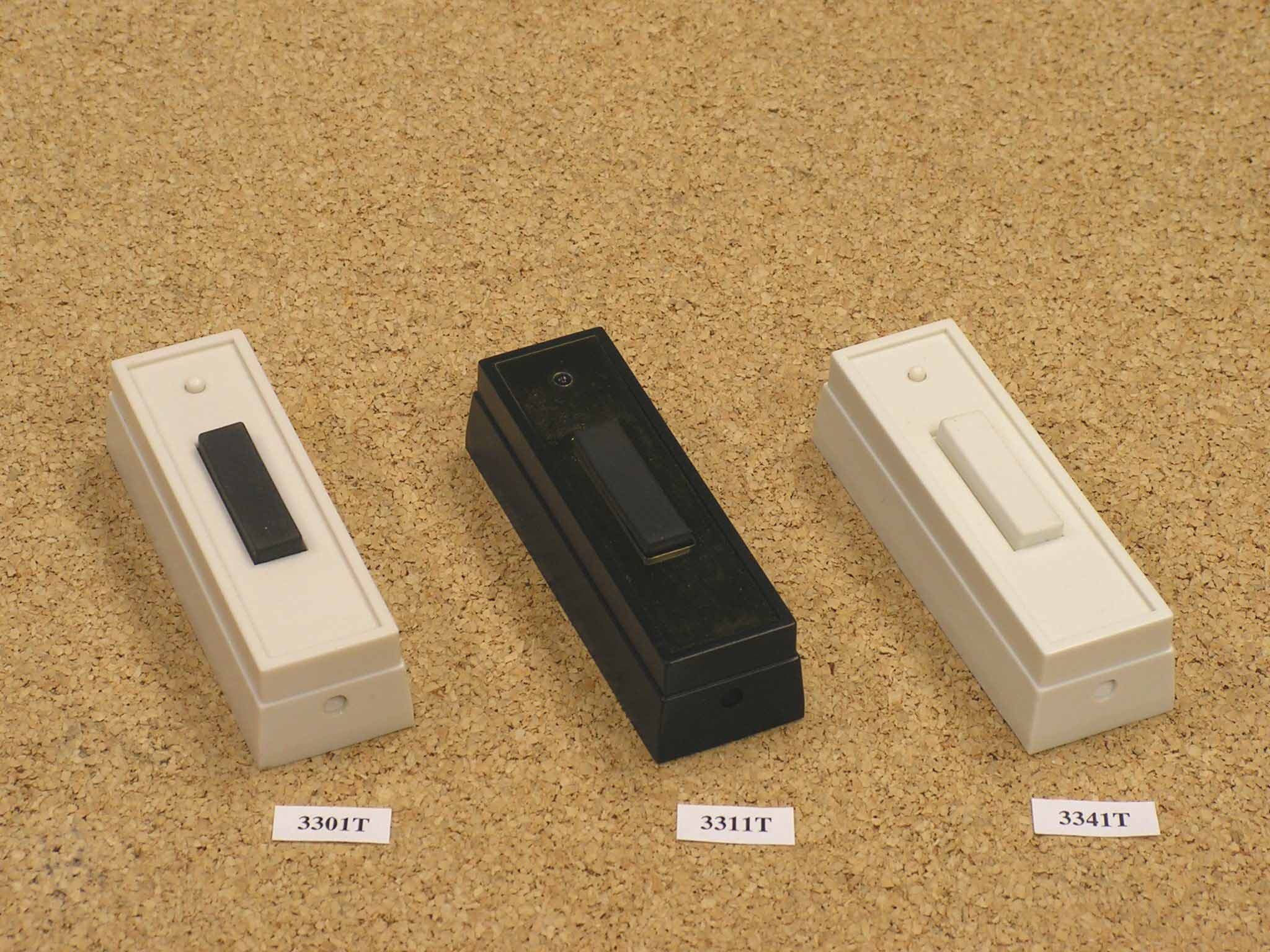
DE4-3301TB
Jan 30, 2011Wireless Door Chime Transmitter
Equipment Class
DSC - Part 15 Security/Remote Control Transmitter
DE4-HS2144T
Oct 24, 2006Motion Sensor
Equipment Class
DSC - Part 15 Security/Remote Control Transmitter
DE4-RC3922T
Sep 24, 2006Chime Receiver/Transmitter
Equipment Class
DSC - Part 15 Security/Remote Control Transmitter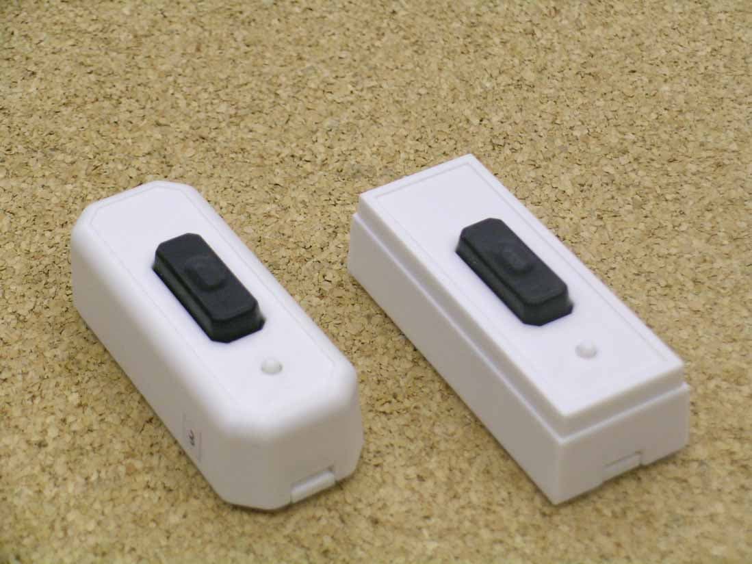
DE4-3303T
Sep 24, 2006Chime Transmitter
Equipment Class
DSC - Part 15 Security/Remote Control Transmitter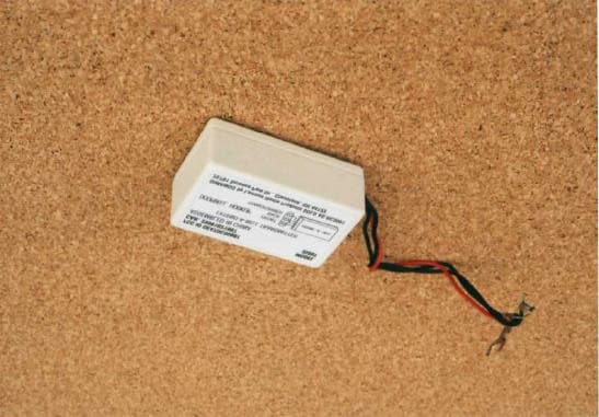
DE47DC3500T
May 01, 2002Doorbell Transmitter
Equipment Class
DSC - Part 15 Security/Remote Control Transmitter