DLAWM-5265Wireless Microphone
TOA Corporation
Click to zoom
Application Details
- Equipment Class
- TNF - Licensed Non-Broadcast Transmitter Held to Face
- Date of Grant
- Mar 20, 2011
- Application Purpose
- Original Equipment
- Date of Application
- Mar 20, 2011
- Equipment Note
- Wireless Microphone
- Frequency Range
- 614.07500000 - 697.92500000
- Company
- TOA Corporation
- Country
- Japan
Documents & Files
Document Text
Text extracted from the exhibit documents filed with the FCC. Open a document above to read the original.
Attestation Statements
1 Chris Harvey From: SS [[email protected]] Sent: Thursday, February 24, 2011 7:01 AM To: [email protected] Cc: R00/黃心怡; [email protected]; [email protected] Subject: Re: TOA Corporation, FCC ID: DLAWM-5265, Assessment NO.: AN11T0030, Notice#2 Importance: High Attachments: Exhibit-F-Test Report_rev.pdf; Exhibit-D-Test Report Cover Sheet_rev.pdf Exhibit-F-Test Report_rev.pdf ... Exhibit-D-Test Report Cover Sh... Dear Chris, Thank you for reviewing. Here is the responses below. > 1. You have changed the Emission Designator to 112KF3E using the > values in the 2M +2Dk equation for M as 6 kHz and D as 50kHz. The > Manual and the Tune Up procedure still indicate that the Maximum > Deviation (D) is 40 kHz, which is not correct. In accordance with the > measurements. Please explain where you get the Modulation Limit (M) > of 6 kHz. If the Emission Designator is changed again, please update > the reports and the IC Appendix B Test Report Cover Sheet once again. > A. Please refer to revised test report. The maximum deviation (D) was found 40kHz which is in accordance with documents. The Modulation Limit (M) was get from section 4.4 C) of the test report. IC and FCC test report were both attached. The test report cover sheet for IC was also attached. > 2. I understand that the US frequencies will be between 576-606 MHz > and 614-698MHz, but please provide a table of the 64 available > frequencies for the different rotary switches as requested previously. > In the channel selection switch that has the numbers 1-4, what happens > if the user selects any of the other 6 possible positions? There is a > switch labeled L and H and the manual says to keep the switch in the L > (factory-preset) position. What is this switch used for and why is it > available to the user? > A. The 64 Frequency Table is based on customer's request by marketing region and national regulation requirement to assign. Since the applicant's product is a new device and not getting the OEM manufacturer order yet, so there is no Assigned Table available. For Bank channel selection switch No.1-4, they have IC to control the channel. But, the other 6 Black switches are under disable status since they are no IC design. The switch labeled L and H of function is for TOA qualified service technicians to test and set up the Low and High Audio frequency of characteristics. ( Not for end user's operation) > 3. For Industry Canada, you have indicated that the Test Facility has > IC Registration number 2949A-1, but this site is registered for the > ETC facility at NO. 8, Lane 29, Wen-Ming Rd. Lo-Shan > Tsun, Kui-Shan > Hsiang, Taoyan Hsien ROC Taiwan. The test report indicates that > testing was performed at the ETC facility at # 34, Lin 5, Dingfu > Tsuen, Linkou Shiang Taipei County 24442 Taiwan, which is assigned > registration # 8641A. The Test Report Cover Letter Appendix II of > RSP-100 indicates the wrong Open Area Test Site Industry Canada Number 2 > (listed as 2949A-1, but should be 8461A-x (replace the x with the correct site used for measurements)). A. For 2949A-1 the address is NO. 8, Lane 29, Wen-Ming Rd. Lo-Shan Tsun, Kui-Shan Hsiang, Taoyan Hsien ROC Taiwan. This is the address our headquarter. The test site is located at # 34, Lin 5, Dingfu Tsuen, Linkou Shiang Taipei County 24442 Taiwan. The registration # 8641A is not actived anymore for us because we use 2949A-1 now. You can not find 8641A from the test site registration. We have applied many Canada IC approvals already and we always use 2949A-1. Please kindly help on reviewing. Thank you. S. S. Liou Section Manager EMC Testing Dept. II Electronics Testing Center, Taiwan Tel: +886-2-26023052 ext. 20 Email: [email protected] URL: http://www.etc.org.tw ----- Original Message ----- From: <[email protected]> To: <[email protected]> Cc: <[email protected]>; <[email protected]> Sent: Thursday, February 24, 2011 3:05 AM Subject: TOA Corporation, FCC ID: DLAWM-5265, Assessment NO.: AN11T0030, Notice#2 > Dear SS Liou, > > I have reviewed the Response to the TCB and IC applications for the > WM-5265 and have the following comments (please be sure you are > providing complete responses): > > 1. You have changed the Emission Designator to 112KF3E using the > values in the 2M +2Dk equation for M as 6 kHz and D as 50kHz. The > Manual and the Tune Up procedure still indicate that the Maximum > Deviation (D) is 40 kHz, which is not correct. In accordance with the > measurements. Please explain where you get the Modulation Limit (M) > of 6 kHz. If the Emission Designator is changed again, please update > the reports and the IC Appendix B Test Report Cover Sheet once again. > > 2. I understand that the US frequencies will be between 576-606 MHz > and 614-698MHz, but please provide a table of the 64 available > frequencies for the different rotary switches as requested previously. > In the channel selection switch that has the numbers 1-4, what happens > if the user selects any of the other 6 possible positions? There is a > switch labeled L and H and the manual says to keep the switch in the L > (factory-preset) position. What is this switch used for and why is it > available to the user? > > 3. For Industry Canada, you have indicated that the Test Facility has > IC Registration number 2949A-1, but this site is registered for the > ETC facility at NO. 8, Lane 29, Wen-Ming Rd. Lo-Shan > Tsun, Kui-Shan > Hsiang, Taoyan Hsien ROC Taiwan. The test report indicates that > testing was performed at the ETC facility at # 34, Lin 5, Dingfu > Tsuen, Linkou Shiang Taipei County 24442 Taiwan, which is assigned > registration # 8641A. The Test Report Cover Letter Appendix II of > RSP-100 indicates the wrong Open Area Test Site Industry Canada Number > (listed as 2949A-1, but should be 8461A-x (replace the x with the correct site used for measurements)). > > The items indicated above must be submitted before processing can 3 > continue on the above referenced application. Failure to provide th…
Text truncated - open the document above for the full version.
Attestation Statements
1 Chris Harvey From: SS [[email protected]] Sent: Tuesday, March 08, 2011 6:31 AM To: [email protected] Cc: R00/黃心怡; [email protected]; [email protected] Subject: --Unscanned-- Re: TOA Corporation, FCC ID: DLAWM-5265, Assessment NO.: AN11T0030, Notice#2 Attachments: Exhibit-L-Tune_Up Procedure_rev.pdf Exhibit-L-Tune_U p Procedure_re... Dear Chris, Regarding to Q2, please refer to attached the revised tune-up procedure. The table of frequencies are provided. Please have a review soon. Thank you. Best regards, S. S. Liou Section Manager EMC Testing Dept. II Electronics Testing Center, Taiwan Tel: +886-2-26023052 ext. 20 Email: [email protected] URL: http://www.etc.org.tw ----- Original Message ----- From: "SS" <[email protected]> To: <[email protected]> Cc: "R00/黃心怡" <[email protected]>; <[email protected]>; <[email protected]> Sent: Thursday, February 24, 2011 8:00 PM Subject: Re: TOA Corporation, FCC ID: DLAWM-5265, Assessment NO.: AN11T0030, Notice#2 > Dear Chris, > > Thank you for reviewing. Here is the responses below. > >> 1. You have changed the Emission Designator to 112KF3E using the >> values in the 2M +2Dk equation for M as 6 kHz and D as 50kHz. The >> Manual and the Tune Up procedure still indicate that the Maximum >> Deviation (D) is 40 kHz, which is not correct. In accordance with the >> measurements. Please explain where you get the Modulation Limit (M) >> of 6 kHz. If the Emission Designator is changed again, please update >> the reports and the IC Appendix B Test Report Cover Sheet once again. >> > A. Please refer to revised test report. The maximum deviation (D) was > found 40kHz which is in accordance with documents. The Modulation > Limit (M) was get from section 4.4 C) of the test report. IC and FCC > test report were both attached. The test report cover sheet for IC was > also attached. > >> 2. I understand that the US frequencies will be between 576-606 MHz >> and 614-698MHz, but please provide a table of the 64 available >> frequencies for the different rotary switches as requested 2 >> previously. In the channel selection switch that has the numbers >> 1-4, what happens if the user selects any of the other 6 possible >> positions? There is a switch labeled L and H and the manual says to >> keep the switch in the L (factory-preset) position. What is this >> switch used for and why is it available to the user? >> > A. The 64 Frequency Table is based on customer's request by marketing > region and national regulation requirement to assign. Since the > applicant's product is a new device and not getting the OEM > manufacturer order yet, so there is no Assigned Table available. > > For Bank channel selection switch No.1-4, they have IC to control the > channel. But, the other 6 Black switches are under disable status > since they are no IC design. > > The switch labeled L and H of function is for TOA qualified service > technicians to test and set up the Low and High Audio frequency of > characteristics. ( Not for end user's > operation) > > >> 3. For Industry Canada, you have indicated that the Test Facility has >> IC Registration number 2949A-1, but this site is registered for the >> ETC facility at NO. 8, Lane 29, Wen-Ming Rd. Lo-Shan > Tsun, Kui-Shan >> Hsiang, Taoyan Hsien ROC Taiwan. The test report indicates that >> testing was performed at the ETC facility at # 34, Lin 5, Dingfu >> Tsuen, Linkou Shiang Taipei County 24442 Taiwan, which is assigned >> registration # 8641A. The Test Report Cover Letter Appendix II of >> RSP-100 indicates the wrong Open Area Test Site Industry Canada >> Number (listed as 2949A-1, but should be 8461A-x (replace the x with the correct site used for measurements)). > > A. For 2949A-1 the address is NO. 8, Lane 29, Wen-Ming Rd. Lo-Shan > Tsun, Kui-Shan Hsiang, Taoyan Hsien ROC Taiwan. This is the address > our headquarter. The test site is located at # 34, Lin 5, Dingfu > Tsuen, Linkou Shiang Taipei County 24442 Taiwan. The registration # > 8641A is not actived anymore for us because we use 2949A-1 now. You > can not find 8641A from the test site registration. We have applied > many Canada IC approvals already and we always use 2949A-1. > > Please kindly help on reviewing. Thank you. > > S. S. Liou > Section Manager > EMC Testing Dept. II > Electronics Testing Center, Taiwan > Tel: +886-2-26023052 ext. 20 > Email: [email protected] > URL: http://www.etc.org.tw > > > > ----- Original Message ----- > From: <[email protected]> > To: <[email protected]> > Cc: <[email protected]>; <[email protected]> > Sent: Thursday, February 24, 2011 3:05 AM > Subject: TOA Corporation, FCC ID: DLAWM-5265, Assessment NO.: > AN11T0030, > Notice#2 > > >> Dear SS Liou, >> >> I have reviewed the Response to the TCB and IC applications for the >> WM-5265 and have the following comments (please be sure you are 3 >> providing complete responses): >> >> 1. You have changed the Emission Designator to 112KF3E using the >> values in the 2M +2Dk equation for M as 6 kHz and D as 50kHz. The >> Manual and the Tune Up procedure still indicate that the Maximum >> Deviation (D) is 40 kHz, which is not correct. In accordance with the >> measurements. Please explain where you get the Modulation Limit (M) >> of 6 kHz. If the Emission Designator is changed again, please update >> the reports and the IC Appendix B Test Report Cover Sheet once again. >> >> 2. I understand that the US frequencies will be between 576-606 MHz >> and 614-698MHz, but please provide a table of the 64 available >> frequencies for the different rotary switches as requested >> previously. In the channel selection switch that has the numbers >> 1-4, what happens if the user selects any of the other 6 possible >> positions? There is a switch labeled L and H and the manual says to >> keep the switch in the L (factory-preset) position. What is this >> switch used for and why is it available to the user? >> >> 3. For Industry Canada, you have indicated that the Test Facility has >> IC Re…
Text truncated - open the document above for the full version.
Attestation Statements
1 Chris Harvey From: SS [[email protected]] Sent: Wednesday, February 16, 2011 9:07 PM To: [email protected] Cc: R00/張文雄; R00/黃心怡; [email protected] Subject: --Unscanned-- Re: TOA Corporation, FCC ID: DLAWM-5265, Assessment NO.: AN11T0030, Notice#1 Attachments: Exhibit-C-Test_Report_rev.pdf; Exhibit-L-Tune_Up Procedure.pdf; Exhibit-K-O_D.pdf; WM-5265 antenna.pdf; Exhibit-D-ID_ Label rev.pdf; Exhibit-E-User_Manual rev.pdf Exhibit-C-Test_Re port_rev.pdf ... Exhibit-L-Tune_U p Procedure.pd... Exhibit-K-O_D.pdf (12 KB) WM-5265 antenna.pdf (48 KB Exhibit-D-ID_ Label rev.pdf (1... Exhibit-E-User_Ma nual rev.pdf ... Dear Chris, 1. The Schematics show many components that are changed depending on which band of operation the device is configured for. The available bands listed on the schematics (690-752MHz, 794-865MHz, 636-698MHz and 570-636MHz) do not align with the frequencies being requested in this application (576-606MHz and 614-698MHz). Please explain how the component changes on version and the Bank and Channel rotating switches are used to operate only in the requested frequencies of operation. A: Components are changed depending on the frequency band selected according to country regulations. For USA and Canada only frequency bands 576-606MHz and 614-698MHz are available. 2. Please provide a table of the 64 assigned frequencies compared to the rotary switch positions. The Manual has a table of frequencies that does not seem to match the available frequencies in this application (576-606MHz and 614-698MHz). A: The frequency table depends on customer required marketing region to assign and the band will comply with regulation requirement. For USA and Canada only frequency bands 576-606MHz and 614-698MHz are available. 3. The RF Power Measurement procedure for fundamental emission and spurious describes the use of the substitution Method of measurement as required by the FCC, but the test equipment list and the test setup diagrams do not show the use of the substitution antenna in place of the EUT. A: The test equipment list was revised. A note about the substitution antenna configuration was added to the test setup diagrams. Please refer to the revised test report. 4. The Occupied Bandwidth plots have been measured using a 10kHz RBW, but the BW used should be as close as possible to 1% of the emission Bandwidth (likely to be 2kHz for this device.) A: The occupied bandwidth plots were updated with 3kHz RBW. Please refer to the revised test report. 5. Please provide the Tune-Up Procedure and Schematic Diagram exhibits for this device as required by FCC 2.1033. A: Provided as attached. Note: Components are changed depending on the frequency band selected according to country regulations. For USA and Canada only frequency bands 576-606MHz and 614-698MHz are available. 2 6. Please provide the Operational Description exhibit, which is required per FCC 2.1033 , and is also listed in the Confidentiality Request letter. A: Provided as attached. Note: Components are changed depending on the frequency band selected according to country regulations. For USA and Canada only frequency bands 576-606MHz and 614-698MHz are available. 7. The Antenna is not shown in the schematics (there are pads for RF1 & RF2) and it is not clearly visible in the photos. Please provide a description and specification of the antenna. A: The antenna is the wires connecting PCB and the microphone head. Please refer to attached photo. 8. The Manual states this device has a +/-40kHz maximum deviation. This 40kHz is used for the Deviation (D) component and 15kHz is used for the Modulation (M) component in the 2M+ 2Dk Emission Designator calculation. Please show in the test report how these numbers are derived or state the occupied bandwidth in terms of values measured. A: The emission designator calculation was revised in the test report according to the values measured. Please refer to the revised test report. In addition, the user manual and ID label were alos revised. Please find them as attached. Best regards, S. S. Liou Section Manager EMC Testing Dept. II Electronics Testing Center, Taiwan Tel: +886-2-26023052 ext. 20 Email: [email protected] URL: http://www.etc.org.tw ----- Original Message ----- From: <[email protected]> To: <[email protected]> Cc: <[email protected]> Sent: Wednesday, February 02, 2011 11:00 PM Subject: TOA Corporation, FCC ID: DLAWM-5265, Assessment NO.: AN11T0030, Notice#1 > Dear SS Liou, > > You are listed as the Technical Contact for the above referenced TCB > application. The following item(s) need(s) to be resolved before the > review can be continued: > > 1. The Schematics show many components that are changed depending on which > band of operation the device is configured for. The available bands > listed on the schematics (690-752MHz, 794-865MHz, 636-698MHz and > 570-636MHz) do not align with the frequencies being requested in this > application (576-606MHz and 614-698MHz). Please explain how the component > changes on version and the Bank and Channel rotating switches are used to > operate only in the requested frequencies of operation. > > 2. Please provide a table of the 64 assigned frequencies compared to the 3 > rotary switch positions. The Manual has a table of frequencies that does > not seem to match the available frequencies in this application > (576-606MHz and 614-698MHz). > > 3. The RF Power Measurement procedure for fundamental emission and > spurious describes the use of the substitution Method of measurement as > required by the FCC, but the test equipment list and the test setup > diagrams do not show the use of the substitution antenna in place of the > EUT. > > 4. The Occupied Bandwidth plots have been measured using a 10kHz RBW, but > the BW used should be as close as possible to 1% of the emission Bandwidth > (likely to be 2kHz for this device.) > > 5. Please provide the Tune-Up Procedure and Schematic Diagram exhibits for > this device as required by FCC 2.1033. > > 6…
Text truncated - open the document above for the full version.
External Photos
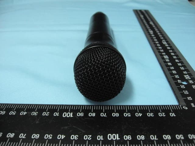
ETC Report No.:10-08-RBF-164-02 Sheet 1 of 7 Sheets FCC ID.: DLAWM-5265 Rev. 2.0 CONSTRUCTED PHOTOS of EUT 1. Side View of EUT 2. Side View of EUT ETC Report No.:10-08-RBF-164-02 Sheet 2 of 7 Sheets FCC ID.: DLAWM-5265 Rev. 2.0 CONSTRUCTED PHOTOS of EUT 3. Front View of EUT 4. Side View of EUT ETC Report No.:10-08-RBF-164-02 Sheet 3 of 7 Sheets FCC ID.: DLAWM-5265 Rev. 2.0 CONSTRUCTED PHOTOS of EUT 5. Side View of EUT 6. Rear View of EUT
ID Label/Location Info
MADE IN TAIWAN DLAWM-5265 1599B-WM5265
Internal Photos
ETC Report No.:10-08-RBF-164-02 Sheet 4 of 7 Sheets FCC ID.: DLAWM-5265 Rev. 2.0 CONSTRUCTED PHOTOS of EUT 7. Internal View of EUT ETC Report No.:10-08-RBF-164-02 Sheet 5 of 7 Sheets FCC ID.: DLAWM-5265 Rev. 2.0 CONSTRUCTED PHOTOS of EUT 8. Component View of PCB 9. Solder View of PCB ETC Report No.:10-08-RBF-164-02 Sheet 6 of 7 Sheets FCC ID.: DLAWM-5265 Rev. 2.0 CONSTRUCTED PHOTOS of EUT 10. Component View of PCB 11. Solder View of PCB ETC Report No.:10-08-RBF-164-02 Sheet 7 of 7 Sheets FCC ID.: DLAWM-5265 Rev. 2.0 CONSTRUCTED PHOTOS of EUT 12. Solder View of PCB 13. Solder View of PCB
Operational Description
WM-5265 Antenna
Parts List/Tune Up Info
WM-5225、WM-5265、WM-5325 Adjusting Procedures Test frequency AB→722.0MHz CD→830.0MHz EF→668.0MHz GH→606.0MHz (1)Transmission frequency adjustment Connect RF output to a frequency counter ,then rotate the TC1 so that the transmission frequency can be adjusted with in ±1kHz for the nominal value at no modulation. (2)RF output adjustment Connect RF output to a power meter ,then rotate the VR4 so that RF output can be adjusted to power at no modulation.. WM-5225 AB/CD/EF/GH 10.0+1mW-2 mW WM-5265 AB/CD/EF/GH 10.0+1mW-2 mW WM-5325 AB/EF/GH 10.0+1mW-2 mW WM-5325 CD 8.0+0.5mW-0.5 mW (3)Maximum deviation adjustment Connect RF output to a modulation analyzer ,then adjust the VR1 so that frequency deviation except tone signal becomes in the range of ±40±0.2kHz when modulation signal below is input from Mic input (LPF:20kHz,P-P/2) ・Modulation signal WM-5225:1kHz-14dBV ,WM-5265:1kHz,-18dBV ,WM-5325:1kHz,-28dBV TOA Microphone E Band Table Base on marketing request, there are many designed frequency tables. The submittal frequency table is one of demo Table for the TOA Microphone, which is only for reference. Note: The designed frequency table will surely comply with FCC regulation. The final Product of consigned frequency will be tuned upon distribution of marketing region request within FCC limited band. TOA Microphone F Band Table Base on marketing request, there are many designed frequency tables. The submittal frequency table is one of demo Table for the TOA Microphone, which is only for reference. Note: The designed frequency table will surely comply with FCC regulation. The final Product of consigned frequency will be tuned upon distribution of marketing region request within FCC limited band. TOA Microphone G Band Table Base on marketin g request, there are many designed frequency tables. The submittal fre quency table is one of demo Tablefor the TOA Microphone, which is onl y for reference. Note: The desi gned frequency table will surely comply with FCC regulation . The final Product of consi gned frequency will be tuned upon distribution of marketin g region request within FCC limited band . TOA Microphone H Band Table Base on marketin g request, there are many designed frequency tables. The submittal fre quency table is one of demo Tablefor the TOA Microphone, which 㫀㫊㩷㫆㫅㫃㫐㩷㪽㫆㫉㩷㫉㪼㪽㪼㫉㪼㫅㪺㪼㪅 㪙㪸㫅㫂㪈 㪙㪸㫅㫂㪉 㪙㪸㫅㫂㪊 㪙㪸㫅㫂㪋 㪇 㪌㪎㪍㪅㪈㪇㪇 㪌㪎㪍㪅㪈㪌㪇 㪌㪎㪍㪅㪋㪌㪇 㪌㪎㪍㪅㪏㪇㪇 㪈 㪌㪎㪍㪅㪌㪇㪇 㪌㪎㪍㪅㪌㪌㪇 㪌㪎㪍㪅㪏㪌㪇 㪌㪎㪎㪅㪉㪇㪇 㪉 㪌㪎㪎㪅㪇㪇㪇 㪌㪎㪎㪅㪇㪌㪇 㪌㪎㪎㪅㪊㪌㪇 㪌㪎㪎㪅㪎㪇㪇 㪊 㪌㪎㪎㪅㪍㪇㪇 㪌㪎㪎㪅㪍㪌㪇 㪌㪎㪎㪅㪐㪌㪇 㪌㪎㪏㪅㪊㪇㪇 㪋 㪌㪎㪏㪅㪊㪇㪇 㪌㪎㪏㪅㪊㪌㪇 㪌㪎㪏㪅㪍㪌㪇 㪌㪎㪐㪅㪇㪇㪇 㪌 㪌㪎㪐㪅㪊㪇㪇 㪌㪎㪐㪅㪊㪌㪇 㪌㪎㪐㪅㪍㪌㪇 㪌㪏㪇㪅㪇㪇㪇 㪍 㪌㪏㪇㪅㪎㪇㪇 㪌㪏㪇㪅㪎㪌㪇 㪌㪏㪈㪅㪇㪌㪇 㪌㪏㪈㪅㪋㪇㪇 㪎 㪌㪏㪈㪅㪐㪇㪇 㪌㪏㪈㪅㪐㪌㪇 㪌㪏㪉㪅㪉㪌㪇 㪌㪏㪉㪅㪍㪇㪇 㪏 㪌㪏㪉㪅㪎㪇㪇 㪌㪏㪉㪅㪎㪌㪇 㪌㪏㪊㪅㪇㪌㪇 㪌㪏㪊㪅㪋㪇㪇 㪐 㪌㪏㪋㪅㪍㪇㪇 㪌㪏㪋㪅㪍㪌㪇 㪌㪏㪋㪅㪐㪌㪇 㪌㪏㪌㪅㪊㪇㪇 㪘 㪌㪏㪍㪅㪎㪇㪇 㪌㪏㪍㪅㪎㪌㪇 㪌㪏㪎㪅㪇㪌㪇 㪌㪏㪎㪅㪋㪇㪇 㪙 㪌㪐㪊㪅㪉㪇㪇 㪌㪐㪊㪅㪉㪌㪇 㪌㪐㪊㪅㪌㪌㪇 㪌㪐㪊㪅㪐㪇㪇 㪚 㪌㪐㪎㪅㪎㪇㪇 㪌㪐㪎㪅㪎㪌㪇 㪌㪐㪏㪅㪇㪌㪇 㪌㪐㪏㪅㪋㪇㪇 㪛 㪍㪇㪇㪅㪎㪇㪇 㪍㪇㪇㪅㪎㪌㪇 㪍㪇㪈㪅㪇㪌㪇 㪍㪇㪈㪅㪋㪇㪇 㪜 㪍㪇㪊㪅㪉㪇㪇 㪍㪇㪊㪅㪉㪌㪇 㪍㪇㪊㪅㪌㪌㪇 㪍㪇㪊㪅㪐㪇㪇 㪝 㪍㪇㪋㪅㪏㪇㪇 㪍㪇㪋㪅㪏㪌㪇 㪍㪇㪌㪅㪈㪌㪇 㪍㪇㪌㪅㪌㪇㪇 Note: The desi gned frequency table will surely comply with FCC regulation . The final Product of consi gned frequency will be tuned upon distribution of marketin g region request within FCC limited band .
Test Report
Rev. 2.0 FCC Part 74 Subpart H EMI TEST REPORT of E.U.T. : WIRELESS MICROPHONE FCC ID. : DLAWM-5265 Model No. : WM-5265 Working Frequency : 576 – 606 MHz; 614.075 – 697.925MHz for APPLICANT : TOA Corporation ADDRESS : 2-1 Takamatsu-cho, Takarazuka-shi, Hyogo-ken, 665-0043, Japan Test Performed by ELECTRONICS TESTING CENTER (ETC) , TAIWAN NO. 34, LIN 5, DINGFU TSUEN, LINKOU SHIANG TAIPEI COUNTY, TAIWAN, 24442, R.O.C. TEL : (02)26023052 FAX : (02)26010910 http:// www.etc.org.tw ; e-mail:[email protected] Report Number : 10-08-RBF-164-02 ETC Report No.:10-08-RBF-164-02 FCC ID.: DLAWM-5265 Rev. 2.0 TEST REPORT CERTIFICATION Applicant : TOA Corporation 2-1 Takamatsu-cho, Takarazuka-shi, Hyogo-ken, 665-0043, Japan Manufacturer : Dynatron Industrial Co., Ltd. No. 89, Din Pin Rd. Ray Fong Industrial Area, Ray Fong Town, Taipei Hsien, Taiwan, R.O.C. Description of EUT : a) Type of EUT : WIRELESS MICROPHONE b) Trade Name : TOA c) Model No. : WM-5265 d) FCC ID : DLAWM-5265 e) Working Frequency : 576 – 606 MHz; 614.075 – 697.925MHz f) Power Supply : Battery DC 1.5V Regulation Applied : FCC Rules and Regulations Part 74 Subpart H (2009) I HEREBY CERTIFY THAT; The data shown in this report were made in accordance with the procedures given in ANSI C63.4 and the energy emitted by the device was founded to be within the limits applicable. I assume full responsibility for accuracy and completeness of these data. ETC Report No.:10-08-RBF-164-02 FCC ID.: DLAWM-5265 Rev. 2.0 Issued Date : Mar. 21, 2011 Test Engineer : ( Vincent Chang, Engineer ) Check By : ( Charles Wang, Supervisor ) Approve & Authorized : Will Yauo, Manager EMC Dept. II of ELECTRONICS TESTING CENTER, TAIWAN ETC Report No.:10-08-RBF-164-02 FCC ID.: DLAWM-5265 Rev. 2.0 Table of Contents Page 1. GENERAL INFORMATION ............................................................................................................................... 1 1.1 PRODUCT DESCRIPTION........................................................................................................................................... 1 1.2 TEST METHODOLOGY.............................................................................................................................................. 1 1.3 TEST FACILITY........................................................................................................................................................ 1 2. REQUIREMENTS OF PROVISIONS ................................................................................................................ 2 2.1 DEFINITION............................................................................................................................................................. 2 2.2 FREQUENCIES AVAILABLE...................................................................................................................................... 2 2.3 REQUIREMENTS FOR RADIO EQUIPMENT ON CERTIFICATION.................................................................................. 2 2.4 LABELING REQUIREMENT........................................................................................................................................ 3 3. OUTPUT POWER MEASUREMENT ................................................................................................................ 4 3.1 PROVISION APPLICABLE.......................................................................................................................................... 4 3.2 MEASUREMENT PROCEDURE................................................................................................................................... 4 3.3 TEST DATA.............................................................................................................................................................. 6 3.4 RESULT CALCULATION............................................................................................................................................ 8 3.5 TEST EQUIPMENT.................................................................................................................................................... 8 4. MODULATION CHARACTERISTICS ............................................................................................................. 9 4.1 PROVISIONS APPLICABLE........................................................................................................................................ 9 4.2 MEASUREMENT METHOD........................................................................................................................................ 9 4.3 MEASUREMENT INSTRUMENT................................................................................................................................10 4.4 MEASUREMENT RESULT........................................................................................................................................ 10 5. OCCUPIED BANDWIDTH OF EMISSION .................................................................................................... 17 5.1 PROVISIONS APPLICABLE...................................................................................................................................... 17 5.2 MEASUREMENT METHOD...................................................................................................................................... 17 5.3 OCCUPIED BANDWIDTH TEST EQUIPMENT............................................................................................................ 17 5.4 BANDWIDTH MEASURED....................................................................................................................................... 18 5.4.1 Input Level Derived...................................................................................................................................... 18 5.4.2 Occupied Bandwidth Plotted.......................................................................…
Text truncated - open the document above for the full version.
Test Setup Photos
ETC Report No.:10-08-RBF-164-02 Sheet 35 of 40 Sheets FCC ID.: DLAWM-5265 Rev. 2.0 6.6 Radiated Measurement Photos
Contact Information
Applicant
Tomohisa Tanaka
Test Firm
Electronics Testing Center, TaiwanWill Yauo
Technical Specifications
| # | Rule Parts | Frequency Range | Power Output | Emission | Tolerance |
|---|---|---|---|---|---|
| 2 | 74 | 614.075 MHz - 697.925 MHz | 8.91 mW | 92K0F3E | 0.005 % |
Other Applications from TOA Corporation
DLAS5HDX
Jul 30, 2014Wireless Microphone
Equipment Class
TBC - Licensed Broadcast Station Transmitter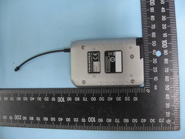
DLAS5LTX
Jul 30, 2014UHF Wireless Transmitter
Equipment Class
TBT - Licensed Broadcast Transmitter Worn on Body
DLAWM-5325
Jul 20, 2011Wireless Transmitter
Equipment Class
TBT - Licensed Broadcast Transmitter Worn on Body
DLAWM-5270B
Mar 29, 2011Wireless Microphone
Equipment Class
TNF - Licensed Non-Broadcast Transmitter Held to Face
DLAWM-5225
Mar 28, 2011Wireless Microphone
Equipment Class
TNF - Licensed Non-Broadcast Transmitter Held to Face