DMOAAGPSFWireless audio system
Sennheiser Electronic Corp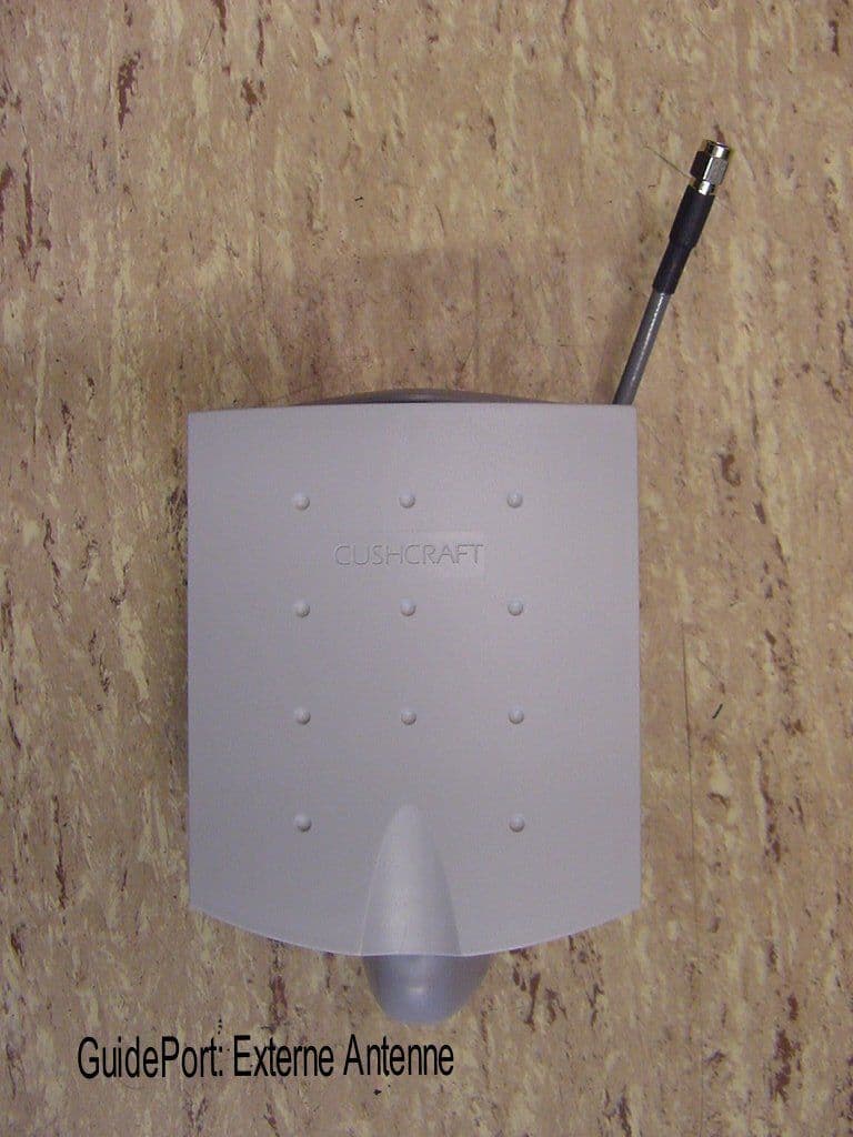
Click to zoom
Application Details
- Equipment Class
- DXX - Part 15 Low Power Communication Device Transmitter
- Date of Grant
- Jul 01, 2001
- Application Purpose
- Original Equipment
- Date of Application
- Mar 21, 2001
- Equipment Note
- Wireless audio system
- Frequency Range
- 2401.90000000 - 2482.30000000
- Company
- Sennheiser Electronic Corp
- Country
- United States
Documents & Files
Document Text
Text extracted from the exhibit documents filed with the FCC. Open a document above to read the original.
Users Manual
- Aktive Antenne für GuidePort - - Spezifikation - Version 1.4 - Vertraulich - Wedemark, den 27. November 2000 Udo Müller,Abt. ELE Sennheiser electronic GmbH & Co KG Am Labor 1 30900 Wedemark Tel.: 05130/600559 Fax: 05130/600330 Udo Müller, Abt ELE27. November 2000Seite 2 Änderungshistorie Version DatumBemerkung 1. 013. 01.1999Grundspezifikation AAU 1.102.03.1999Änderung der HF-Übertragungskanäle; Modifikation des Datenaustauschs zw. DSP (CCU) und PIC (AAU) Änderung der Spannungsversorgung der AAU über die CCU 1.215.04.1999Änderung der Referenzfrequenz des Oszillators Ergänzung der Baugruppenbeschreibung Ergänzung der Schnittstellenbeschreibung 1.322.04.1999Kap. 2.1.6 PIC-Controller Kap. 3.2.2 Softwarschnittstelle CCU->AAU 1.427.11.2000Kap. 3.2.2 Softwarschnittstelle CCU->AAU: Einarbeitung der Ergänzungen von IKHF Udo Müller, Abt ELE27. November 2000Seite 3 0 Einleitung Die Aktive Antenne ist die von der Central Unit abgesetzte HF-Einheit zur Übertragung digitaler Daten des Systems GuidePort im 2,4GHz ISM-Band. 1 Allgemeines Technische Anforderungen: •Abstrahlung von digitalen Datenstömen im ISM-Band 2,4GHz. •Modulationsverfahren: 2-FSK mit einem Modulationsindex von μ= 0,5...0,7μ= ⋅ æ è ç ö ø ÷ 2f f bit ∆ mit fbit= 1,024MHz •Max. Sendeleistung von10mW (= 10dBm) in Europa, 1mW ( = 0dBm ) in den USA) über Programmierung in Stufen abzudämpfen. •95 Kanäle im 864kHz-Raster durch PLL programmierbar •Verarbeitung von Daten im LVDS-Standard mit einer Datenrate von bis zu 2Mbit/s. •Adressierbarkeit des Moduls •Einstellung des HF-Übertragungskanals, der Sendeleistung, des MTS-Umschalters und Verwendung einer internen oder externen Antenne über Fernspeisung durch die Central Unit. •Temperaturbereich: -20°C ... +55°C •Verwendung der Aktiven Antenne als Master- und Slave-Modul •Adressierung des Moduls über einen von aussen zugänglichen DIP-Switch Udo Müller, Abt ELE27. November 2000Seite 4 2 Die Baugruppen 2.1 DC/DC-Wandler Für die Versorgung der aktiven Antenne steht auf der LVDS-Schnittstelle eine Spannung von 15V ±10% zur Verfügung. Diese Spannung wird zunächst mit einem Schaltregler auf 5V und anschließend mit LDO-Reglern auf 3,3V für die Versorgung der analogen und der digitalen Schaltungsteile gewandelt. 2.2 LVDS-Receiver Der LVDS-Receiver transformiert den auf der Leitung von der CCU zur Aktiven Antenne verwendeten LVDS-Pegel in 3,3V-Logigpegel. Diese Schnittstelle ist für die Leitungen MTS1/RXD und MTS2 vorgesehen. 2.2 LVDS-Transmitter Der LVDS-Transmitter tranformiert den 3,3V-Logigpegel der Signale MTS1/RXD und MTS2 zur Weiterleitung über ein 8pol-Verbindungskabel in den LVDS-Leitungspegel zur Ansteuerung einer weiteren Aktiven Antenne an einer Central-Unit. 2.3 MTS-Umschalter Je nach Konfigurierung soll die Aktive Antenne den über die LVDS-Schnittstelle übertragenen MTS1 oder MTS2 von der Central-Unit übertragen. Die Ansteuerung des Umschalters erfolgt durch den PIC-Controller. 2.5 Datenfilter Durch das Datenfilter soll das rechteckförmige Datensignal bandbegrenzt werden. Diese Begrenzung des Basisbandes führt zu einer Bandbegrenzung des HF-Signals. 2.6 VCO Der VCO erzeugt die Tragerfrequenz des verwendeten HF-Kanals. Die Einstellung der Frequenz erfolgt durch vom Loopfilter bereinigte Phasendetektorspannund der PLL. Die FSK-Modulation entsteht durch die Addition von Abstimmspannung mit dem band- und amplitudenbegrenzten Datensignal. Udo Müller, Abt ELE27. November 2000Seite 5 2.7 PLL Mit Hilfe einer PLL wird die Sendefrequenz der Aktiven Antenne eingestellt. Für die Übertragungskanäle 0...94 sind die Register der PLL durch den PIC zu programmieren. Kanal Frequenz [MHz] Kanal Frequenz [MHz] Kanal Frequenz [MHz] 322428,704642456,352 12401,920332429,568652457,216 22402,784342430,432662458,080 32403,648352431,296672458,944 42404,512362432,160682459,808 52405,376372433,024692460,672 62406,240382433,888702461,536 72407,104392434,752712462,400 82407,968402435,616722463,264 92408,832412436,480732464,128 1 024 09,696422437,344742464,992 112410,560432438,208752465,856 122411,424442439,072762466,720 132412,288452439,936772467,584 142413,152462440,800782468,448 152414,016472441,664792469,312 162414,88 0482442,5288 0247 0,176 172415,744492443,392812471,040 182416,608502444,256822471,904 192417,472512445,12 0832472,768 2 02418,336522445,984842473,632 212419,200532446,848852474,496 222420,064542447,712862475,360 232420,928552448,576872476,224 242421,792562449,44 0882477, 088 252422,656572450,304892477,952 262423,52 0582451,1689 02478,816 272424,384592452,032912479,680 282425,2486 02452,89692248 0,544 292426,112612453,76 0932481,4 08 3 02426,976622454,624942482,272 312427,84 0632455,488 Udo Müller, Abt ELE27. November 2000Seite 6 2.8 Loopfilter Durch das Loopfilter wird die Phasendetektorspannung bereinigt. Der DC-Wert dieser bereinigten Spannung stellt die Schwingfrequenz des VCO ́s ein. Die Grenzfrequenz des Loopfilters muß so dimensioniert werden, daß das Modulationssignal durch die PLL nicht ausgeregelt werden. 2.9 Additionsstelle Die Additionsstelle kombiniert die gefilterte Phasendetektorspannung mit dem zu übertragenden MTS-Signal. Als Ausgangssignal entsteht eine mit dem MTS-Signal modulierte Abstimmspannug, die die FSK-Modulation des VCO ́s mit dem gewünschten Frequenzhub bewirkt. 2.10 Referenzoszillator Der Referenzoszillator stellt die Referenzfrequenz für die PLL und die Taktfrequenz für den PIC zur Verfügung. Frequenz:10,368MHz Toleranz: ±10ppm Pegel:3,3V-Logigpegel Der Quarz ist folgendermaßen spezifiziert: Frequenz:10,368MHz Abgleich-Toleranz: ±10ppm Temperatur-Toleranz: ±5ppm (0...55°C) ±10ppm (55...65°C) Resonanz und Last:Parallesresonanz mit CL=25pF 2.11 Treiberstufe Dem VCO folgt eine Treiberstufe, die das zu sendende ISM-Band Ausgangssignal verstärkt. Udo Müller, Abt ELE27. November 2000Seite 7 2.12 Dämpfungssteller Mit dem Dämpfungssteller soll die maximal zulässige Sendeleistung der Aktiven Antenne abgesenkt werden. Die Ansteuerung des Dämpfungsstellers erfolgt über den PIC. Die Vo…
Text truncated - open the document above for the full version.
Users Manual
GuidePort – EMP System Manual Version 1.0 of 27 July 2000 Sennheiser electronic GmbH & Co. KG Am Labor 1 30900 Wedemark Germany GuidePort: System Manual27. November 2000Seite 2 1 GuidePort Wireless Audio Transmission GuidePort is a local area broadcast system for use in museums, visitor centers and at exhibitions. GuidePort features a characteristic cell structure, the so-called cells being defined areas of information and entertainment. These areas are supplied byCell Transmitterswhich send digitally coded information via anActive Antenna Unitto portableReceivers. The transmitted data can be any audio information, for example comments or music. The audio signals are picked up by bodypack receivers which play the audio program directly via headphones. The various audio programs (events) can be triggered automatically bymagnetic field identifiers. The diagram on the next page shows GuidePort’s system hierarchy. At the top level are the GuidePort installations. Each installation carries a specific code transmitted via RF. Whenever a GuidePort receiver recognizes a new installation code, it will automatically collect the installation-specific control data. This data is mainly the so-called Event Assign Table which defines the receiver’s “reactions” to the 255 possible event numbers available in each installation, making the receiver compatible with other separate, independent GuidePort installations. An installation can be seen as a macro cell. Each installation can be organized in up to 255 cells and contains up to 255 real-time audio events. GuidePort: System Manual27. November 2000Seite 3 GuidePort Installation INST. No. 1 GuidePort Installation INST. No. 3 GuidePort Installation INST. No. 2 cell 1 cell 2 cell 3 cell 4 ... cell 255 cell 5 GuidePortCell with one or more Cell Transmitters Event 1Event 2 Event 3 Event 5 Event 4 Event 6 Event N Oneinstallation can handle up to 255 events which may be organized in up to 255 cells GuidePort System Hierarchy One celltransmitter can handle up to 4 mono audio channels and transmit them on one RF channel GuidePort: System Manual27. November 2000Seite 4 Cell Transmitter Central Unit PCwith •GP Central Unit Software •Sound card with a samplingrateof 32 kHz •G7++ converter and announcement software Base Station PC with Cell Transmitter Loader Software Base Station PC with Cell Transmitter Loader Software Audio Source 1 -4 PC Network Base Station PC with Cell Transmitter Loader Software USB Hub USB USB Hub Audio Source 1 -4 Active Antenna Unit RF CH 1 Cell Transmitter Active Antenna Unit RF CH 4 Cell Transmitter Event #3 Event #4 Event #5 Event #6 GP Receiver Ext. Antenna (opt.) Event #2 Event #1 Exhibition room 1 Exhibition room 2 Exhibition room 3 Exhibition room 7 Technical room 1 LVDS LVDS USB Exhibition room 5 Exhibition room 6 Exhibition room 4 Technical equipment required for an exhibition with GuidePort Supervisor GuidePort: System Manual27. November 2000Seite 5 2 Hardware Components of the System 2.1 Central Unit PC The Central Unit PC with its Central Unit Software is at the heart of the GuidePort system. It serves to configure the entire GuidePort installation with its cells, transmitters, events and identifiers. Via a network, the Central Unit PC is connected with all Base Station PCs of the GuidePort installation. 2.2 Base Station PC The Base Station PC with its Cell Transmitter Loader Software detects the IDs of all Cell Transmitters connected to it via a USB. The Base Station PC will transmit the configuration files created by the Central Unit Software to the Cell Transmitters. 2.3 Cell Transmitter 2.3.1 Description A Cell Transmitter is a digital unit which picks up prepared MTS data and combines them with installation-specific control tables and the real-time audio information from its four analog audio inputs. Via an LVDS interface, the entire data stream is sent to an Active Antenna Unit where FSK modulation and RF conversion take place. The transmission of the MTS data is done in a cyclic manner. The cable length between the Cell Transmitter and the Active Antenna Unit may amount to up to 150 m, which ensures a convenient installation of the local antennas. 1234 Analog RTA Inputs Cell Controller Unit USB Interface LVDS Interface Data Download To Active Antenna Unit Base Station GuidePort: System Manual27. November 2000Seite 6 2.3.2 Hardware Interfaces a)Front panel Headphone Outputs Allow you to monitor the audio signals transmitted to the receivers. b)Rear panel USB IN: Input socket for the USB cable from the Base Station PC. ANALOG IN SYM.: Inputs for connecting your audio sources to the transmitter. There are four balanced inputs, you can either connect 4 mono sources, 2 mono sources and 1 stereo source or 2 stereo sources. For a stereo audio source, you will need two sockets (left and right channel), please use inputs 1 & 2 and/or 3 & 4. Connect the left audio channel to socket No. 1 or 3, the right audio channel to No. 2 or 4, respectively. The following table shows how to connect your audio sources to the GuidePort Cell Transmitter: Number and kind of audio sources Input No. 1Input No. 2Input No. 3Input No. 4 4 mono (m)mmmm 2mono(m),1stereo(s)mms,lefts,right 2 stereo (s)s, lefts, rights, lefts, right AAU OUT Output for connection of an Active Antenna Unit. Use a shielded, 8-wire twisted pair cable (4 individually twisted pairs) for connection. This cable supplies the Active Antenna Unit with DC and the digital data stream to be transmitted. SETSET GuidePortSR3000-2 TX ITX II TX II AAU OUT 0 I USB IN ANALOG IN SYM. TIP: + RING:- 1 234 TX I AAU OUT USB IN ANALOG IN SYM. TIP: + RING:- 1 234 GuidePort: System Manual27. November 2000Seite 7 2.3.3 User Interface (Display and Controls) Menu layout of the GuidePort Cell Transmitter: AAU SETTINGS SETSET AAU 01 AAU 02 AAU 08 RF CHxx EXT ANT xx MTS xx RF ATTEN xx SET SET SET 1...95 NC ON OFF NC 01 02 OFF 00...06 TX OK CCU ID xxx SET SET RTA VOLVOL xx SET Max. 32 Default 16 Min.1 SET RTA…
Text truncated - open the document above for the full version.
Users Manual
GuidePortSoftware Short User Guide Version 1.0 of 27 July 2000 Sennheiser electronic GmbH&Co. KG Am Labor 1 30900Wedemark Germany GuidePort: Software Description27. Juli 2000Seite 2 Contents 1 SETTING UP THE BASE STATION HARDWARE...................................................3 2 INSTALLING THE CELL TRANSMITTER LOADER SOFTWARE.....................4 3 CENTRAL UNIT PC .......................................................................................................6 3.1 CENTRAL UNIT SOFTWARE...........................................................................6 3.2 DATABASE DRIVER...........................................................................................7 3.3 PALMTOP SOFTWARE .....................................................................................8 4 CREATING A GUIDEPORT INSTALLATION FOR YOUR EXHIBITION..........9 5ANNOUNCEMENTS.....................................................................................................18 6 DOWNLOADING THE CONFIGURATION FILES TO THE GUIDEPORT TRANSMITTERS ..........................................................................................................19 GuidePort: Software Description27. Juli 2000Seite 3 1Setting Up the Base Station Hardware •First connect all Cell Transmitters via a USB hub to a Base Station PC. •Then connect the Base Station PC to your local area network. •Via the network, the Base Stations are connected to a Central Unit PC. Cell Transmitter Cell Transmitter Cell Transmitter Cell Transmitter USB-Hub Cell Transmitter Cell Transmitter Cell Transmitter Cell Transmitter USB-Hub Base Station Base Station Base Station PC with CT Loader Base Station PC with CT Loader Cental Unit PC with: •Sound Card, capable of 32 kHz sampling rate •G7.22++ converter and announcement software •GP CU software Figure 1: SystemSet-Up N.B.: Instead of a local area network solution with separate Central Unit PC and Base Station PC, you can also work with only one PC or laptop computer with Windows 98™ and a USB connector. Via the USB, the Base Station PC detects the IDs of all Cell Transmitters connected to it, and transfers the configuration files to the Cell Transmitters. (N.B.: These configuration files will be created later with the Central Unit Software, see chapter 4) When starting the Base Station PC or hot plugging the Cell Transmitters into the PC, a Windows 98 message will inform you about the detection of a new USB device. Please insert the „USB Driver“ disk to install the missing driver. Now your hardware is ready for the installation of the Cell Transmitter Loader Software. Local Area Network GuidePort: Software Description27. Juli 2000Seite 4 2Installing the Cell Transmitter Loader Software •Insert the „Cell Transmitter Loader“ disk and run „setup.exe“ to install the Cell Transmitter Loader Software on your Base Station PC. The following screen will be shown: •Click [Next] to continue installation. •The InstallShield assistant will suggest a destination directory where to install the program files. You may either accept the proposed path or click [Browse] to choose a different path. Please make a note of the path as you will need it later for setting up the cell transmitters. GuidePort: Software Description27. Juli 2000Seite 5 Installation will then continue. The Shield assistant will close automatically when the program has been installed. •Now start the Cell Transmitter Loader program from the program directory of the Windows 98™ start menu. The following window will be displayed: •Switch on all Cell Transmitters connected to your Base Station PC. Click [Find Transmitter] to locate the transmitters. The number and IDs of all transmitters found will be displayed: Number of transmitters found Transmitter ID Buttons for selecting for a transmitter GuidePort: Software Description27. Juli 2000Seite 6 The Cell Transmitter Loader Software will create a „TXxxxxxx.ini“ file in its destination path for every transmitter it has found. These files will be used later for configuring the transmitters with the Central Unit Software. Now you have to install the Central Unit Software on your Central Unit PC. N.B.: Instead of a local area network solution with separate Central Unit PC and Base Station PC, you can also work with only one PC or laptop computer with Windows 98™ and a USB connector. 3Central Unit PC The Central Unit PC is at the heart of the GuidePort system. It serves to configure the entire GuidePort installation with its cells, transmitters, events and identifiers. 3.1 Central Unit Software •Insert the „Central Unit Software“ disk and run „setup.exe“ to install the program on your Central Unit PC. The following screen will be shown: •The InstallShield assistant will then suggest a destination directory where to install the program files. You may accept the proposed path or click [Browse] to choose a different directory. •In order to run the Central Unit Software, you now have to install the GuidePort database driver. GuidePort: Software Description27. Juli 2000Seite 7 3.2 Database Driver •Insert the first disk of „GuidePort Database Driver Ver. 3.5“ and start „Setup.exe“ to install the driver. The following window will be displayed: •Select both items and click [Next] to continue. The next window contains additional, optional data formats: •Select all formats and click [Next] to start the installation. •When the program asks for disks 2 and 3, insert the respective disk and click [OK] to continue installation. •When the installation has been completed a message will be displayed. Click [OK] to leave the InstallShield assistant. GuidePort: Software Description27. Juli 2000Seite 8 3.3 Palmtop Software To complete the configuration of your GuidePort installation, install the identifier programming software on your 3Com Palm IIIx or PalmV. •First install the Palm™ Desktop Organizer Software as described in the palmtop’s manual. •The GuidePort.prc application is contained on the „GP Palmtop Softwar…
Text truncated - open the document above for the full version.
Attestation Statements
Sennheiser electronic GmbH & Co. KG Am Labor 1 30900 Wedemark Germany Telefon +49 (5130) 600-0 Telefax +49 (5130) 600-300 Sennheiser electronic•Postfach100264•30892 Wedemark Sennheiser electronic GmbH & Co. KG•Sitz: 30900 Wedemark OT Wennebostel•Amtsgericht Burgwedel HRA 1218 phG: Sennheiser Beteiligungsgesellschaft mbH•Amtsgericht Burgwedel HRB 2498•Geschäftsführer: Volker Bartels, Dr. Heinrich Esser, Rolf Meyer Vorsitzender des Aufsichtsrats: Prof. Dr. sc. techn. Jör gSennheiser Kreissparkasse HannoverNord LB HannoverDG Bank AG Hannover Kto.-Nr. 1070 287 659Kto.-Nr. 101 027 225Kto.-Nr. 40 469 BLZ 250 502 99BLZ 250 500 00BLZ 250 600 00 Cetecom ICT Services GmbH Gerald Schmidt Certification Manager International Type Approval Untertürkheimer Str. 6 – 10 66117 Saarbrücken DurchwahlDatum -56509. Apr. 2001 FCCApprovalOfTheGuidePortSystem Dear Mr. Schmidt, please find our answers to the FCC questions below: 1. To qualify for professional installation, Sennheiser must explain why the hardware cannot simply be purchased and installed by the average (technically inclined) person. This system is a complex multi-node distributed system designed to provide real time audio at a specific display or demonstration in areas such as museums, galleries, expositions, etc., At the discretion of the viewer. The system combines the strategies of a central computer controller, hardwired cabling between active display units, and coded transceivers allowing individual control of the requested information for a specific display. Specialized computer programs are required and provided only by Sennheiser to the installer that setup the requisite computer protocols. This system is designed to be installed during the construction phase or during a remodeling phase for the exhibit. All system components including cabling are provided or specified by Sennheiser in the case of non-rf related cables. 2. The device cannot be sold retail, to the general public or by mail order. It must be sold to dealers. Sennheiser currently markets this product directly to commercial establishments only where a need for a distributed system to assist the viewing public is needed. It is not sold nor intended to be sold to the general public or by mail order. Future plans of Sennheiser are to market the product to its licensed dealers provided sufficient acceptance warrants distribution of this nature. 3. Requires professional installation. Installation must be controlled. All installations are under the control of Sennheiser or its authorized installers 209.04.01Grt 4. Installation by licensed professionals is required (EUT sold to dealer who hires installers). As previously stated, current marketing is directly through Sennheiser and Sennheiser authorized installers are required to do the installation. Authorized installers will be either Sennheiser personnel or professional installers who have received the necessary training by Sennheiser personnel. 5. Installation requires special training (special programming, access to keypad, field strength measurements made). What is unique, sophisticated, complex, or specialized about your equipment which requires it to be installed by a professional installer? Proper attachment of all interconnect cabling is always critical just as it would be with any distributed system such as a perimeter protection system or master antenna system installed. In addition, individual cells must be specially programmed for frequency as a function of the frequency of the adjacent cells. Since installations are indoors, multipath problems must be accounted for. Final evaluation of system performance and fine tuning system performance will be done when necessary using radiated field measuring equipment. 6. Please explain how the EUT meets all the above criteria for professional installation. As explained above, this is a very complex system. Proper operation requires knowledgeable technicians that have received the required training. In view of the above, the Sennheiser system meets the criteria as specified in the oet letter. Best regards, SENNHEISER Electronic GmbH & Co. KG Dr. Enno Grotelüschen Project Management
Block Diagram
Udo Müller, Abt ELE 27. November 2000 Seit e GuidePortAM3000:ActiveAntennaUnit: 2,4...2,4835GHz LVDS- Receiver LVDS- Transmitter Low pass filter MTS1/RXD MTS2 MTS- switch VCO Ampli- fier PLL PIC f ref Voltage controlled ampiifier TXD HF/PIC +15V Antenna- switch Int./Ext. Internal Chip- Antenna External Antenna connected via SMA DC/DC- converter 3 Loop- filter ISM-Filter 3,3V line driver 5V +
Cover Letter(s)
Mar 28, 2001 CONFIDENTIALITY REQUEST Federal Communications Commission Authorization and Evaluation Division 7435 Oakland Mills Road Columbia, MD 21046 Re:Sennheiser Electronic Corp. FCC ID:DMOAAGPSF Gentlemen: Sennheiser Electronic Corp., herein submits an Application for Equipment Authorization to be followed by submission of a fee for $1130.00 along with Form 159 for certification of a low power communications device transmitter under FCC Rules Part 15 as required by the FCC Rules. Sennheiser requests, pursuant to 47CFR 0.459, post grant confidentiality for portions of the material contained in this application such that the identified material will be withheld from public inspection following the grant of this authorization. This material, as indicated by request for confidentiality of the item during the electronic submission process and further identified below, includes: 1. Circuit diagrams submitted as Equipment Authorization Electronic Filing attachment: "schematics". Specifically, this exhibit contains information relating to circuit function and complexity that could be of benefit to competitors. The material contains trade secrets and confidential information that Sennheiser does not customarily release to the public and which is otherwise not generally available to the public. Please contact the undersigned by phone at 410-531-3439, by fax at 410-531-0807, by email at [email protected], or by correspondence at the address below if there are any further questions or additional information needed concerning this filing. Rega rds, (signed) Phillip Inglis, TRP/Cetecom b.v.b.a. 14085 Howard Rd. Dayton, MD. 21036
Cover Letter(s)
System Overview: This system is designed to provide individual control for audio messages pertaining to a specific display in various exhibit situations such as museums and other exibitions visited by the public. By utilizing a small inductive loop transmitter, an individual remote active antenna in front if the specific exhibit is activated enabling the visitor to hear a specific message relayed from a central control unit via cable to the remote active antenna. Approximately 94 individual channels are available allowing each remote active antenna to operate individually without interfering with other units in nearby exhibit halls. A detailed description of the installation requirements and equipment setup is provided in the system manual which has been filed. Due to its complexity, this system is professionally installed and qualifies for exemption from the unique connector rules applicable to part 15 transmitters. A professional installation manual is currently under draft and will be provided as soon as it is available. Under current Part 15 interpretations, test data on a single unit is submitted since transmitters operate on individual frequencies. Radiated emissions data has been provided for frequencies at low, middle, and high end of the band. Phillip Inglis
Cover Letter(s)
June 18, 2001 CONFIDENTIALITY REQUEST Federal Communications Commission Authorization and Evaluation Division 7435 Oakland Mills Road Columbia, MD 21046 Re:Sennheiser Electronic Corp. FCC ID:DMOAAGPSF Gentlemen: Sennheiser hereby modifies the original confidentiality request letter to include the active antenna manual submitted on June 19, 2001. The original letter text follows as modified to include the request for confidentiality of the active antenna manual. Sennheiser Electronic Corp., herein submits an Application for Equipment Authorization to be followed by submission of a fee for $1130.00 along with Form 159 for certification of a low power communications device transmitter under FCC Rules Part 15 as required by the FCC Rules. Sennheiser requests, pursuant to 47CFR 0.459, post grant confidentiality for portions of the material contained in this application such that the identified material will be withheld from public inspection following the grant of this authorization. This material, as indicated by request for confidentiality of the item during the electronic submission process and further identified below, includes: 1. Circuit diagrams submitted as Equipment Authorization Electronic Filing attachment: "schematics". 2. Active Antenna Manual submitted as Equipment Authorization Electronic Filing attachement: “Active Antenna Manual with Technical Description”. Specifically, these exhibit contains information relating to circuit function and complexity that could be of benefit to competitors. The material contains trade secrets and confidential information that Sennheiser does not customarily release to the public and which is otherwise not generally available to the public. Please contact the undersigned by phone at 410-531-3439, by fax at 410-531-0807, by email at [email protected], or by correspondence at the address below if there are any further questions or additional information needed concerning this filing. Regards, (signed) Phillip Inglis, TRP/Cetecom b.v.b.a. 14085 Howard Rd. Dayton, MD. 21036
ID Label/Location Info
This equipment will have the following FCC ID label located on the bottom of the unit. This device complies with Part 15 of the FCC Rules. Operation is subject to the following two conditions: (1) this device may not cause harmful interference, and (2) this device must accept any interference received, including interference that may cause undesired operation. FCC ID:DMOAAGPSF
ID Label/Location Info
This device complies with Part 15 of the FCC Rules. Operation is subject to the following two conditions: (1) this device may not cause harmful interference, and (2) this device must accept any interference received, including interference that may cause undesired operation . The equipment label will be located on the bottom of the unit as indicated above. Phillip Inglis TRP/Cetecom bvba FCC ID:DMOAAGPSF
Internal Photos
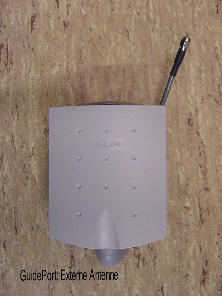
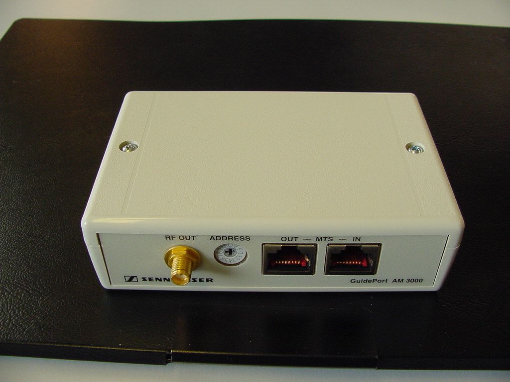
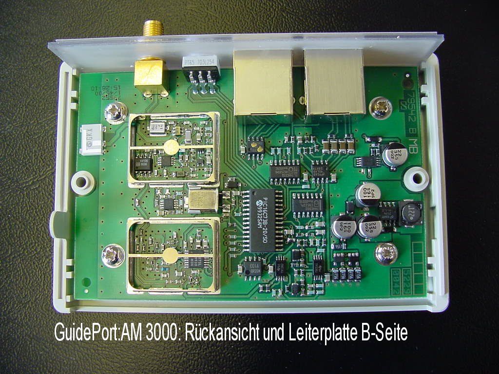
CETECOM ICT Services GmbH Test report nr..: 2_2131-C/00Issue Date: 21.12.2000Page 36 (43) AM 3000 PHOTOGRAPHS OF THE EQUIPMENT Photograph no.: 1 CETECOM ICT Services GmbH Test report nr..: 2_2131-C/00Issue Date: 21.12.2000Page 37 (43) AM 3000 PHOTOGRAPHS OF THE EQUIPMENT Photograph no.: 2 CETECOM ICT Services GmbH Test report nr..: 2_2131-C/00Issue Date: 21.12.2000Page 38 (43) AM 3000 PHOTOGRAPHS OF THE EQUIPMENT Photograph no.: 3 CETECOM ICT Services GmbH Test report nr..: 2_2131-C/00Issue Date: 21.12.2000Page 39 (43) AM 3000 PHOTOGRAPHS OF THE EQUIPMENT Photograph no.: 4 CETECOM ICT Services GmbH Test report nr..: 2_2131-C/00Issue Date: 21.12.2000Page 40 (43) AD 3000 (external antenna) PHOTOGRAPHS OF THE EQUIPMENT Photograph no.: 5 CETECOM ICT Services GmbH Test report nr..: 2_2131-C/00Issue Date: 21.12.2000Page 41 (43) AD 3000 (external antenna) PHOTOGRAPHS OF THE EQUIPMENT Photograph no.: 6 CETECOM ICT Services GmbH Test report nr..: 2_2131-C/00Issue Date: 21.12.2000Page 42 (43) AD 3000 (external antenna) PHOTOGRAPHS OF THE EQUIPMENT Photograph no.: 7
Operational Description
System Overview: This system is designed to provide individual control for audio messages pertaining to a specific display in various exhibit situations such as museums and other exibitions visited by the public. By utilizing a small inductive loop transmitter, an individual remote active antenna in front if the specific exhibit is activated enabling the visitor to hear a specific message relayed from a central control unit via cable to the remote active antenna. Approximately 94 individual channels are available allowing each remote active antenna to operate individually without interfering with …
Text truncated - open the document above for the full version.
Contact Information
Applicant
Michael Lieske
Technical Contact
TRP/Cetecom bvbaPhillip Inglis
[email protected]410-531-3439
14085 Howard Rd · Dayton, Maryland · United States
Non-Technical Contact
TRP/Cetecom bvbaPhillip Ingis
[email protected]410 531 3439
Test Firm
Cetecom ICT Services GmbHRalf Hoehn
Technical Specifications
| # | Rule Parts | Frequency Range | Power Output |
|---|---|---|---|
| 1 | 15C | 2.40 GHz - 2.48 GHz | - |
Other Applications from Sennheiser Electronic Corp
DMOSKM1G4
Aug 19, 2026Handheld Transmitter
Equipment Class
TLD - Licensed LPAS DeviceDMOSKMUHF
May 20, 2026Antenna Transceiver
Equipment Class
DWM - Part 15 Wireless Microphone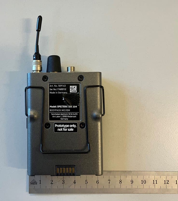
DMOSEK1G4
Mar 11, 2026Bodypack Mic/IEM
Equipment Class
TLD - Licensed LPAS Device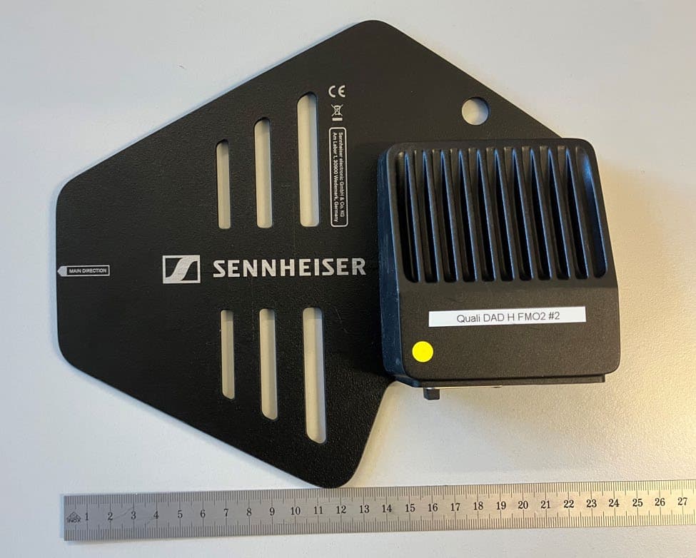
DMODAD1G4
Mar 11, 2026Antenna Transceiver
Equipment Class
TLD - Licensed LPAS DeviceDMOTSEWDX
Jan 30, 2024Wireless Table Stand
Equipment Class
TLD - Licensed LPAS Device