DMOBD10URD
Sennheiser Electronic Corp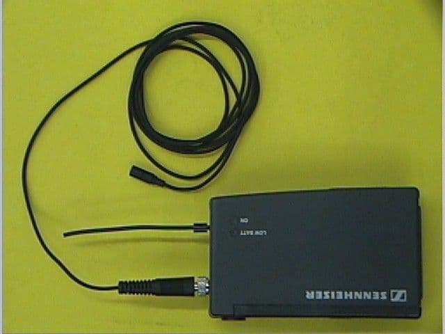
Click to zoom
Application Details
- Equipment Class
- DXX - Part 15 Low Power Communication Device Transmitter
- Date of Grant
- Aug 08, 1999
- Application Purpose
- Original Equipment
- Date of Application
- Jun 10, 1999
- Frequency Range
- 905.00000000 - 925.00000000
- Company
- Sennheiser Electronic Corp
- Country
- United States
Documents & Files
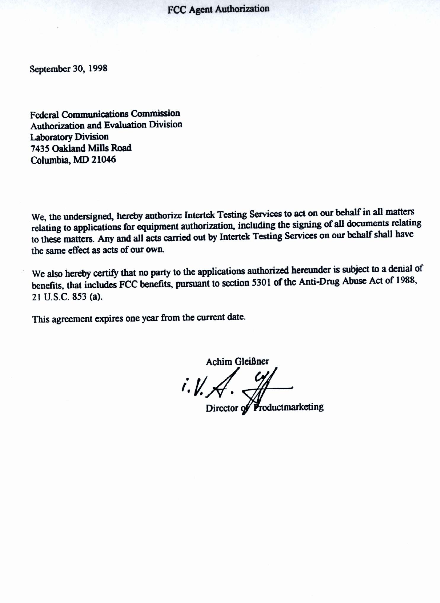
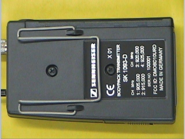
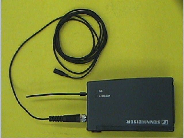
Document Text
Text extracted from the exhibit documents filed with the FCC. Open a document above to read the original.
Users Manual
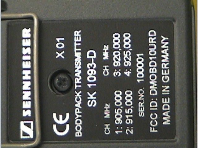
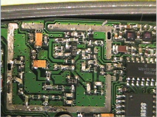
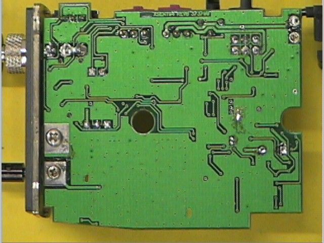
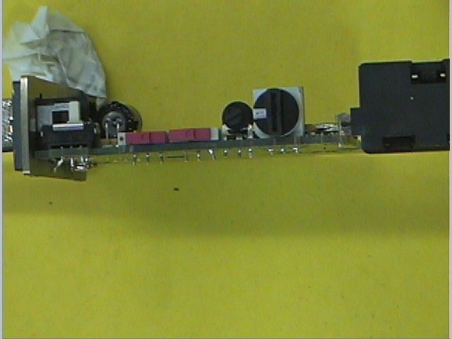
BEDIENUNGSANLEITUNG INSTRUCTIONS FOR USE NOTICES D’EMPLOI ISTRUZIONI PER L’USO INSTRUCCIONES PARA EL USO GEBRUIKSAANWIJZING DIGITAL 1000 Overall System Transmission Format:Sennheiser proprietary digital audio transmission Frequency Response:20 Hz - 15 kHz Audio Dynamic Range:Greater than 120 dB Distortion:0.2% THD RF Carrier Frequency:Ch1 (905 MHz), Ch2 (915 MHz), Ch3 (920 MHz), Ch4 (925 MHz) Number of Selectable Frequencies:Four RF Output Power:0.5 mW Transmission Range:280 feet line-of-sight, 80 to 130 feet adverse conditions FCC Approval:Part 15 approved, no user-license required Transmitter A/D Conversion:16-bit Linear, 64 times over sampling Input Impedance:1M Ohm Connectors:1/4" Unbalanced Or Miniature XLR / XH904 (none) Internal Shielding:Two ‘Aluminized’ chambers yield 90dB rejection Controls:Power On/Off, Channel Select Dimensions: Battery Life:Switching power supply, 5 hours (1x 9V alkaline) Weight:8.4 oz. (with batterie installed) Receiver D/A Conversion:16-bit Linear Output:+/- 3.5V (Unbalanced: 1.6k Ohm, Balanced: 150k) Connectors:Transformerless Balanced XLR , 1/4" Unbalanced Internal Shielding:25 ‘Aluminized’ chambers yield 90dB rejection LED Display:Battery Life, Data Received, Channel Number, Audio dB Meter Controls:Power On/Off, Channel Select Dimensions: Power Requirements:12 VDC Multi-system Operation Up to four systems can operate simultaneously. In situations where it is necessary to have more than one person wireless, each transmitter and receiver combination must be set to the same channel. Set the first system to transmit and receive on channel “one”, the second system to transmit and receive on channel “two”... and so on. Battery Life Information Alkaline batteries should last about 11 hours, NiCad rechargeable batteries will only last about 6 hours. Standard batteries may only last 3 to 6 hours. THE BATTERY HOUR DISPLAY WILL ONLY BE ACCURATE FOR ALKALINE BATTERIES. The battery life is calculated inside the transmitter and sent to the receiver and then displayed on the LCD in 1 hour incre-ments. Upon power up the battery info will take 1-5 minutes to stabilize, the battery gauge is accurate within + or - 20 min. Within the one hour mark, LO BATT will be displayed informing you that the batteries currently installed in the transmitter are nearly depleted. You may use batteries until they are completely drained without affecting the performance of the unit in any way. this divice complies with part 15 of the FCC rules. Operation is subject to the following two conditions: 1 This device may not cause harmful interference, and 2 this device must accept any interference that ́may cause undesired operation.
Block Diagram
Date: June 14, 1999 Sheet 1 of 1 Size Document Number REV BA SENNHEISER LOW PASS 1.2GHZ905-925 MHZLOW PASS 1MHZ DIGITAL DATA U? AMP PROGRAM LINES PLL
Operational Description
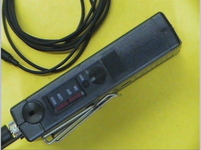
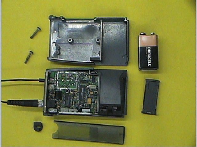
Theory of operation: The DIGITAL 1000 transmitter takes an analog audio input from a microphone. The signal is then converted to digital information and put into an information packet via a microprocessor. The data is then transmitted on a carrier frequency in the 902-928 MHZ ISM band using FSK. The transmission baud rate is 1mhz and the 4 different transmission frequencies are 905,915,920,925 MHZ. Maximum RF output power is .5mw.
Schematics
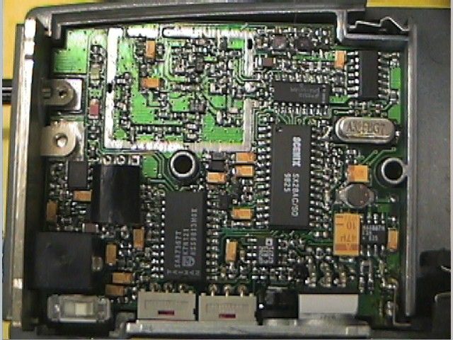
Date: June 14, 1999 Sheet 1 of 1 Size Document Number REV DA Title SK1093D SENNHEISER ANT1 ANTENNA R19 10 C44 3.3pf C23 1.8pf C24 3.3pf C8 3.3pf C25 4.7pf C26 4.7pf C15 100pf R3 9.1k R4 3k C30 6.8uf Q2 ne85633 L8 8.2nh L5 6.8nh L13 4.7nh C101 1.8pf L12 22nh R15 4.7k R14 240 C40 .1uf C43 .1uf L4 6.8nh L6 6.8nh R18 43k VCC D3 1104 R16 10k R10 51 R21 470 R22 27k R20 47 R77 18 R79 18 R6 15k C35 2.7nf C36 1nf C18 5.6pf C32 3.9pf C7 100pf C100 3.3pf C29 6.8uf C6 .1uf 1 T7 TEST POINT Q1 ne85633 C20 100pf C22 3.3pf L1 15nh L2 68nh L3 10nh L7 5.6nh R78 180 L9 6800nh VCC Q5 3906 C45 3.3nf C46 4.7nf C81 .1uf C37 390pf R9 51 L10 8200nh R68 510 R69 1k R66 51k R67 51k TP2 D7 d71 1 2 3 U1 DUAL CDS D1 353 R81 150 R2 10k R23 1k C1 .1uf C9 .1uf 1 T2 TEST POINT 1 T3 TEST POINT 3 2 1 8 4 U4A OP262 C73 120pf R1 10k 5 6 7 8 4 U4B OP262 SO8 R5 43k VCC VCC 5 6 7 8 4 U3B MC33078 3 2 1 8 4 U3A MC33078 R29 220k C98 120pf C48 6.8uf C51 6.8uf C2 .1uf C3 .1uf C31 1uf R60 1k R92 10k R7 10k R27 5.1k R28 5.1k R30 2.4k -VA VCC VCC C67 220pf S3 SW SPDT SFOR 1 STDB 2 OVLD 3 CKIN 4 VDDD 5 VSSD 6 SDO 7 SWS 8 SCK 9 TEST1 10 HPEN 11 TESTB 12 SLAVE 24 VDDA 23 VREFL 22 BIL 21 BOL 20 VDACP 19 VDACN 18 BOR 17 BIR 16 VREFR 15 IREF 14 VSSA 13 U7 SA7367 R35 4.7 R45 4.7 R44 33k R31 330 R32 330 R84 560k C49 6.8uf C47 6.8uf C50 6.8uf C52 6.8uf C53 6.8uf 1 T9 TEST POINT C61 .1uf C66 .1uf C65 .1uf C64 .1uf C62 .1uf C63 .1uf R33 2.4k VCC VCC C60 220pf VCC 2 GND 4 RA0 6 RA1 7 RA2 8 RA3 9 RB0 10 RB1 11 RB2 12 RB3 13 RB4 14 RB5 15 RB6 16 RB7 17 MCLR 28 RTCC 1 OSC1 27 OSC2 26 RC0 18 RC1 19 RC2 20 RC3 21 RC4 22 RC5 23 RC6 24 RC7 25 U5 SX28 D 2 CLK 3 Q 5 Q 6 P R 4 C L 1 U6A 74HC74 D 12 CLK 11 Q 9 Q 8 P R 1 0 C L 1 3 U6B 74HC74 R93 10k R54 1k R39 1k R55 1k R56 220k R58 33k R94 330k D2 POWER LED C90 .1uf 1 T13 TEST POINT 1 T14 TEST POINT 1 T15 TEST POINT R80 1.2m C99 33pf Y1 CRYSTAL R46 1.2m C72 .1uf C69 .1uf C10 3.3pf C11 3.3pf VCC VCC VCC OSCIN 1 OSCOUT 2 VP 3 VCC 4 D0 5 GND 6 LD 7 FIN 8 CLK 9 DATA 10 LE 11 FC 12 NC 13 FOUT 14 OP 15 OR 16 U2 lmx1501 C84 10pf C13 100pf C12 100pf C28 6.8uf C4 .1uf C5 .1uf C39 22uf VCC R82 1k D8 BATT LED R57 220k S2 SW SPDT 1 2 3 4 5 6 J2 CON6 R70 100k R76 100k VCC R83 10 S1 SW SPDT C55 6.8uf C57 6.8uf 1 T10 TEST POINT D4 MBR0520 D5 MBR0520 1 T12 TEST POINT C91 .1uf C71 .1uf R74 220k R63 100k R52 220k -VA VB+ -VAA R88 15k R90 1.5k R86 1.2m Q7 BC807 Q6 BC850B J3 PHONEJACK C74 1uf C97 6.8uf C96 6.8uf 1 T5 TEST POINT 1 T4 TEST POINT C95 10pf R87 100k R91 100k VC9 -VAA VCC C78 6.8uf C76 1nf SHDN 1 FB 2 REF 3 VL 4 SYNC 6 LX 7 V+ 8 U8 MAX887 D6 MBR0520 L11 33uh C77 47uf C80 22uf 1 T11 TEST POINT C75 .33uf C70 .1uf R65 43k R50 2.4k R41 100k R64 130k C102 1nf C79 1nf VCC D9 MBR0520 D10 MBR0520 R85 10 C93 6.8uf C92 6.8uf C94 .1uf VC9 VCC
Test Report
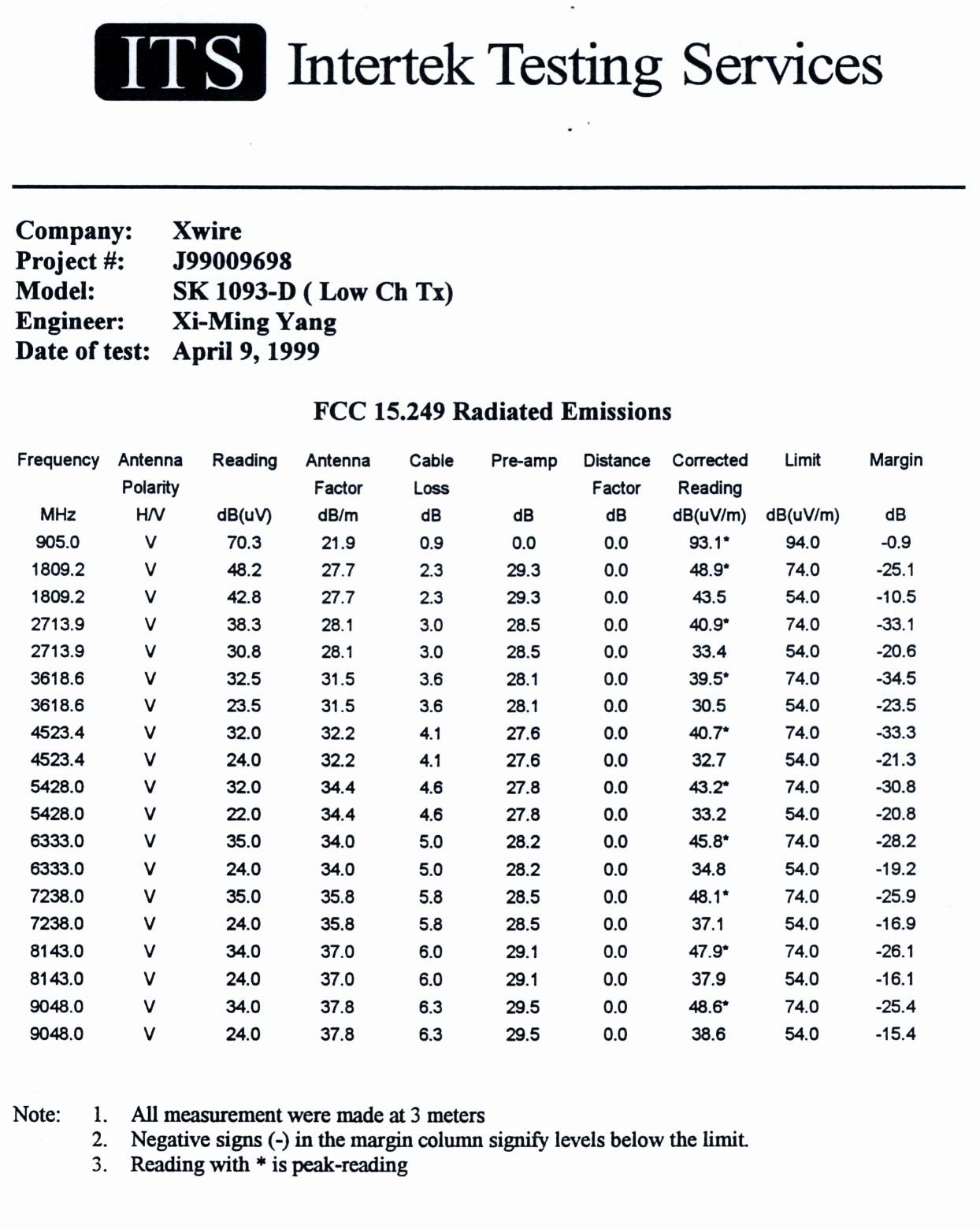
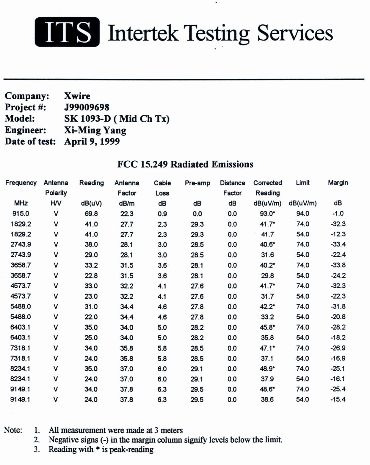
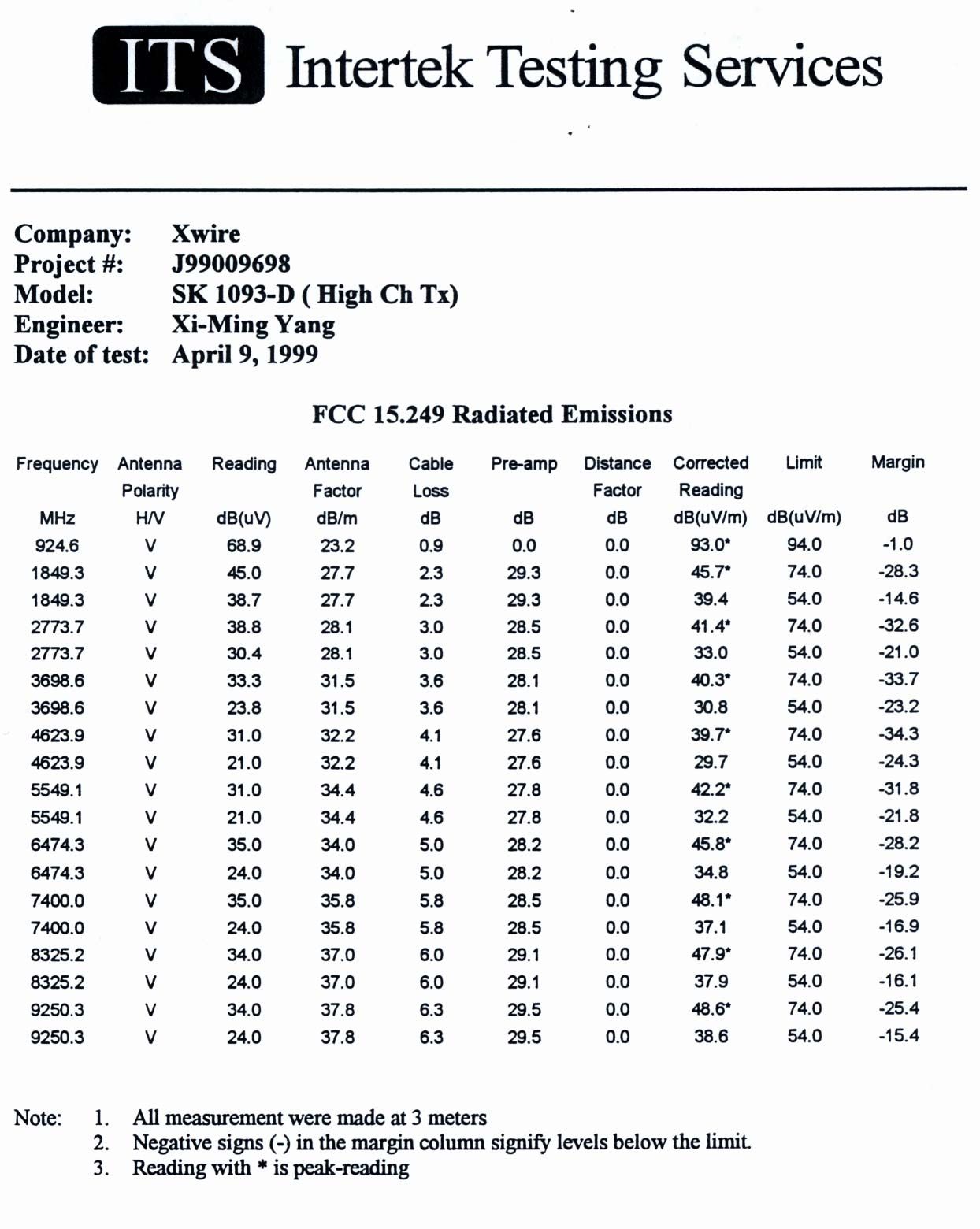
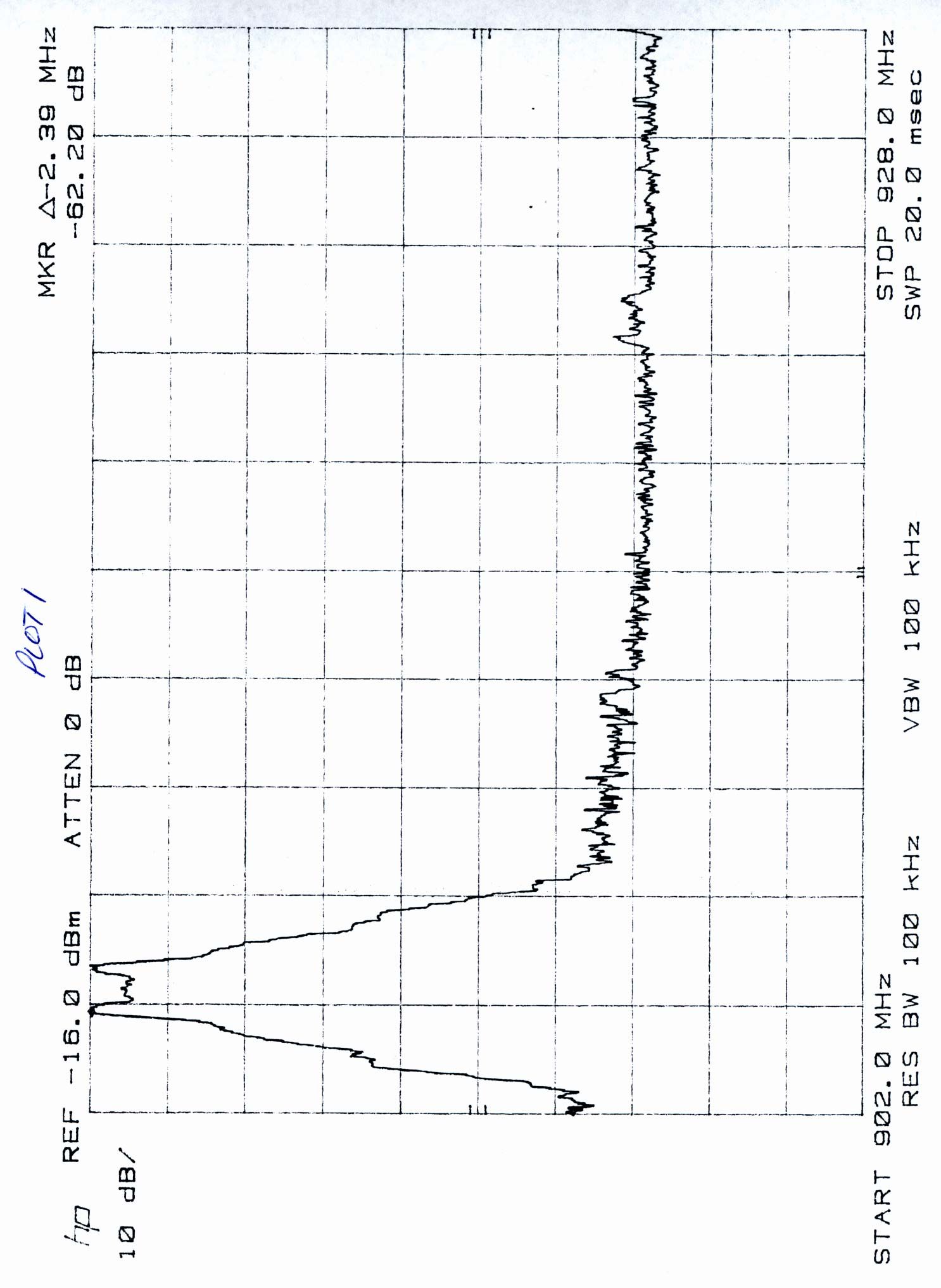
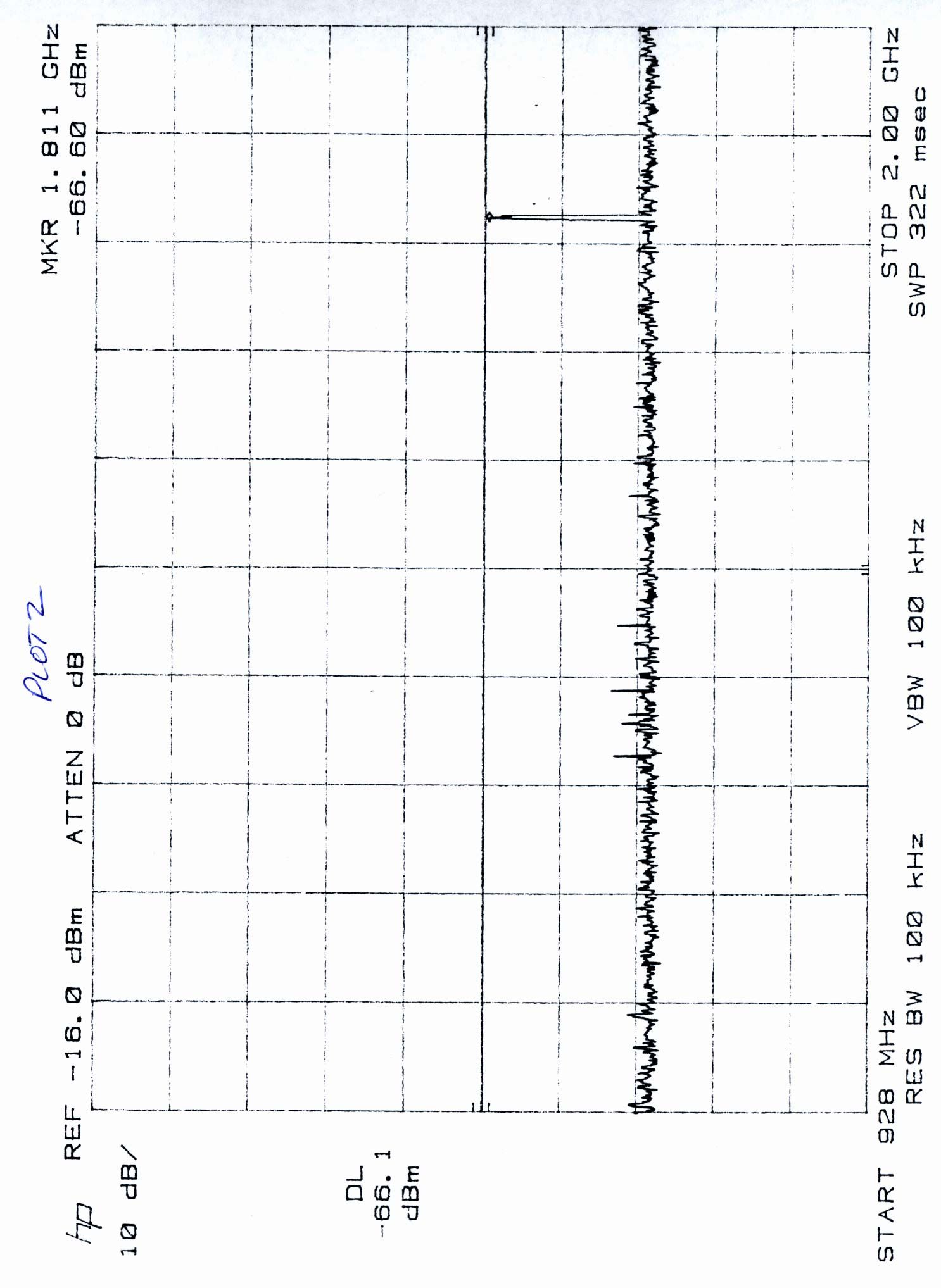
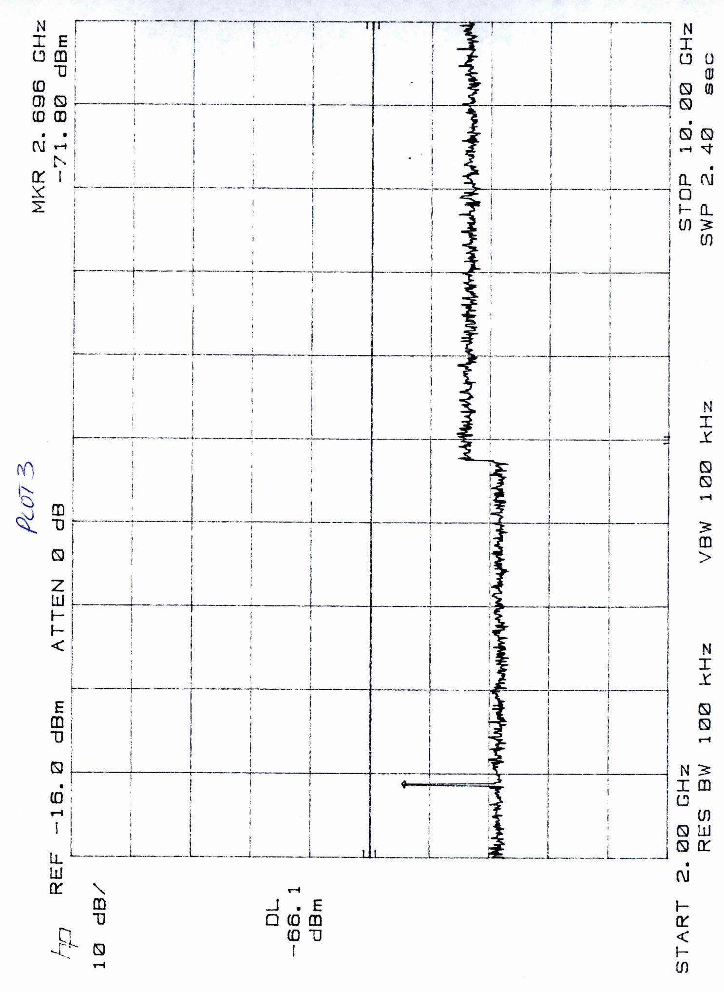
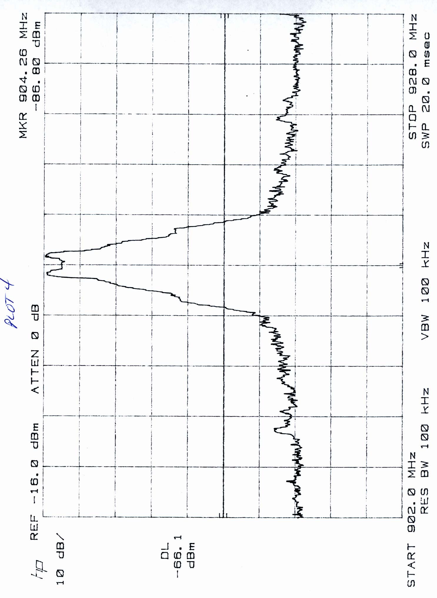
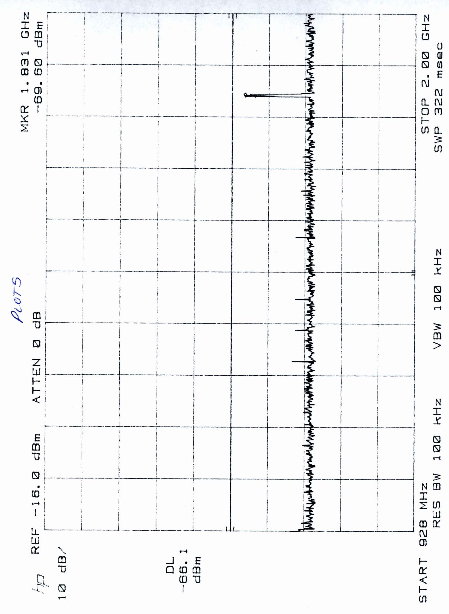
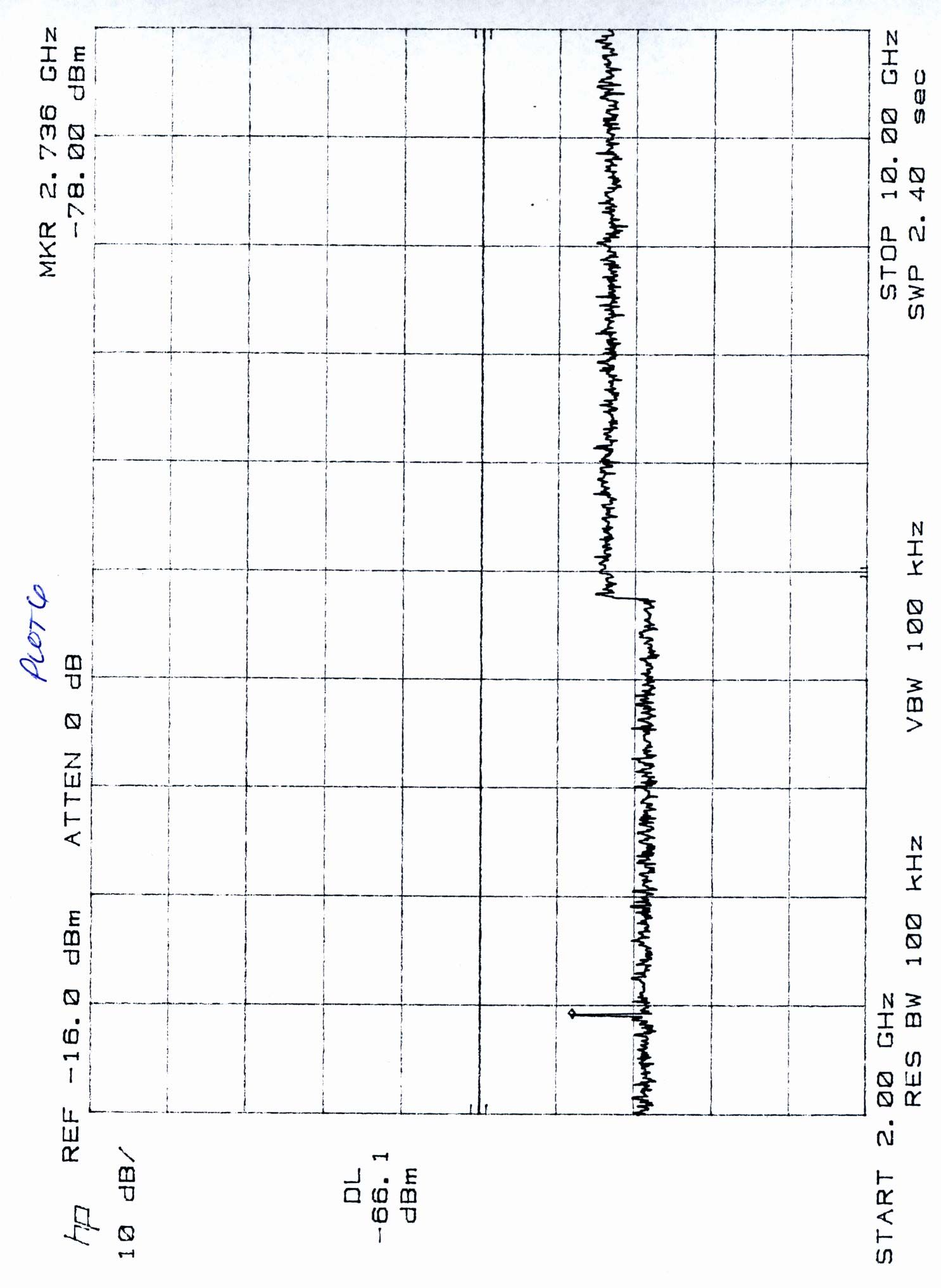
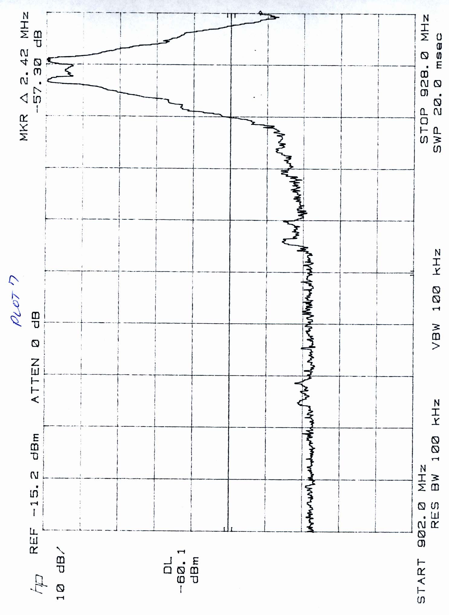
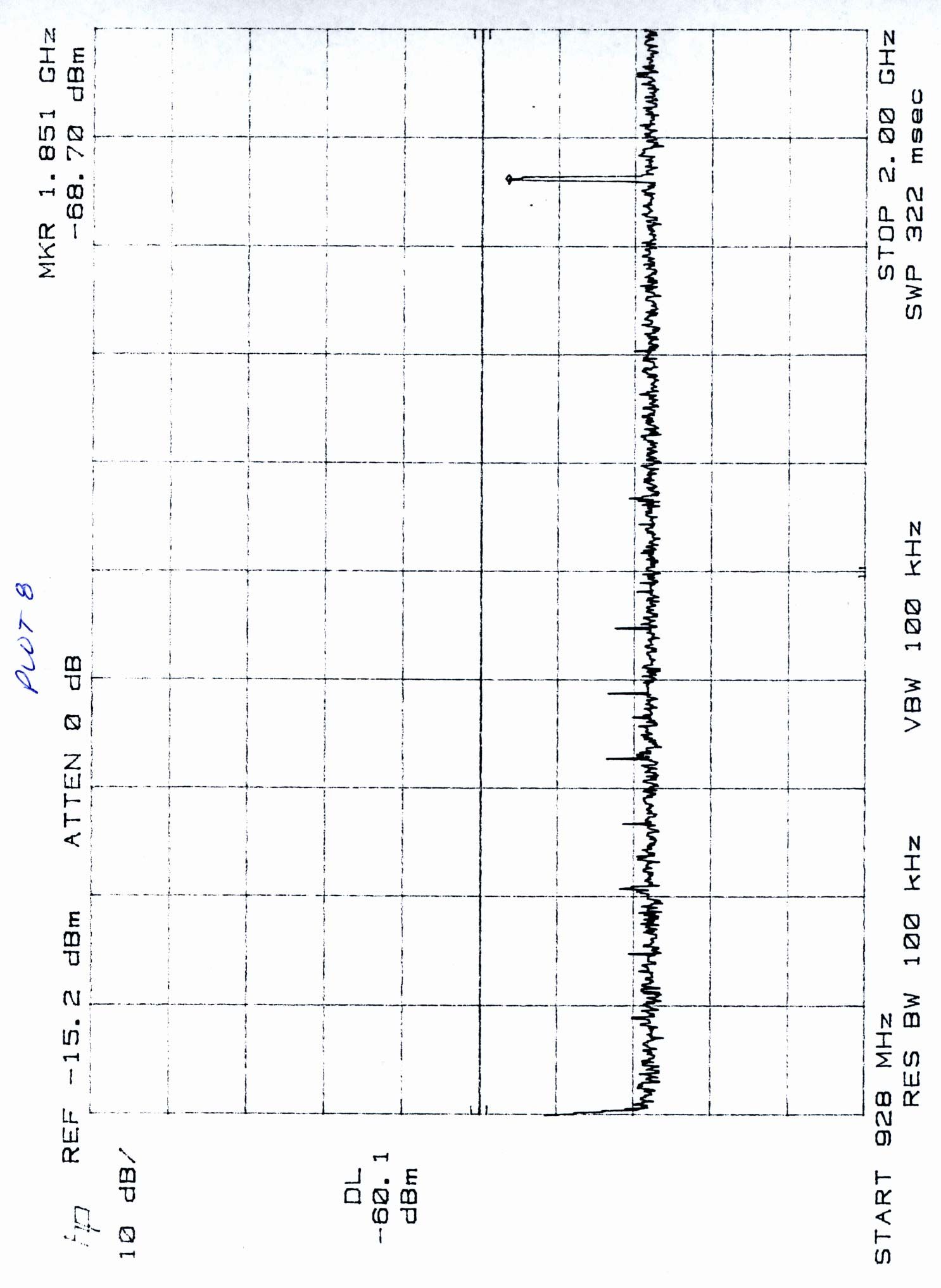
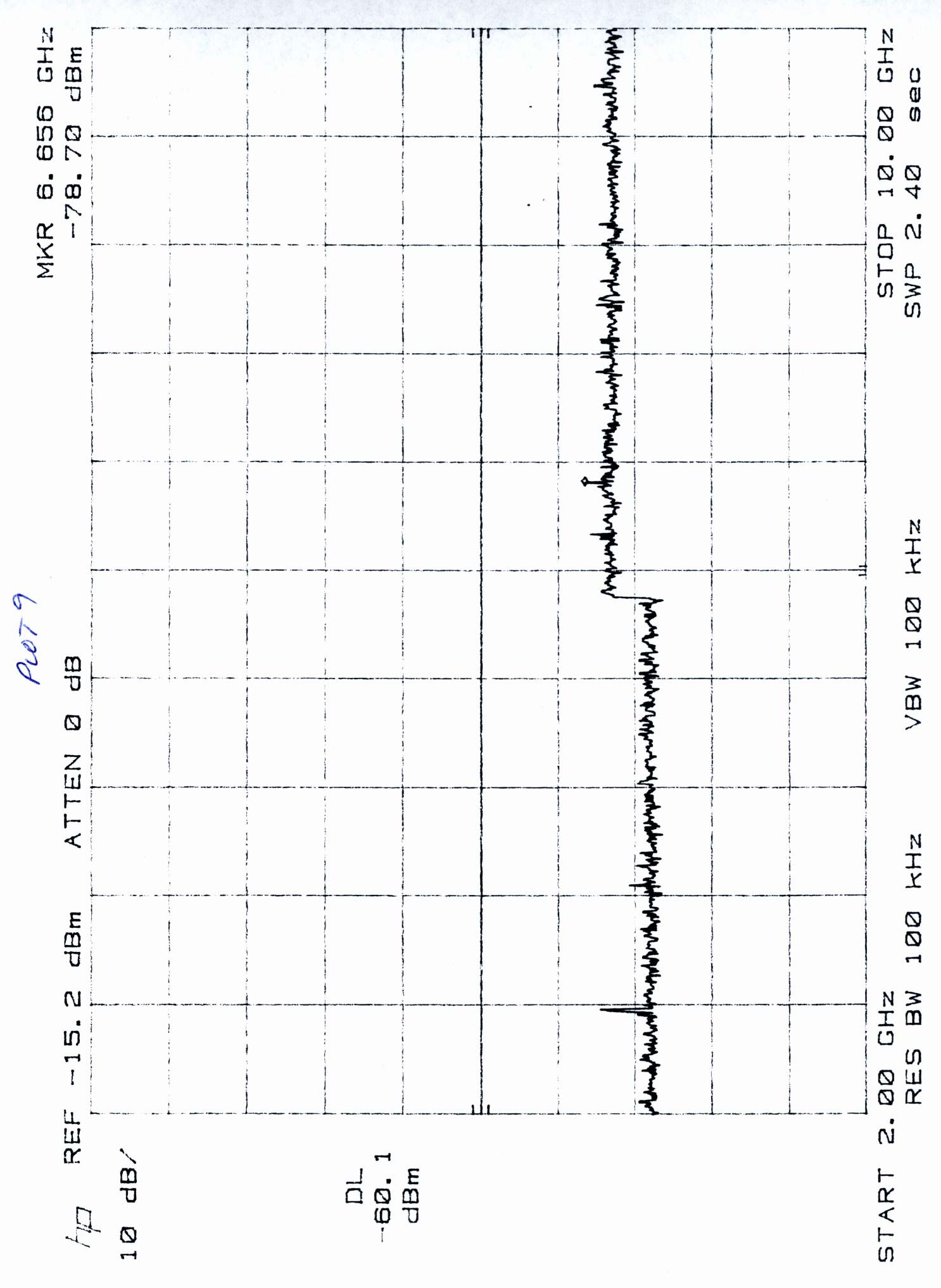
Report # J99009698 FCC Part 15.249 Certification i A APPLICATION FOR FCC CERTIFICATION Sennheiser Electronic Corp Digital 1000 Microphone Transmitter Model: Digital 1000 FCC ID: DMOBD10URD Report # J99009698 Number of Pages: 14 + data pages Date of Report: April 19, 1999 This report shall not be reproduced except in full, without written approval of Intertek Testing Services. This report must not be used to claim product endorsement by NVLAP or any agency of the U.S. Government. The results contained in this report were derived from measurements performed on the identified test samples. Any implied performance of other samples on this report is dependent on the representative of the samples tested. FCC Part 15.249 Tx Cert, Ver 5/97 k:\..\fcc\15249.cer Intertek Testing Services 1365 Adams Court, Menlo Park, CA 94025 Sennheiser Electronic Corp., SK 1093-DDate of Test: April 9, 1999 FCC ID: DMOBD10URD Report # J99009698 FCC Part 15.249 Certification ii Table of Contents 0.0 Summary of Test Results ........................................ 1 1.0 General Description ........................................... 2 1.1Product Description ....................................... 2 1.2Related Submittal(s) Grants .................................. 3 1.3Test Methodology ........................................ 3 1.4Test Facility ............................................ 3 2.0 System Test Configuration ....................................... 4 2.1Justification ............................................ 4 2.2EUT Exercising Software ................................... 4 2.3System Test Configuration ................................... 5 2.3.1 Support Equipment ................................... 5 2.3.2Block Diagram of Test Setup ............................ 5 2.4Equipment Modification .................................... 6 2.5Additions, deviations and exclusions from standards .................. 6 3.0 Emission Results .............................................. 7 3.1Field Strength Calculation ................................... 8 3.3Radiated Emission Data ..................................... 9 3.4Radiated Emissions Configuration Photograph ..................... 10 3.5Conducted Emission Data .................................. 11 4.0 Out of Band Emission Plot ...................................... 12 5.0 Antenna Requirement ......................................... 13 6.0 List of Exhibits ............................................. 14 Intertek Testing Services 1365 Adams Court, Menlo Park, CA 94025 Sennheiser Electronic Corp., SK 1093-DDate of Test: April 9, 1999 FCC ID: DMOBD10URD Report # J99009698 FCC Part 15.249 Certification 1 0.0 Summary of Test Results Sennheiser - MODEL: SK 1093-D FCC ID: DMOBD10URD TESTREFERENCERESULTS Radiated Emission15.249Complies Conducted Emission15.207Not Applicable (See Section 3.5) Antenna Requirement15.203Complies Test Engineer: Date: 6/1/99 Xi-Ming Yang Site Manager: Date: 6/1/99 David Chernomordik Intertek Testing Services 1365 Adams Court, Menlo Park, CA 94025 Sennheiser Electronic Corp., SK 1093-DDate of Test: April 9, 1999 FCC ID: DMOBD10URD Report # J99009698 FCC Part 15.249 Certification 2 1.0 General Description 1.1Product Description The EUT is a wireless microphone transmitter. Please refer to the attached technical description for details. Intertek Testing Services 1365 Adams Court, Menlo Park, CA 94025 Sennheiser Electronic Corp., SK 1093-DDate of Test: April 9, 1999 FCC ID: DMOBD10URD Report # J99009698 FCC Part 15.249 Certification 3 1.2Related Submittal(s) Grants This is an Application for Certification of a low power transmitter. One transmitter is included in this Application. This specific report details the emission characteristics of transmitter. The FCC ID for the receiver associated with this transmitter is DMOBD10URD. The receivers are subject to the DoC process. 1.3Test Methodology Both AC mains line-conducted and radiated emission measurements were performed according to the procedures in ANSI C63.4 (1992). All measurements were performed in Open Area Test Sites. Preliminary scans were performed in the Open Area Test Sites only to determine worst case modes. For each scan, the procedure for maximizing emissions in Appendices D and E were followed. All Radiated tests were performed at an antenna to EUT distance of 3 meters, unless stated otherwise in the " Justification Section " of this Application. 1.4Test Facility The open area test site and conducted measurement facility used to collect the radiated data is Site 1 . This test facility and site measurement data have been fully placed on file with the FCC and NVLAP accredited. Intertek Testing Services 1365 Adams Court, Menlo Park, CA 94025 Sennheiser Electronic Corp., SK 1093-DDate of Test: April 9, 1999 FCC ID: DMOBD10URD Report # J99009698 FCC Part 15.249 Certification 4 2.0 System Test Configuration 2.1Justification For emission testing, the equipment under test (EUT) was configured for testing in a typical fashion (as a customer would normally use it). During testing, all cables were manipulated to produce worst case emissions. For the measurements, the EUT is attached to a cardboard box (if necessary) and placed on the wooden turntable. If the EUT attaches to peripherals, they are connected and operational (as typical as possible). The EUT is wired to transmit full power. The signal is maximized through rotation and placement in the three orthogonal axes. The antenna height and polarization are varied during the search for maximum signal level. The antenna height is varied from 1 to 4 meters. Radiated emissions are taken at three meters unless the signal level is too low for measurement at that distance. If necessary, a pre-amplifier is used and/or the test is conducted at a closer distance. All readings are extrapolated back to the equivalent three meter reading using inverse scaling with distance. 2.2EUT Exercising Software The EUT exercise program used during radiated and condu…
Text truncated - open the document above for the full version.
Contact Information
Applicant
Michael Lieske
Technical Contact
Intertek Testing ServicesDavid Chernomordik
[email protected]650/463-2900
1365 Adams Ct. · Menlo Park, California · United States
Non-Technical Contact
X WireGuy Coker
916/929-9473
Test Firm
Intertek Testing Services NA Inc.John Quigley
Technical Specifications
| # | Rule Parts | Frequency Range | Power Output |
|---|---|---|---|
| 1 | 15C | 905 MHz - 925 MHz | - |
Other Applications from Sennheiser Electronic Corp
DMOSKM1G4
Aug 19, 2026Handheld Transmitter
Equipment Class
TLD - Licensed LPAS DeviceDMOSKMUHF
May 20, 2026Antenna Transceiver
Equipment Class
DWM - Part 15 Wireless Microphone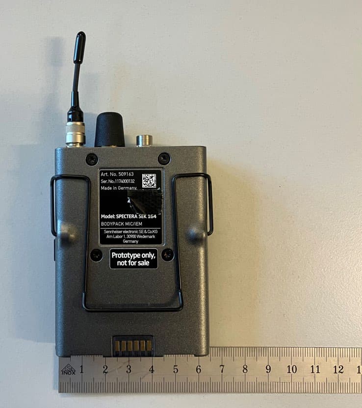
DMOSEK1G4
Mar 11, 2026Bodypack Mic/IEM
Equipment Class
TLD - Licensed LPAS Device
DMODAD1G4
Mar 11, 2026Antenna Transceiver
Equipment Class
TLD - Licensed LPAS DeviceDMOTSEWDX
Jan 30, 2024Wireless Table Stand
Equipment Class
TLD - Licensed LPAS Device