DMOG3SKP300Microphone plug-on transmitter
Sennheiser Electronic Corp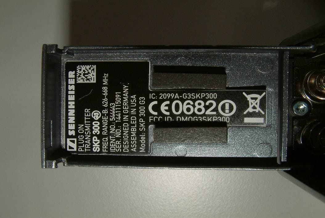
Click to zoom
Application Details
- Equipment Class
- TNB - Licensed Non-Broadcast Station Transmitter
- Date of Grant
- Feb 21, 2012
- Application Purpose
- Original Equipment
- Date of Application
- Feb 21, 2012
- Equipment Note
- Microphone plug-on transmitter
- Frequency Range
- 626.00000000 - 668.00000000
- Company
- Sennheiser Electronic Corp
- Country
- United States
Documents & Files
Document Text
Text extracted from the exhibit documents filed with the FCC. Open a document above to read the original.
Users Manual
SKP 300 Instruction manual SKP 300 G3 | 1 Contents Contents Important safety instructions ............................................2 The SKP 300 G3 plug-on transmitter................................3 Areas of application .......................................................3 The frequency bank system .........................................4 Delivery includes ...................................................................5 Product overview ..................................................................6 Overview of the SKP 300 G3 plug-on transmitter.......................................................................6 Overview of the displays ...............................................7 Putting the plug-on transmitter into operation.............8 Inserting the batteries/accupack ................................8 Charging the accupack...................................................8 Plugging the plug-on transmitter onto a microphone ......................................................................9 Using the plug-on transmitter ........................................ 10 Switching the plug-on transmitter on/off ............. 10 Deactivating the lock mode temporarily ................ 11 Muting the audio signal or deactivating the RF signal ................................................................. 12 Selecting a standard display ..................................... 13 Using the operating menu ............................................... 14 The buttons................................................................... 14 Overview of the operating menu.............................. 14 Working with the operating menu .......................... 15 Adjusting settings via the operating menu ................. 17 he main menu “Menu” ............................................... 17 The extended menu “Advanced Menu” .................. 19 Synchronizing the plug-on transmitter with a receiver ............................................................................. 23 Synchronizing the plug-on transmitter with the receiver – individual operation .......................... 23 Synchronizing plug-on transmitters with receivers – multi-channel operation ........................ 24 Cleaning and maintaining the plug-on transmitter.... 25 Recommendations and tips ............................................. 26 If a problem occurs ... ........................................................ 27 Specifications...................................................................... 29 Manufacturer Declarations .............................................. 31 2 | SKP 300 G3 Important safety instructions Important safety instructions •Read this instruction manual. •Keep this instruction manual. Always include this instruction manual when passing the product on to third parties. •Heed all warnings and follow all instructions. •Use only a cloth for cleaning the product. •Do not place the product near any heat sources such as radiators, stoves, or other devices (including amplifiers) that produce heat. •Only use attachments/accessories specified by Sennheiser. •Refer all servicing to qualified service personnel. Servicing is required if the device has been damaged in any way, liquid has been spilled, objects have fallen inside, the product has been exposed to rain or moisture, does not operate properly or has been dropped. •WARNING: To reduce the risk of short circuits, do not use the product near water and do not expose it to rain or moisture. Intended use Intended use of the SKP 300 G3 plug-on transmitter includes: •having read this instruction manual, especially the chapter “Important safety instructions” above on this page, •using the product within the operating conditions and limitations described in this instruction manual. “Improper use” means using the product other than as described in these instructions, or under operating conditions which differ from those described herein. SKP 300 G3 | 3 The SKP 300 G3 plug-on transmitter The SKP 300 G3 plug-on transmitter The SKP 300 G3 plug-on transmitter is part of the evolu- tion wireless series ew 300 G3. This series offers high- quality state-of-the-art RF transmission systems with a high level of operational reliability and ease of use. Transmitters and receivers permit wireless transmission with studio-quality sound. Features of the SKP 300 G3 plug-on transmitter: •Optimized PLL synthesizer and microprocessor technology •HDX noise reduction system •Pilot tone squelch control •Switching bandwidth of up to 42 MHz •Increased immunity to intermodulation and inter- ferences in multi-channel operation •48 V phantom powering Areas of application The plug-on transmitter can be combined with the EM 300 G3 rack-mount receiver. The EM 300 G3 rack- mount receiver is available in the same UHF frequency ranges and is equipped with the same frequency bank system with factory-preset frequencies. This has the advantage that: •a transmission system is ready for immediate use after switch-on, •several transmission systems can be operated simultaneously on the preset frequencies without causing intermodulation interference. Transmitter Combinable with ... Receiver SKP 300 G3dynamic and condenser microphones. We recom- mend using Sennheiser microphones. EM 300 G3 Transmitter and receiver must have at least software version 1.7 (see page 23). 531.375 ew300 G3 B.Ch: 20.24 PEAK EQ: + 12dB P -10 040 30 20 10 -20 -30 -40 AF RF MHz SKP300 4 | SKP 300 G3 The SKP 300 G3 plug-on transmitter The frequency bank system The plug-on transmitter is available in 7 UHF frequency ranges with up to 1,680 transmission frequencies per frequency range: Each frequency range (A-E, G, GB) offers 26 frequency banks with up to 24 channels each: Each of the channels in the frequency banks “1” to “20” has been factory-preset to a fixed transmission frequency (frequency preset). The factory-preset frequencies within one frequency bank are intermodu- lation-free. These …
Text truncated - open the document above for the full version.
Cover Letter(s)
CONFIDENTIALITY REQUEST Federal Communication Commission Equipment Authorization Division, Application Processing Branch 7435 Oakland Mills Road Columbia, MD 21048 February 15, 2012 TO WHOM IT MAY CONCERN Pursuant to Paragraphs §0.457 and 0.459 of the Commission’s Rules (47 C.F.R.) and Section §552(b)(4) of the Freedom of Information Act, Company requests confidentiality for the following products: FCC ID Number Product Title/Model DMOG3SKP300 SKP 300 G3 For the product stated above, we request that the following information be held confidential: 1. Circuit diagrams, BOM, and PCBs submitted as Equipment Authorization Electronic Filing attachment: "schematics”. 2. Block diagram submitted as Equipment Authorization Electronic Filing attachment: “blockdiagram”. 3. Operational description submitted as Equipment Authorization Electronic Filing attachment: “operational description” 4. Tune Up Info submitted as Equipment Authorization Electronic Filing attachment: “tune up info” The above exhibits contain Company trade secrets and proprietary information that could be of benefit to our competitors regarding the design of our mobile handset. This material is not customarily available to the general public and we request that it be withheld from public inspection. If you have any questions, please feel free to contact me at the address shown below. Sincerely, Name: Volker Bartsch Company: Sennheiser electronic Address: Am Labor 1 D-30900 Wedemark (Germany) Phone: 49-5130-600-465 Email: [email protected]
External Photos
Test report no.: 1-3890/11-01-04-A 2012-02-22 Page 67 of 83 Annex B External photographs of the EUT Photo documentation: Photo 1: Photo 2: Test report no.: 1-3890/11-01-04-A 2012-02-22 Page 68 of 83 Photo 3: Photo 4: Test report no.: 1-3890/11-01-04-A 2012-02-22 Page 69 of 83 Photo 5: Photo 6: Test report no.: 1-3890/11-01-04-A 2012-02-22 Page 70 of 83 Photo 7: Photo 8:
Internal Photos
Test report no.: 1-3890/11-01-04-A 2012-02-22 Page 71 of 83 Annex C Internal photographs of the EUT Photo documentation: Photo 1: Photo 2: Test report no.: 1-3890/11-01-04-A 2012-02-22 Page 72 of 83 Photo 3: Photo 4: Test report no.: 1-3890/11-01-04-A 2012-02-22 Page 73 of 83 Photo 5: Photo 6: Test report no.: 1-3890/11-01-04-A 2012-02-22 Page 74 of 83 Photo 7: Photo 8: Test report no.: 1-3890/11-01-04-A 2012-02-22 Page 75 of 83 Photo 9: Photo 10: Test report no.: 1-3890/11-01-04-A 2012-02-22 Page 76 of 83 Photo 11: Photo 12: Test report no.: 1-3890/11-01-04-A 2012-02-22 Page 77 of 83 Photo 13: Photo 14: Test report no.: 1-3890/11-01-04-A 2012-02-22 Page 78 of 83 Photo 15: Photo 16: Test report no.: 1-3890/11-01-04-A 2012-02-22 Page 79 of 83 Photo 17: Photo 18: Test report no.: 1-3890/11-01-04-A 2012-02-22 Page 80 of 83 Photo 19: Photo 20: Test report no.: 1-3890/11-01-04-A 2012-02-22 Page 81 of 83 Photo 21: Photo 22:
Test Report
2012-02-22 Page 1 of 83 TEST REPORT Test report no.: 1-3890/11-01-04-A Testing laboratory Applicant CETECOM ICT Services GmbH Untertuerkheimer Strasse 6 – 10 66117 Saarbruecken / Germany Phone: + 49 681 5 98 - 0 Fax: + 49 681 5 98 - 9075 Internet: http://www.cetecom.com e-mail: [email protected] Accredited Testing Laboratory: The testing laboratory (area of testing) is accredited according to DIN EN ISO/IEC 17025 (2005) by the Deutsche Akkreditierungsstelle GmbH (DAkkS) The accreditation is valid for the scope of testing procedures as stated in the accreditation certificate with the registration number: D-PL-12076-01-01 Area of Testing: Radio/Satellite Communications Sennheiser electronic GmbH & Co. KG Am Labor 1 30900 Wedemark / GERMANY Phone: +49 5130 600-0 Fax: +49 5130 600-574 Contact: Volker Bartsch e-mail: [email protected] Phone: +49 5130 600-465 Manufacturer Sennheiser electronic GmbH & Co. KG Am Labor 1 30900 Wedemark / GERMANY Test standard/s 47 CFR Part 74 Title 47 of the Code of Federal Regulations; Chapter I Part 74 - Experimental radio, auxiliary, special broadcast and other program distribution services RSS - 123 Issue 1 Rev. 2 Spectrum Management and Telecommunications Policy - Radio Standards Specification Low Power Licensed Radiocommunication Devices For further applied test standards please refer to section 3 of this test report. Test Item Kind of test item: Plug-On Transmitter Model name: SKP 300 G3 FCC ID: DMOG3SKP300 IC: 2099A-G3SKP300 Frequency: Range-A: 516 MHz –558 MHz Range-B: 626 MHz – 668 MHz Range-G: 566 MHz – 608 MHz Technology tested: Single carrier Antenna: Integrated Antenna Power Supply: 3.00 V DC by 2 x battery Type AA Temperature Range: -30°C to +50 °C This test report is electronically signed and valid without handwriting signature. For verification of the electronic signatures, the public keys can be requested at the testing laboratory. Test report authorised: Test performed: Marco Bertolino Stefan Bös Testing Manager Senior Testing Manager Test report no.: 1-3890/11-01-04-A 2012-02-22 Page 2 of 83 1 Table of contents 1 Table of contents ..................................................................................................................................... 2 2 General information ................................................................................................................................. 3 2.1 Notes and disclaimer ..................................................................................................................... 3 2.2 Application details ......................................................................................................................... 3 3 Test standard/s ........................................................................................................................................ 3 4 Test environment ..................................................................................................................................... 4 5 Test item ................................................................................................................................................... 4 6 Test laboratories sub-contracted ............................................................................................................ 4 7 Summary of measurement results .......................................................................................................... 5 7.1 RSP100 test report cover sheet / performance test data ............................................................. 6 8 RF measurements .................................................................................................................................... 7 8.1 Description of test setup ............................................................................................................... 7 8.1.1 Radiated measurements ....................................................................................................... 7 8.1.2 Conducted measurements .................................................................................................... 8 8.2 Additional comments .................................................................................................................... 8 9 Measurement results ............................................................................................................................... 9 9.1 Output power (radiated) ................................................................................................................ 9 9.2 Frequency stability ...................................................................................................................... 10 9.2.1 Frequency error vs. temperature ......................................................................................... 10 9.2.2 Frequency error vs. voltage ................................................................................................. 15 9.3 Modulation characteristics.......................................................................................................... 19 9.4 Occupied bandwidth ................................................................................................................... 21 9.5 Unwanted radiation (spectrum mask)......................................................................................... 28 9.6 Field strength of spurious radiation. .......................................................................................... 34 9.7 Receiver spurious emissions / Transmitter Idle (radiated) ........................................................ 53 10 Test equipment and ancillaries used for tests ............................................................................... 64 11 Observations ................................................................................................................................... 65 Annex A Photographs of the test setup .....…
Text truncated - open the document above for the full version.
Test Setup Photos
Test report no.: 1-3890/11-01-04-A 2012-02-22 Page 66 of 83 Annex A Photographs of the test setup Photo documentation: Photo 1: Photo 2:
Contact Information
Applicant
Michael Lieske
Test Firm
cetecom advanced GmbHGerald Schmidt
Technical Specifications
| # | Rule Parts | Frequency Range | Power Output | Emission | Tolerance |
|---|---|---|---|---|---|
| 3 | 74 | 626 MHz - 668 MHz | 19.00 mW | 96K2F1E | 6.9 ppm |
Other Applications from Sennheiser Electronic Corp
DMOSKM1G4
Aug 19, 2026Handheld Transmitter
Equipment Class
TLD - Licensed LPAS DeviceDMOSKMUHF
May 20, 2026Antenna Transceiver
Equipment Class
DWM - Part 15 Wireless Microphone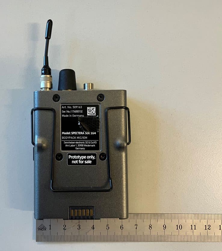
DMOSEK1G4
Mar 11, 2026Bodypack Mic/IEM
Equipment Class
TLD - Licensed LPAS Device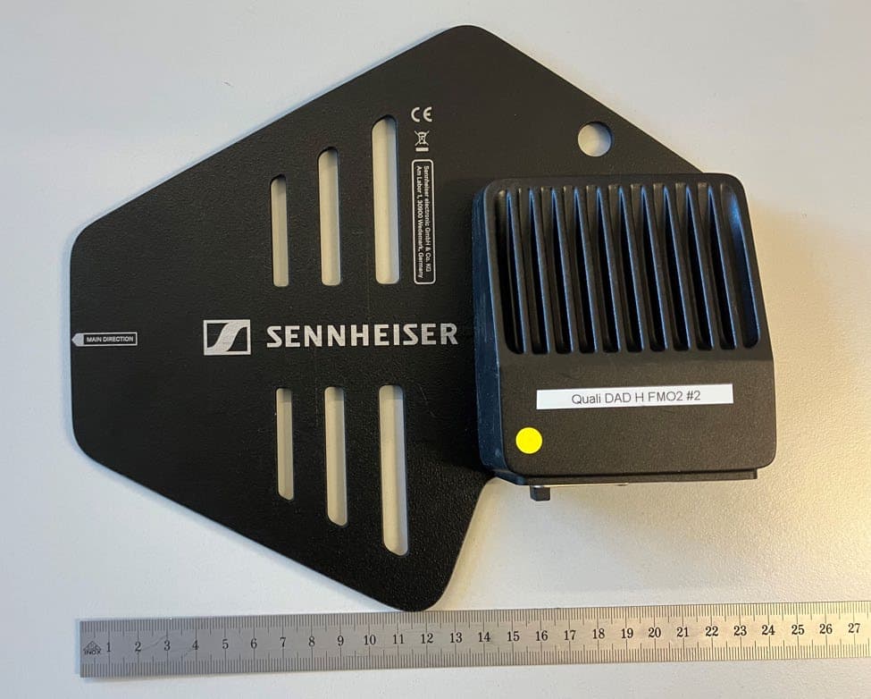
DMODAD1G4
Mar 11, 2026Antenna Transceiver
Equipment Class
TLD - Licensed LPAS DeviceDMOTSEWDX
Jan 30, 2024Wireless Table Stand
Equipment Class
TLD - Licensed LPAS Device