DMOIDGPSFAudio message activator
Sennheiser Electronic Corp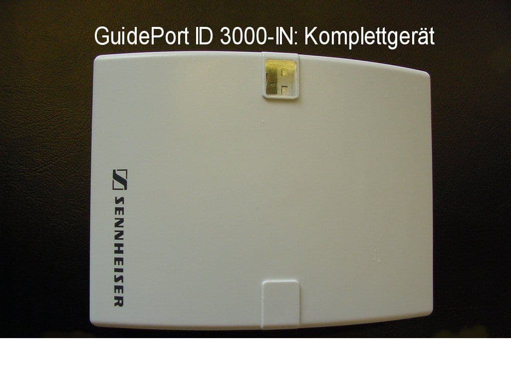
Click to zoom
Application Details
- Equipment Class
- DCD - Part 15 Low Power Transmitter Below 1705 kHz
- Date of Grant
- Apr 09, 2001
- Application Purpose
- Original Equipment
- Date of Application
- Mar 27, 2001
- Equipment Note
- Audio message activator
- Frequency Range
- 0.12700000 - 0.12700000
- Company
- Sennheiser Electronic Corp
- Country
- United States
Documents & Files
Document Text
Text extracted from the exhibit documents filed with the FCC. Open a document above to read the original.
Users Manual
GuidePortSoftware Short User Guide Version 1.0 of 27 July 2000 Sennheiser electronic GmbH&Co. KG Am Labor 1 30900Wedemark Germany GuidePort: Software Description27. Juli 2000Seite 2 Contents 1 SETTING UP THE BASE STATION HARDWARE...................................................3 2 INSTALLING THE CELL TRANSMITTER LOADER SOFTWARE.....................4 3 CENTRAL UNIT PC .......................................................................................................6 3.1 CENTRAL UNIT SOFTWARE...........................................................................6 3.2 DATABASE DRIVER...........................................................................................7 3.3 PALMTOP SOFTWARE .....................................................................................8 4 CREATING A GUIDEPORT INSTALLATION FOR YOUR EXHIBITION..........9 5ANNOUNCEMENTS.....................................................................................................18 6 DOWNLOADING THE CONFIGURATION FILES TO THE GUIDEPORT TRANSMITTERS ..........................................................................................................19 GuidePort: Software Description27. Juli 2000Seite 3 1Setting Up the Base Station Hardware •First connect all Cell Transmitters via a USB hub to a Base Station PC. •Then connect the Base Station PC to your local area network. •Via the network, the Base Stations are connected to a Central Unit PC. Cell Transmitter Cell Transmitter Cell Transmitter Cell Transmitter USB-Hub Cell Transmitter Cell Transmitter Cell Transmitter Cell Transmitter USB-Hub Base Station Base Station Base Station PC with CT Loader Base Station PC with CT Loader Cental Unit PC with: •Sound Card, capable of 32 kHz sampling rate •G7.22++ converter and announcement software •GP CU software Figure 1: SystemSet-Up N.B.: Instead of a local area network solution with separate Central Unit PC and Base Station PC, you can also work with only one PC or laptop computer with Windows 98™ and a USB connector. Via the USB, the Base Station PC detects the IDs of all Cell Transmitters connected to it, and transfers the configuration files to the Cell Transmitters. (N.B.: These configuration files will be created later with the Central Unit Software, see chapter 4) When starting the Base Station PC or hot plugging the Cell Transmitters into the PC, a Windows 98 message will inform you about the detection of a new USB device. Please insert the „USB Driver“ disk to install the missing driver. Now your hardware is ready for the installation of the Cell Transmitter Loader Software. Local Area Network GuidePort: Software Description27. Juli 2000Seite 4 2Installing the Cell Transmitter Loader Software •Insert the „Cell Transmitter Loader“ disk and run „setup.exe“ to install the Cell Transmitter Loader Software on your Base Station PC. The following screen will be shown: •Click [Next] to continue installation. •The InstallShield assistant will suggest a destination directory where to install the program files. You may either accept the proposed path or click [Browse] to choose a different path. Please make a note of the path as you will need it later for setting up the cell transmitters. GuidePort: Software Description27. Juli 2000Seite 5 Installation will then continue. The Shield assistant will close automatically when the program has been installed. •Now start the Cell Transmitter Loader program from the program directory of the Windows 98™ start menu. The following window will be displayed: •Switch on all Cell Transmitters connected to your Base Station PC. Click [Find Transmitter] to locate the transmitters. The number and IDs of all transmitters found will be displayed: Number of transmitters found Transmitter ID Buttons for selecting for a transmitter GuidePort: Software Description27. Juli 2000Seite 6 The Cell Transmitter Loader Software will create a „TXxxxxxx.ini“ file in its destination path for every transmitter it has found. These files will be used later for configuring the transmitters with the Central Unit Software. Now you have to install the Central Unit Software on your Central Unit PC. N.B.: Instead of a local area network solution with separate Central Unit PC and Base Station PC, you can also work with only one PC or laptop computer with Windows 98™ and a USB connector. 3Central Unit PC The Central Unit PC is at the heart of the GuidePort system. It serves to configure the entire GuidePort installation with its cells, transmitters, events and identifiers. 3.1 Central Unit Software •Insert the „Central Unit Software“ disk and run „setup.exe“ to install the program on your Central Unit PC. The following screen will be shown: •The InstallShield assistant will then suggest a destination directory where to install the program files. You may accept the proposed path or click [Browse] to choose a different directory. •In order to run the Central Unit Software, you now have to install the GuidePort database driver. GuidePort: Software Description27. Juli 2000Seite 7 3.2 Database Driver •Insert the first disk of „GuidePort Database Driver Ver. 3.5“ and start „Setup.exe“ to install the driver. The following window will be displayed: •Select both items and click [Next] to continue. The next window contains additional, optional data formats: •Select all formats and click [Next] to start the installation. •When the program asks for disks 2 and 3, insert the respective disk and click [OK] to continue installation. •When the installation has been completed a message will be displayed. Click [OK] to leave the InstallShield assistant. GuidePort: Software Description27. Juli 2000Seite 8 3.3 Palmtop Software To complete the configuration of your GuidePort installation, install the identifier programming software on your 3Com Palm IIIx or PalmV. •First install the Palm™ Desktop Organizer Software as described in the palmtop’s manual. •The GuidePort.prc application is contained on the „GP Palmtop Softwar…
Text truncated - open the document above for the full version.
Block Diagram
Block diagram: FCC ID:DMOIDGPSF This unit is a simple low frequency inductive loop radiator intended to emit a very low level signal at 127 kH z: Microprocessor Control Low Freque ncy Oscillator Batter y
Cover Letter(s)
System Overview: This system is designed to provide individual control for audio messages pertaining to a specific display in various exhibit situations such as museums and other exibitions visited by the public. By utilizing a small inductive loop transmitter, an individual remote active antenna in front if the specific exhibit is activated enabling the visitor to hear a specific message relayed from a central control unit via cable to the remote active antenna. Approximately 94 individual channels are available allowing each remote active antenna to operate individually without interfering with other units in nearby exhibit halls. A detailed description of the installation requirements and equipment setup is provided in the system manual which has been filed. Due to its complexity, this system is professionally installed and qualifies for exemption from the unique connector rules applicable to part 15 transmitters. A professional installation manual is currently under draft and will be provided as soon as it is available. Under current Part 15 interpretations, test data on a single unit is submitted since transmitters operate on individual frequencies. Radiated emissions data has been provided for frequencies at low, middle, and high end of the band. Phillip Inglis
Cover Letter(s)
Mar 28, 2001 CONFIDENTIALITY REQUEST Federal Communications Commission Authorization and Evaluation Division 7435 Oakland Mills Road Columbia, MD 21046 Re:Sennheiser Electronic Corp. FCC ID:DMOIDGPSF Gentlemen: Sennheiser Electronic Corp., herein submits an Application for Equipment Authorization to be followed by submission of a fee for $1130.00 along with Form 159 for certification of a low power communications device transmitter under FCC Rules Part 15 as required by the FCC Rules. Sennheiser requests, pursuant to 47CFR 0.459, post grant confidentiality for portions of the material contained in this application such that the identified material will be withheld from public inspection following the grant of this authorization. This material, as indicated by request for confidentiality of the item during the electronic submission process and further identified below, includes: 1. Circuit diagrams submitted as Equipment Authorization Electronic Filing attachment: "schematics". Specifically, this exhibit contains information relating to circuit function and complexity that could be of benefit to competitors. The material contains trade secrets and confidential information that Sennheiser does not customarily release to the public and which is otherwise not generally available to the public. Please contact the undersigned by phone at 410-531-3439, by fax at 410-531-0807, by email at [email protected], or by correspondence at the address below if there are any further questions or additional information needed concerning this filing. Rega rds, (signed) Phillip Inglis, TRP/Cetecom b.v.b.a. 14085 Howard Rd. Dayton, MD. 21036
External Photos
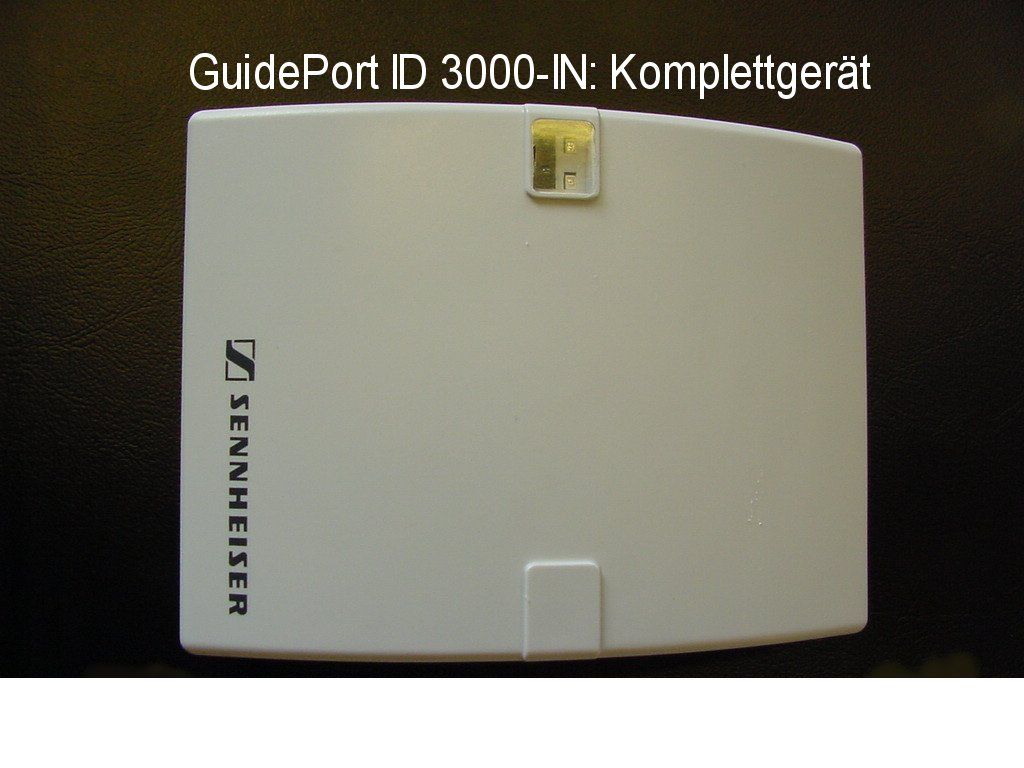
CETECOM ICT Services GmbH Test report no.: 2_2131-D/00Issue Date: 18.01.2001Page 14 (17) PHOTOGRAPHS OF THE EQUIPMENT ID 3000-IN Photograph no.: 1
ID Label/Location Info
This equipment will have the following FCC ID label located on the bottom of the unit. This device complies with Part 15 of the FCC Rules. Operation is subject to the following two conditions: (1) this device may not cause harmful interference, and (2) this device must accept any interference received, including interference that may cause undesired operation. FCC ID:DMOIDGPSF
ID Label/Location Info
This device complies with Part 15 of the FCC Rules. Operation is subject to the following two conditions: (1) this device may not cause harmful interference, and (2) this device must accept any interference received, including interference that may cause undesired operation . The equipment label will be located on the bottom of the unit as indicated above. Phillip Inglis TRP/Cetecom bvba FCC ID: DMOIDGPSF
Internal Photos
CETECOM ICT Services GmbH Test report no.: 2_2131-D/00Issue Date: 18.01.2001Page 15 (17) PHOTOGRAPHS OF THE EQUIPMENT ID 3000-IN Photograph no.: 2 CETECOM ICT Services GmbH Test report no.: 2_2131-D/00Issue Date: 18.01.2001Page 16 (17) PHOTOGRAPHS OF THE EQUIPMENT ID 3000-IN Photograph no.: 3 CETECOM ICT Services GmbH Test report no.: 2_2131-D/00Issue Date: 18.01.2001Page 17 (17) PHOTOGRAPHS OF THE EQUIPMENT ID 3000-IN Photograph no.: 4
Operational Description
GuidePort – EMP System Manual Version 1.0 of 27 July 2000 Sennheiser electronic GmbH & Co. KG Am Labor 1 30900 Wedemark Germany GuidePort: System Manual27. November 2000Seite 2 1 GuidePort Wireless Audio Transmission GuidePort is a local area broadcast system for use in museums, visitor centers and at exhibitions. GuidePort features a characteristic cell structure, the so-called cells being defined areas of information and entertainment. These areas are supplied byCell Transmitterswhich send digitally coded information via anActive Antenna Unitto portableReceivers. The transmitted data can be any audio information, for example comments or music. The audio signals are picked up by bodypack receivers which play the audio program directly via headphones. The various audio programs (events) can be triggered automatically bymagnetic field identifiers. The diagram on the next page shows GuidePort’s system hierarchy. At the top level are the GuidePort installations. Each installation carries a specific code transmitted via RF. Whenever a GuidePort receiver recognizes a new installation code, it will automatically collect the installation-specific control data. This data is mainly the so-called Event Assign Table which defines the receiver’s “reactions” to the 255 possible event numbers available in each installation, making the receiver compatible with other separate, independent GuidePort installations. An installation can be seen as a macro cell. Each installation can be organized in up to 255 cells and contains up to 255 real-time audio events. GuidePort: System Manual27. November 2000Seite 3 GuidePort Installation INST. No. 1 GuidePort Installation INST. No. 3 GuidePort Installation INST. No. 2 cell 1 cell 2 cell 3 cell 4 ... cell 255 cell 5 GuidePortCell with one or more Cell Transmitters Event 1Event 2 Event 3 Event 5 Event 4 Event 6 Event N Oneinstallation can handle up to 255 events which may be organized in up to 255 cells GuidePort System Hierarchy One celltransmitter can handle up to 4 mono audio channels and transmit them on one RF channel GuidePort: System Manual27. November 2000Seite 4 Cell Transmitter Central Unit PCwith •GP Central Unit Software •Sound card with a samplingrateof 32 kHz •G7++ converter and announcement software Base Station PC with Cell Transmitter Loader Software Base Station PC with Cell Transmitter Loader Software Audio Source 1 -4 PC Network Base Station PC with Cell Transmitter Loader Software USB Hub USB USB Hub Audio Source 1 -4 Active Antenna Unit RF CH 1 Cell Transmitter Active Antenna Unit RF CH 4 Cell Transmitter Event #3 Event #4 Event #5 Event #6 GP Receiver Ext. Antenna (opt.) Event #2 Event #1 Exhibition room 1 Exhibition room 2 Exhibition room 3 Exhibition room 7 Technical room 1 LVDS LVDS USB Exhibition room 5 Exhibition room 6 Exhibition room 4 Technical equipment required for an exhibition with GuidePort Supervisor GuidePort: System Manual27. November 2000Seite 5 2 Hardware Components of the System 2.1 Central Unit PC The Central Unit PC with its Central Unit Software is at the heart of the GuidePort system. It serves to configure the entire GuidePort installation with its cells, transmitters, events and identifiers. Via a network, the Central Unit PC is connected with all Base Station PCs of the GuidePort installation. 2.2 Base Station PC The Base Station PC with its Cell Transmitter Loader Software detects the IDs of all Cell Transmitters connected to it via a USB. The Base Station PC will transmit the configuration files created by the Central Unit Software to the Cell Transmitters. 2.3 Cell Transmitter 2.3.1 Description A Cell Transmitter is a digital unit which picks up prepared MTS data and combines them with installation-specific control tables and the real-time audio information from its four analog audio inputs. Via an LVDS interface, the entire data stream is sent to an Active Antenna Unit where FSK modulation and RF conversion take place. The transmission of the MTS data is done in a cyclic manner. The cable length between the Cell Transmitter and the Active Antenna Unit may amount to up to 150 m, which ensures a convenient installation of the local antennas. 1234 Analog RTA Inputs Cell Controller Unit USB Interface LVDS Interface Data Download To Active Antenna Unit Base Station GuidePort: System Manual27. November 2000Seite 6 2.3.2 Hardware Interfaces a)Front panel Headphone Outputs Allow you to monitor the audio signals transmitted to the receivers. b)Rear panel USB IN: Input socket for the USB cable from the Base Station PC. ANALOG IN SYM.: Inputs for connecting your audio sources to the transmitter. There are four balanced inputs, you can either connect 4 mono sources, 2 mono sources and 1 stereo source or 2 stereo sources. For a stereo audio source, you will need two sockets (left and right channel), please use inputs 1 & 2 and/or 3 & 4. Connect the left audio channel to socket No. 1 or 3, the right audio channel to No. 2 or 4, respectively. The following table shows how to connect your audio sources to the GuidePort Cell Transmitter: Number and kind of audio sources Input No. 1Input No. 2Input No. 3Input No. 4 4 mono (m)mmmm 2mono(m),1stereo(s)mms,lefts,right 2 stereo (s)s, lefts, rights, lefts, right AAU OUT Output for connection of an Active Antenna Unit. Use a shielded, 8-wire twisted pair cable (4 individually twisted pairs) for connection. This cable supplies the Active Antenna Unit with DC and the digital data stream to be transmitted. SETSET GuidePortSR3000-2 TX ITX II TX II AAU OUT 0 I USB IN ANALOG IN SYM. TIP: + RING:- 1 234 TX I AAU OUT USB IN ANALOG IN SYM. TIP: + RING:- 1 234 GuidePort: System Manual27. November 2000Seite 7 2.3.3 User Interface (Display and Controls) Menu layout of the GuidePort Cell Transmitter: AAU SETTINGS SETSET AAU 01 AAU 02 AAU 08 RF CHxx EXT ANT xx MTS xx RF ATTEN xx SET SET SET 1...95 NC ON OFF NC 01 02 OFF 00...06 TX OK CCU ID xxx SET SET RTA VOLVOL xx SET Max. 32 Default 16 Min.1 SET RTA…
Text truncated - open the document above for the full version.
Test Report
CETECOM ICT Services GmbH Radio Satellite Communication Untertürkheimer Straße 6-10 . D-66117 SaarbrückenTelefon: +49 (0)681 598-9100Telefax: -9075 RSC11issue test report consist of17 PagesPage 1 (17) Test report no.: 2_2131-D/00 FCC Rule 15.209 / USA ID 3000-IN Akkreditiertes Prüflaboratorium DAR-Registriernummer: TTI-P-G 166/98 CETECOM ICT Services GmbH Test report no.: 2_2131-D/00Issue Date: 18.01.2001Page 2 (17) Table of Contents 1 General information 1.1 Notes 1.2 Testing laboratory 1.3 Details of applicant 1.4 Application details 1.5 Test item 1.6 Test standards 2 Technical test 2.1 Summary of test results 2.2 Test report 1 General information 1.1 Notes The test results of this test report relate exclusively to the test item specified in 1.5. The CETECOM ICT Services GmbH does not assume responsibility for any conclusions and generalisations drawn from the test results with regard to other specimens or samples of the type of the equipment represented by the test item. The test report may only be reproduced or published in full. Reproduction or publication of extracts from the report requires the prior written approval of the CETECOM ICT Services GmbH. CETECOM ICT Services GmbH Test report no.: 2_2131-D/00Issue Date: 18.01.2001Page 3 (17) 1.2Testing laboratory CETECOM ICT Services GmbH Untertürkheimer Straße 6 – 10 66117 Saarbrücken Deutschland Telefone: + 49 681 598 - 9000 Telefax : + 49 681 598 - 9075 E-mail: [email protected] Internet: www.cetecom.de Accredited testing laboratory DAR-registration number : TTI-P-G-166/98 1.3Details of applicant Name :Sennheiser electronic GmbH & Co. KG Street :Am Labor 1 City :D-30900 Wedemark Country :Germany Telephone:+49 (51 30) 600-0 Telefax :+49 (51 30) 600-300 Contact :Mr. Klaus Willemsen Telephone:+49 (51 30) 600-542 1.4Application details Date of receipt of application : 07.12.2000 Date of receipt of test item : 07.12.2000 Date of test : 19./20.12.2000 1.5Test item Type of equipment :location transmitter Type designation: ID 3000-IN Manufacturer:applicant Street: City: Country: Serial number: see photos Additional informations:: Frequency: 127 kHz / 24K0F1D Number of channels : 1 Antenna: indoor loop antenna/ coil antenna Power supply:6V DC (4* 1,5 V Battery) or external 6-12V DC Type of equipment : - Carrier power: 1.6Test standards: FCC Rule Part 15.209 CETECOM ICT Services GmbH Test report no.: 2_2131-D/00Issue Date: 18.01.2001Page 4 (17) 2 Technical test 2.1Summary of test results No deviations from the technical specification(s) were ascertained in the course of the tests performed. Technical responsibility for area of testing : 2001-01-18RSC8412Hausknecht M DateSectionNameSignature 2001-01-18RSC8414Ames H. DateSectionNameSignature CETECOM ICT Services GmbH Test report no.: 2_2131-D/00Issue Date: 18.01.2001Page 5 (17) 2.2Test report TEST REPORT FCC Rule Part 15.209 Test report no. : 2_2131-D/00 CETECOM ICT Services GmbH Test report no.: 2_2131-D/00Issue Date: 18.01.2001Page 6 (17) TEST REPORT REFERENCE LIST OF MEASUREMENTS SUBCLAUSEPARAMETER TO BE MEASUREDPAGE Transmitter parameters § 15.209Field strength of fundamental7 § 15.209Emissions radiated outside of the specified frequency band8 § 15.207Conducted limits11 Test equipment listing12 Photographs of the equipment14 CETECOM ICT Services GmbH Test report no.: 2_2131-D/00Issue Date: 18.01.2001Page 7 (17) Equipment under test : ID 3000-IN Ambient temperature: 23°C Relative humidity : 30% REFERENCE NUMBER(S) OF TEST EQUIPMENT USED (for reference numbers see test equipment listing) 17 - 24 FIELD STRENGTH OF FUNDAMENTAL SUBCLAUSE § 15.209 Polarisation of the measurements for the larger power level .: vertical Measurement distance 300 m TEST CONDITIONSFIELD STRENGTH (μV/m ) Frequency (MHz)0.127 T nom ( 23 )°C V nom ( 6 / 12 )V18.5 Maximum deviation from output power under extreme test conditions (dBc) -0,8 Measurement uncertainty±3dB Limit : 18,9μV/m Limits SUBCLAUSE § 15.209 Frequency (MHz)Field strength (μV/m)Measurement distance (m) 0.009 - 0.4902400/F(kHz)300 0.490 - 1.70524000/F(kHz)30 1.705 - 30.03030 30 - 881003 88 - 2161503 216 - 9602003 above 9605003 CETECOM ICT Services GmbH Test report no.: 2_2131-D/00Issue Date: 18.01.2001Page 8 (17) Equipment under test : ID 3000-IN Ambient temperature: 23°C Relative humidity : 30% REFERENCE NUMBER(S) OF TEST EQUIPMENT USED (for reference numbers see test equipment listing) 17 - 24 EMISSIONS RADIATEDSUBCLAUSE §15.209 Transmitter operatingModulated/Unmodulated* *(Delete whichever is inappropriate) Measurement distance see table SPURIOUS EMISSIONS LEVEL (μV/m) 0.127 MHz f (MHz) DetectorLevel (μV/m) f (MHz) DetectorLevel (μV/m) f (MHz) DetectorLevel (μV/m) 0.38QP0,6 Measurement uncertainty± 3dB Measurement was made with a CISPR QP-adapter and 10 kHz BW. Limits SUBCLAUSE § 15.209 Frequency (MHz)Field strength (μV/m)Measurement distance (m) 0.009 - 0.4902400/F(kHz)300 0.490 - 1.70524000/F(kHz)30 1.705 - 30.03030 30 - 881003 88 - 2161503 216 - 9602003 above 9605003 CETECOM ICT Services GmbH Test report no.: 2_2131-D/00Issue Date: 18.01.2001Page 9 (17) Equipment under test : ID 3000-IN Ambient temperature: 23°C Relative humidity : 30% REFERENCE NUMBER(S) OF TEST EQUIPMENT USED (for reference numbers see test equipment listing) 17 - 24 EMISSIONS RADIATEDSUBCLAUSE §15.209 This scan was made with an automatic test system from R&S and the software ESK1. It shows the behavior of the 127 kHz TX radiated up to 30 MHz. The limit line in the plot is calculated for 300 m, but the test was performed at 30m. So we have a readout, that is 20 dB to high (real 18.5 μV/m) and the peak at 380 kHz is 30 dB below carrier at 127 kHz (real 0.6 μV/m). CETECOM ICT Services GmbH Test report no.: 2_2131-D/00Issue Date: 18.01.2001Page 10 (17) Equipment under test : ID 3000-IN Ambient temperature: 23°C Relative humidity : 30% REFERENCE NUMBER(S) OF TEST EQUIPMENT USED (for reference numbers see test equipment listing) 17 - 24 EMISSIONS RADIATEDSUBCLAUSE §15.209 no p…
Text truncated - open the document above for the full version.
Test Report
Field Strength level in uV/m Freque ncy 30 meter distance300 meter distance 127 kHz18518.5 380 kHz 5.85 ≅ 6≅ 0.6 This table was generated to respond to the questions raised by the FCC regarding table 9 of the test report. The levels of signals as represented on the graph were made at a distance of 30 meters by the Rhode and Swartz measurement system and graphed by computer. The FCC limit line calculated by the Part 15 formula for a distance of 300 meters was added to the computer program and then graphed on the same curve. This produced the confusion over the representations shown on the graph. The curve of measured levels is for levels measured at 30 meters while the FCC limit line if for levels measured at 300 meters. The paragraph under the graph on Page 9 explains the above. Cetecom then used an inverse linear extrapolation rate to show the measured 127 kHz level of 185 uV/m as measured at 30 meters would extrapolate to a value of 18.5 uV/m if measured at 300 meters. The FCC rules actually permit an extrapolation rate of inverse square in this frequency range. Using the permitted inverse square extrapolation rate, the reported levels for 300 meters would be 20 dB below the levels in the above table or 1.85 uV/m at 300 meters for the fundamental and 0.06 uV/m for the spurious emission at 380 kHz. One other point I would like to clarify is that Cetecom referenced a frequency of 380 kHz from the graph. A closer examination of the frequency shows it is much closer to 350 kHz that would coincide with the 354 kH z seco nd har mo nic of the funda me ntal. Phillip Inglis TRP/Cetecom bvba
Contact Information
Applicant
Michael Lieske
Technical Contact
TRP/Cetecom bvbaPhillip Inglis
[email protected]410-531-3439
14085 Howard Rd · Dayton, Maryland · United States
Non-Technical Contact
TRP/Cetecom bvbaPhillip Inglis
[email protected]410-531-3439
Test Firm
Cetecom ICT Services GmbHRalf Hoehn
Technical Specifications
| # | Rule Parts | Frequency Range | Power Output |
|---|---|---|---|
| 1 | 15C | 0.127 MHz - 0.127 MHz | - |
Other Applications from Sennheiser Electronic Corp
DMOSKM1G4
Aug 19, 2026Handheld Transmitter
Equipment Class
TLD - Licensed LPAS DeviceDMOSKMUHF
May 20, 2026Antenna Transceiver
Equipment Class
DWM - Part 15 Wireless Microphone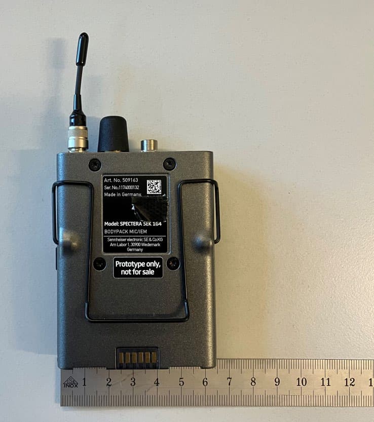
DMOSEK1G4
Mar 11, 2026Bodypack Mic/IEM
Equipment Class
TLD - Licensed LPAS Device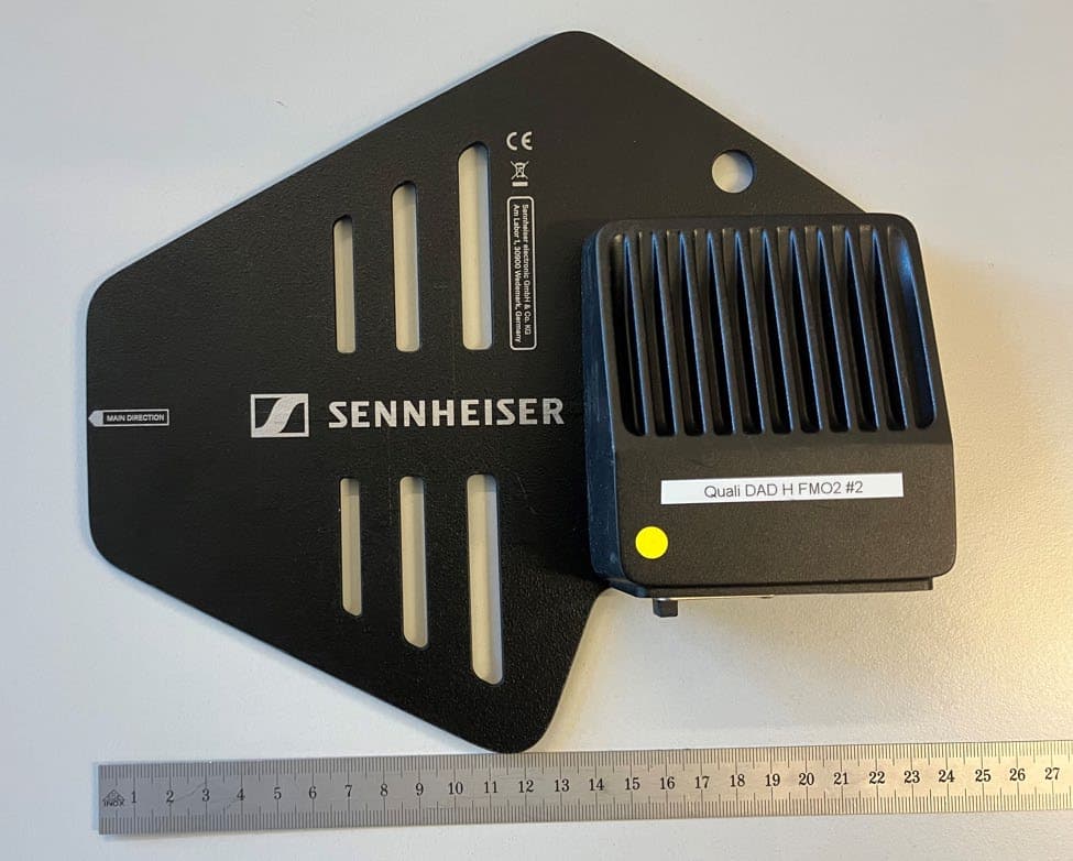
DMODAD1G4
Mar 11, 2026Antenna Transceiver
Equipment Class
TLD - Licensed LPAS DeviceDMOTSEWDX
Jan 30, 2024Wireless Table Stand
Equipment Class
TLD - Licensed LPAS Device