DMOLSP500Wireless Integrated PA System
Sennheiser Electronic Corp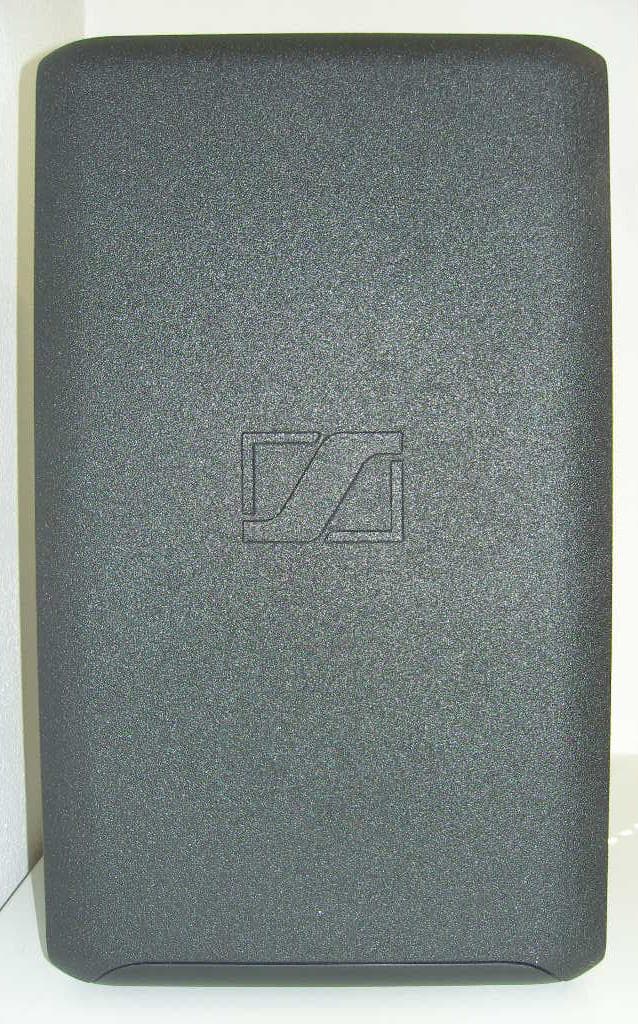
Click to zoom
Application Details
- Equipment Class
- DTS - Digital Transmission System
- Date of Grant
- Jul 16, 2013
- Application Purpose
- Original Equipment
- Date of Application
- Jul 16, 2013
- Equipment Note
- Wireless Integrated PA System
- Frequency Range
- 2412.00000000 - 2462.00000000
- Company
- Sennheiser Electronic Corp
- Country
- United States
Documents & Files
Document Text
Text extracted from the exhibit documents filed with the FCC. Open a document above to read the original.
Users Manual
LSP 500 PRO Wireless Integrated PA System Bedienungsanleitung Instruction manual 2 | LSP 500 PRO Content Content Important safety instructions ...................................................................................3 LSP 500 PRO .................................................................................................................6 Package contents .........................................................................................................7 Product overview .........................................................................................................8 Operating elements .....................................................................................................9 Using the LSP 500 PRO.............................................................................................10 Installing the LSP 500 PRO ......................................................................................10 Mains and battery operation ..................................................................................11 Important information on battery operation ......................................................13 Switching the LSP 500 PRO on ................................................................................14 Basic operating functions ........................................................................................15 Basic indications and functions shown on the display panel ...........................16 Lock mode ...................................................................................................................18 Activating ground lift ...............................................................................................18 Connection possibilities ............................................................................................19 Installing devices in the expansion slots ..............................................................20 Operating the LSP 500 PRO via a tablet ................................................................23 The operating menu .................................................................................................28 Menu structure...........................................................................................................28 Equalizer ......................................................................................................................29 Master EQ ................................................................................................................30 EQ presets for the inputs ......................................................................................31 Virtual Bass .................................................................................................................32 Compressor .................................................................................................................32 Delay ............................................................................................................................34 USB player ...................................................................................................................35 Bluetooth ....................................................................................................................38 Settings .......................................................................................................................40 Test sound ...............................................................................................................40 Configuring the signal output to additional devices ......................................41 Display brightness .................................................................................................42 WLAN .......................................................................................................................42 Configuring the MIC input ....................................................................................50 Detecting devices in the expansion slots ..........................................................51 Resetting the settings ..........................................................................................52 Service .........................................................................................................................53 System information ..............................................................................................53 Updating the firmware .........................................................................................54 Cleaning and maintaining the LSP 500 PRO .........................................................55 Cleaning .......................................................................................................................55 Storage ........................................................................................................................55 If a problem occurs ... ...............................................................................................56 Specifications ............................................................................................................59 Accessories ................................................................................................................61 Manufacturer Declarations .....................................................................................62 LSP 500 PRO | 3 Important safety instructions Important safety instructions 1. Read this instruction manual. 2. Keep this instruction manual. Always include this instruction manual when passing the apparatus on to third parties. 3. Heed all warnings. 4. Follow all instructions. 5. Do not use this apparatus near water. 6. Only clean the apparatus when it is not connected to the mains power supply. Clean only with a dry cloth. 7. Always ensure a free air flow around the cooling fins on the rear of the product. Do not block a…
Text truncated - open the document above for the full version.
Users Manual
36 | LSP 500 PRO The operating menu Playback mode Jog dialActionIconFunction MENU Returns to the home screen SLOT 1 Selects a playback option: Random Sequence Single track SLOT 2 Repeat function activated Repeat function deactivated SLOT 3 Changes to recording mode MIC Short press: jumps to the previous track Long press: rewinds the track AUX IN Browses through the playlist without stopping the current track AUX IN Play Pause USB Short press: jumps to the next track Long press: fast-forwards the track Display example when USB player is in playback mode Display example when USB player is in playback mode and during playback Using the USB player in playback mode LSP 500 PRO | 37 The operating menu Recording mode The time display on the display panel indicates the remaining recording time left on the storage device. Jog dialActionIconFunction MENU Returns to the home screen SLOT 3 Stops the recording and changes to play- back mode AUX IN Record Pause Notes on handling recording files You can either create a new file for each recording or you can append additional recordings to the same file. Recordings are saved as WAV files (stereo / 16 bit / 44.1 kHz). To create a new recording file for each recording: XChange from playback mode to recording mode. XPress the AUX IN jog dial to start the recording. XPress the SLOT 3 jog dial to end the recording and to change to playback mode. XChange from playback mode to recording mode. XPress the AUX IN jog dial to start the recording. A new recording file is created. The number at the end of the file name is incre- mented by one for each new recording file. To make multiple recordings in the same file: XChange from playback mode to recording mode. XPress the AUX IN jog dial to start the recording. XPress the AUX IN jog dial to stop the recording. XPress the AUX IN jog dial to resume recording to the same file. As long as you do not stop recording mode by pressing the SLOT 3 jog dial, you continue recording to the same file after recording has been stopped. Display example when USB player is in recording mode Display example when USB player is in recording mode and during recording Using the USB player in recording mode 38 | LSP 500 PRO The operating menu Bluetooth Via the Bluetooth menu, you can pair a mobile device (e.g. smartphone, tablet) with the LSP 500 PRO in order to be able to play audio files. The LSP 500 PRO supports the A2DP protocol (SBC and aptX®). To open the Bluetooth menu: XAt the first menu level, turn the MENU jog dial until the BLUETOOTH menu item is displayed. XPress the MENU jog dial to open the BLUETOOTH menu item. XTurn the MENU jog dial to choose between PAIRING and VOLUME. XPress the MENU jog dial to open the selected menu item. Adjusting the volume for the Bluetooth interface To adjust the input volume for the Bluetooth interface: XOpen the VOLUME menu item. XTurn the MENU jog dial to adjust the desired input volume for the Bluetooth interface. XPress the MENU jog dial to store the adjusted volume. It is recommended to adjust the volume for the Bluetooth interface as high as possible in order to minimize possible noise (hissing or similar). During operation, adjust the volume on the Bluetooth device itself. Menu Bluetooth Volume LSP 500 PRO | 39 The operating menu Pairing Bluetooth devices To pair a Bluetooth device with the LSP 500 PRO: XOpen the PAIRING menu item. XTurn the MENU jog dial to choose between OFF and PAIR. XPress the MENU jog dial to activate your selection. XSelect OFF to cancel pairing or to end an existing Bluetooth connection. XSelect PAIR to pair a Bluetooth device with the LSP 500 PRO: Pairing mode is activated. PAIRING NOW appears on the display panel and the Bluetooth icon flashes in the status area. XPair your Bluetooth device with the LSP 500 PRO while pairing mode is active. When the Bluetooth connection is successfully established, PAIRING SUCCESSFUL appears on the display panel and the Bluetooth icon is displayed steadily in the status area. When the Bluetooth connection is not made or after an automatic time-out of 30 seconds, PAIRING FAILED appears on the display panel. XPress the SLOT 3 jog dial to retry pairing. Your Bluetooth device displays the LSP 500 PRO as follows: LSP500-XXXXX. XXXXX stands for the last 5 digits of the LSP 500 PRO‘s serial number. The LSP 500 PRO supports automatic reconnection to the last connected device. For information on whether your device supports this function, refer to the instruction manual of your Bluetooth device. Pairing 40 | LSP 500 PRO The operating menu Settings The SETTINGS menu allows you to adjust the LSP 500 PRO settings. To open the settings menu: XAt the first menu level, turn the MENU jog dial until the SETTINGS menu item is displayed. XPress the MENU jog dial to open the SETTINGS menu item. The SETTINGS menu contains all the options and functions necessary for con- figuring the LSP 500 PRO. Test sound You can play a test sound to check the acoustic function of the LSP 500 PRO. To play the test sound: XIn the SETTINGS menu, turn the MENU jog dial until the TEST SOUND menu item is displayed. XPress the MENU jog dial to open the TEST SOUND menu item. XTurn the MENU jog dial to adjust the volume of the test sound. XPress the MENU jog dial (or the SLOT 1 jog dial) to adjust the volume of the test sound to 0 and to return to the previous menu level. The overall volume of the LSP 500 PRO and the volume of the test sound have no effect on one another. When the test sound is activated, the other signals of the LSP 500 PRO are muted. After existing the TEST SOUND menu item, the previous volume settings are activated again. Menu Settings Settings Menu Test Sound LSP 500 PRO | 41 The operating menu Configuring the signal output to additional devices You can send the signal of the LSP 500 PRO to one or several LSP 500 PRO – either wired via the LINK OUT XLR output or wirelessly via a transmitter installed in the SLOT 1 expansion slot. Via the LINK OUT output, yo…
Text truncated - open the document above for the full version.
Cover Letter(s)
Request for Confidentiality Date: 17.07.2013 Subject: Confidentiality Request for: FCC ID: DMOLSP500 IC: 2099A-LSP500 Pursuant to FCC 47 CRF 0.457(d) and 0.459 and IC RSP-100, Section 10, the applicant requests that a part of the subject FCC application be held confidential. Type of Confidentiality Requested Exhibit Short Term Permanent Block Diagrams Short Term External Photos Short Term Permanent* 1 Internal Photos Short Term Permanent Operation Description/Theory of Operation Short Term Permanent Parts List & Placement/BOM Short Term Permanent Tune-Up Procedure Short Term Permanent Schematics Short Term Test Setup Photos Short Term Permanent* User’s Manual *Note: Internal Photos shall be hold confidential as the device is not accessible to the general public, it is only serviceable by the licensee or designated technicians. Sennheiser Electronic Corp. has spent substantial effort in developing this product and it is one of the first of its kind in industry. Having the subject information easily available to "competition" would negate the advantage they have achieved by developing this product. Not protecting the details of the design will result in financial hardship. Permanent Confidentiality: The applicant requests the exhibits listed above as permanently confidential be permanently withheld from public review due to materials that contain trade secrets and proprietary information not customarily released to the public. Short-Term Confidentiality: The applicant requests the exhibits selected above as short term confidential be withheld from public view for a period of (0) days from the date of the Grant of Equipment Authorization and prior to marketing. This is to avoid premature release of sensitive information prior to marketing or release of the product to the public. Applicant is also aware that they are responsible to notify ACB in the event information regarding the product or the product is made available to the public. ACB will then release the documents listed above for public disclosure pursuant to FCC Public Notice DA 04-1705. NOTE for Industry Canada Applications: The applicant understands that until such time that IC distinguishes between Short Term and Permanent Confidentiality, either type of marked exhibit above will simply be marked Confidential when submitted to IC. Sincerely, By: Manager Certification Thomas Ring Title Name 1 - The asterisked items (*) require further justification before permanent confidentiality will be allowed. These also currently require review by the FCC under their Permit-But-Ask policy before the grant is issued and can delay completion of an application. Further justification should be added to the note above. One such example for a potted device would be: “The EUT is FULLY potted using a non-removable epoxy based material. Removal of potting material causes irreparable damage to internal circuitry. See photographs exhibits that outline the device before and after potting.”
External Photos
mikes-testingpartners gmbh File No. T36407-00, page 1 of 19 Ohmstrasse 2-4 94342 STRASSKIRCHEN GERMANY Tel.: +49(0)9424-94810 Fax: +49(0)9424-9481240 Rev. No. 1.2, 2013-04-04 EMI − T E S T R E P O R T Attachment A to Test Report No. : T36407-00 09. July 2013 ______________________________________________________________________________________________ Date of issue Type / Model Name : LSP 500 PRO Product Description : Wireless Integrated PA System Applicant : Sennheiser electronic GmbH & Co. KG Address : Am Labor 1 30900 WEDEMARK, GERMANY Manufacturer : Sennheiser electronic GmbH & Co. KG Address : Am Labor 1 30900 WEDEMARK, GERMANY Licence holder : Sennheiser electronic GmbH & Co. KG Address : Am Labor 1 30900 WEDEMARK, GERMANY The test report merely corresponds to the test sample. It is not permitted to copy extracts of these test results without the written permission of the test laboratory. mikes-testingpartners gmbh File No. T36407-00, page 2 of 19 Ohmstrasse 2-4 94342 STRASSKIRCHEN GERMANY Tel.: +49(0)9424-94810 Fax: +49(0)9424-9481240 Rev. No. 1.2, 2013-04-04 Contents 1 P h o t o d o c u m e n t a t i o n o f t h e E U T 3 1.1 The EUT is applied in the following hand remote control variants:Fehler! Textmarke nicht definiert. 1.2 External views: Fehler! Textmarke nicht definiert. 1.3 Internal views Fehler! Textmarke nicht definiert. 1.4 Antenna structure: Fehler! Textmarke nicht definiert. mikes-testingpartners gmbh File No. T36407-00, page 3 of 19 Ohmstrasse 2-4 94342 STRASSKIRCHEN GERMANY Tel.: +49(0)9424-94810 Fax: +49(0)9424-9481240 Rev. No. 1.2, 2013-04-04 1 P h o t o d o c u m e n t a t i o n o f t h e E U T 1.1 Radiated sample 1.1.1 External view: Front mikes-testingpartners gmbh File No. T36407-00, page 4 of 19 Ohmstrasse 2-4 94342 STRASSKIRCHEN GERMANY Tel.: +49(0)9424-94810 Fax: +49(0)9424-9481240 Rev. No. 1.2, 2013-04-04 Rear mikes-testingpartners gmbh File No. T36407-00, page 5 of 19 Ohmstrasse 2-4 94342 STRASSKIRCHEN GERMANY Tel.: +49(0)9424-94810 Fax: +49(0)9424-9481240 Rev. No. 1.2, 2013-04-04 mikes-testingpartners gmbh File No. T36407-00, page 6 of 19 Ohmstrasse 2-4 94342 STRASSKIRCHEN GERMANY Tel.: +49(0)9424-94810 Fax: +49(0)9424-9481240 Rev. No. 1.2, 2013-04-04 mikes-testingpartners gmbh File No. T36407-00, page 18 of 19 Ohmstrasse 2-4 94342 STRASSKIRCHEN GERMANY Tel.: +49(0)9424-94810 Fax: +49(0)9424-9481240 Rev. No. 1.2, 2013-04-04 1.2 Conducted sample: 1.2.1 External view: New design of the rear plate. mikes-testingpartners gmbh File No. T36407-00, page 19 of 19 Ohmstrasse 2-4 94342 STRASSKIRCHEN GERMANY Tel.: +49(0)9424-94810 Fax: +49(0)9424-9481240 Rev. No. 1.2, 2013-04-04 1.2.1 Internal view:
ID Label/Location Info
204-360003 6.3 mm LSP 500 PRO ARTWORK PART 2 (2013 04 29) BACKPLATE SCALE 1:1 ARTWORK SCALE 1:1 / ORIGINAL COLOUR (PANTONE 428C) / NAME PLATE: PANTONE COOL GRAY 4C
Internal Photos
mikes-testingpartners gmbh File No. T36407-00, page 1 of 19 Ohmstrasse 2-4 94342 STRASSKIRCHEN GERMANY Tel.: +49(0)9424-94810 Fax: +49(0)9424-9481240 Rev. No. 1.2, 2013-04-04 EMI − T E S T R E P O R T Attachment A to Test Report No. : T36407-00 09. July 2013 ______________________________________________________________________________________________ Date of issue Type / Model Name : LSP 500 PRO Product Description : Wireless Integrated PA System Applicant : Sennheiser electronic GmbH & Co. KG Address : Am Labor 1 30900 WEDEMARK, GERMANY Manufacturer : Sennheiser electronic GmbH & Co. KG Address : Am Labor 1 30900 WEDEMARK, GERMANY Licence holder : Sennheiser electronic GmbH & Co. KG Address : Am Labor 1 30900 WEDEMARK, GERMANY The test report merely corresponds to the test sample. It is not permitted to copy extracts of these test results without the written permission of the test laboratory. mikes-testingpartners gmbh File No. T36407-00, page 2 of 19 Ohmstrasse 2-4 94342 STRASSKIRCHEN GERMANY Tel.: +49(0)9424-94810 Fax: +49(0)9424-9481240 Rev. No. 1.2, 2013-04-04 Contents 1 P h o t o d o c u m e n t a t i o n o f t h e E U T 3 1.1 The EUT is applied in the following hand remote control variants:Fehler! Textmarke nicht definiert. 1.2 External views: Fehler! Textmarke nicht definiert. 1.3 Internal views Fehler! Textmarke nicht definiert. 1.4 Antenna structure: Fehler! Textmarke nicht definiert. mikes-testingpartners gmbh File No. T36407-00, page 7 of 19 Ohmstrasse 2-4 94342 STRASSKIRCHEN GERMANY Tel.: +49(0)9424-94810 Fax: +49(0)9424-9481240 Rev. No. 1.2, 2013-04-04 1.1.2 Internal view: mikes-testingpartners gmbh File No. T36407-00, page 8 of 19 Ohmstrasse 2-4 94342 STRASSKIRCHEN GERMANY Tel.: +49(0)9424-94810 Fax: +49(0)9424-9481240 Rev. No. 1.2, 2013-04-04 mikes-testingpartners gmbh File No. T36407-00, page 9 of 19 Ohmstrasse 2-4 94342 STRASSKIRCHEN GERMANY Tel.: +49(0)9424-94810 Fax: +49(0)9424-9481240 Rev. No. 1.2, 2013-04-04 mikes-testingpartners gmbh File No. T36407-00, page 10 of 19 Ohmstrasse 2-4 94342 STRASSKIRCHEN GERMANY Tel.: +49(0)9424-94810 Fax: +49(0)9424-9481240 Rev. No. 1.2, 2013-04-04 mikes-testingpartners gmbh File No. T36407-00, page 11 of 19 Ohmstrasse 2-4 94342 STRASSKIRCHEN GERMANY Tel.: +49(0)9424-94810 Fax: +49(0)9424-9481240 Rev. No. 1.2, 2013-04-04 mikes-testingpartners gmbh File No. T36407-00, page 12 of 19 Ohmstrasse 2-4 94342 STRASSKIRCHEN GERMANY Tel.: +49(0)9424-94810 Fax: +49(0)9424-9481240 Rev. No. 1.2, 2013-04-04 mikes-testingpartners gmbh File No. T36407-00, page 13 of 19 Ohmstrasse 2-4 94342 STRASSKIRCHEN GERMANY Tel.: +49(0)9424-94810 Fax: +49(0)9424-9481240 Rev. No. 1.2, 2013-04-04 mikes-testingpartners gmbh File No. T36407-00, page 14 of 19 Ohmstrasse 2-4 94342 STRASSKIRCHEN GERMANY Tel.: +49(0)9424-94810 Fax: +49(0)9424-9481240 Rev. No. 1.2, 2013-04-04 mikes-testingpartners gmbh File No. T36407-00, page 15 of 19 Ohmstrasse 2-4 94342 STRASSKIRCHEN GERMANY Tel.: +49(0)9424-94810 Fax: +49(0)9424-9481240 Rev. No. 1.2, 2013-04-04 mikes-testingpartners gmbh File No. T36407-00, page 16 of 19 Ohmstrasse 2-4 94342 STRASSKIRCHEN GERMANY Tel.: +49(0)9424-94810 Fax: +49(0)9424-9481240 Rev. No. 1.2, 2013-04-04 1.1.3 Battery pack: mikes-testingpartners gmbh File No. T36407-00, page 17 of 19 Ohmstrasse 2-4 94342 STRASSKIRCHEN GERMANY Tel.: +49(0)9424-94810 Fax: +49(0)9424-9481240 Rev. No. 1.2, 2013-04-04 mikes-testingpartners gmbh File No. T36407-00, page 19 of 19 Ohmstrasse 2-4 94342 STRASSKIRCHEN GERMANY Tel.: +49(0)9424-94810 Fax: +49(0)9424-9481240 Rev. No. 1.2, 2013-04-04 1.2.1 Internal view:
Test Report
FCC ID: DMOLSP500 IC ID: 2099A-LSP500 mikes-testingpartners gmbh File No. T36407-00-03HS, page 1 of 60 Ohmstrasse 2-4 94342 STRASSKIRCHEN GERMANY Tel.:+49(0)9424-94810 Fax: ++49(0)9424-9481240 Rev. No. 1.3, 2013-04-04 EMI − T E S T R E P O R T - FCC Part 15.247, RSS210 - Test Report No. : T36407-00-03HS 09. July 2013 ______________________________________________________________________________________________ Date of issue Type / Model Name : LSP 500 PRO Product Description : Wireless Integrated PA System Applicant : Sennheiser electronic GmbH & Co. KG Address : Am Labor 1 30900 WEDEMARK, GERMANY Manufacturer : Sennheiser electronic GmbH & Co. KG Address : Am Labor 1 30900 WEDEMARK, GERMANY Licence holder : Sennheiser electronic GmbH & Co. KG Address : Am Labor 1 30900 WEDEMARK, GERMANY Test Result according to the standards listed in clause 1 test standards: POSITIVE The test report merely corresponds to the test sample. It is not permitted to copy extracts of these test results without the written permission of the test laboratory. FCC ID: DMOLSP500 IC ID: 2099A-LSP500 mikes-testingpartners gmbh File No. T36407-00-03HS, page 2 of 60 Ohmstrasse 2-4 94342 STRASSKIRCHEN GERMANY Tel.:+49(0)9424-94810 Fax: ++49(0)9424-9481240 Rev. No. 1.3, 2013-04-04 Contents 1 T E S T S T A N D A R D S 3 2 S U M M A R Y 4 2.1 Test result summery 4 2.2 General remarks 5 2.3 Final assessment 6 3 E Q U I P M E N T U N D E R T E S T 7 3.1 Photo documentation of the EUT – Detailed photos see attachment A 7 3.2 Power supply system utilised 7 3.3 Short description of the equipment under test (EUT) 7 4 T E S T E N V I R O N M E N T 8 4.1 Address of the test laboratory 8 4.2 Environmental conditions 8 4.3 Statement of the measurement uncertainty 8 4.4 Measurement protocol for FCC and IC 9 4.5 Determination of worst case measurement conditions 10 5 T E S T C O N D I T I O N S A N D R E S U L T S 11 5.1 Conducted emissions 11 5.2 Emission bandwidth and occupied bandwith 15 5.3 Maximum peak conducted output power 23 5.4 Out-of-band emission, conducted 25 5.5 Out-of-band emission, radiated (cabinet radiation) 35 5.6 Out-of-band emission in restricted bands, conducted 39 5.7 Out-of-band emission in restricted bands, radiated 43 5.8 Power spectral density 51 5.9 Maximum permissible exposure (MPE) 56 5.10 Co-location and Co-transmission 58 5.11 Antenna application 59 6 U S E D T E S T E Q U I P M E N T A N D A C C E S S O R I E S 60 Attachment A see separate supplement FCC ID: DMOLSP500 IC ID: 2099A-LSP500 mikes-testingpartners gmbh File No. T36407-00-03HS, page 3 of 60 Ohmstrasse 2-4 94342 STRASSKIRCHEN GERMANY Tel.:+49(0)9424-94810 Fax: ++49(0)9424-9481240 Rev. No. 1.3, 2013-04-04 1 T E S T S T A N D A R D S The tests were performed according to following standards: FCC Rules and Regulations Part 15, Subpart A - General (September, 2012) Part 15, Subpart A, Section 15.31 Measurement standards Part 15, Subpart A, Section 15.33 Frequency range of radiated measurements Part 15, Subpart A, Section 15.35 Measurement detector functions and bandwidths FCC Rules and Regulations Part 15, Subpart C - Intentional Radiators (September, 2012) Part 15, Subpart C, Section 15.203 Antenna requirement Part 15, Subpart C, Section 15.204 External radio frequency power amplifiers and antenna modifications Part 15, Subpart C, Section 15.205 Restricted bands of operation Part 15, Subpart C, Section 15.207 Conducted limits Part 15, Subpart C, Section 15.209 Radiated emission limits, general requirements Part 15, Subpart C, Section 15.247 Operation within the bands 902 - 928 MHz, 2400 - 2483.5 MHz and 5725 - 5850 MHz FCC Rules and Regulations Part 1, Subpart I - Procedures Implementing the National Environmental Policy Act of 1969 Part 1, Subpart I, Section 1.1310 Radiofrequency radiation exposure limits Part 1, Subpart 2, Section 2.1093 Radiofrequency radiation exposure evaluation: portable device OET Bulletin 65, 65A, 65B, 65C Edition 97-01, August 1997 – Evaluating Compliance with FCC Guidelines for Human Exposure to Radio Frequency Electromagnetic Fields. ANSI C63.4: 2003 Methods of Measurement of Radio-Noise Emissions from Low- Voltage Electrical and Electronic Equipment in the Range of 9 kHz to 40 GHz. ANSI C95.1: 2005 IEEE Standard for Safety Levels with respect to Human Exposure to Radio Frequency Electromagnetic Fields, 3 kHz to 300 GHz CISPR 16-4-2: 2003 Uncertainty in EMC measurement CISPR 22: 2005 Information technology equipment EN 55022: 2006 KDB 558074 D01 v03 Guidance for performing compliance measurements on DTS operating under Section 15.247, April 9, 2013. FCC ID: DMOLSP500 IC ID: 2099A-LSP500 mikes-testingpartners gmbh File No. T36407-00-03HS, page 4 of 60 Ohmstrasse 2-4 94342 STRASSKIRCHEN GERMANY Tel.:+49(0)9424-94810 Fax: ++49(0)9424-9481240 Rev. No. 1.3, 2013-04-04 2 S U M M A R Y 2.1 Test result summery WLAN device using digital modulation and operates in the 2400 MHz – 2483.5 MHz band: FCC Rule Part RSS Rule Part Description Result 15.207(a) RSS Gen, 7.2.4. AC power line conducted emissions passed 15.247(a)(2) RSS210, A8.2(a) -6 dB EBW passed 15.247(b)(3) RSS-210, A8.4(4) Peak power passed 15.247(d) RSS-210, A8.5 Out-of-band emission, radiated passed 15.247(d) RSS-Gen, 7.2.2 Emissions in restricted bands passed 15.247(e) RSS-210, A8.2(b) PSD passed 15.35(c) RSS-Gen, 4.5 Pulsed operation not applicable 15.247(i) RSS 102, 2.5.2 MPE passed 15.247(b)(4) RSS-Gen, 7.1.2 Antenna requirement passed RSS-Gen, 7.2.6 Transmitter frequency stability not applicable RSS-Gen, 4.6.1 99 % Bandwidth passed OET Bulletin 65 RSS102, 3.2 Co-location, Co-transmission passed The mentioned RSS Rule Parts in the above table are related to: RSS Gen, Issue 3, December 2010 RSS 210, Issue 8, December 2010 RSS 102, Issue 4, March 2010 FCC ID: DMOLSP500 IC ID: 2099A-LSP500 mikes-testingpartners gmbh File No. T36407-00-03HS, page 5 of 60 Ohmstrasse 2-4 94342 STRASSKIRCHEN GERMANY Tel.:+49(0)9424-94810 Fax: ++49(0)9424-9481240…
Text truncated - open the document above for the full version.
Test Setup Photos
FCC ID: DMOLSP500 IC ID: 2099A-LSP500 mikes-testingpartners gmbh File No. T36407-00-03HS, page 11 of 76 Ohmstrasse 2-4 94342 STRASSKIRCHEN GERMANY Tel.:+49(0)9424-94810 Fax: ++49(0)9424-9481240 Rev. No. 1.3, 2013-04-04 5 T E S T C O N D I T I O N S A N D R E S U L T S 5.1 Conducted emissions For test instruments and accessories used see section 6 Part A 4. 5.1.1 Description of the test location Test location: Shielded Room S2 5.1.2 Photo documentation of the test set-up 5.1.3 Applicable standard According to FCC Part 15, Section 15.207(a): Except as shown in paragraphs (b) and (c) of this Section, for an intentional radiator that is designed to be connected to the public utility (AC) power line, the radio frequency voltage that is conducted back onto the AC power line on any frequency or frequencies within the band 150 kHz to 30 MHz shall not exceed the given limits. 5.1.4 Description of Measurement The measurements are performed following the procedures set out in ANSI C63.4 described under item 4.4.3. If the minimum limit margin appears to be less than 20 dB with a peak mode measurement, the emissions are remeasured using a tuned receiver with quasi-peak and average detection and recorded on the data sheets. FCC ID: DMOLSP500 IC ID: 2099A-LSP500 mikes-testingpartners gmbh File No. T36407-00-03HS, page 15 of 76 Ohmstrasse 2-4 94342 STRASSKIRCHEN GERMANY Tel.:+49(0)9424-94810 Fax: ++49(0)9424-9481240 Rev. No. 1.3, 2013-04-04 5.2 Emission bandwidth and occupied bandwith For test instruments and accessories used see section 6 Part MB. 5.2.1 Description of the test location Test location: AREA4 5.2.2 Photo documentation of the test set-up 5.2.3 Applicable standard According to FCC Part 15, Section 15.247(a)(2): Systems using digital modulation techniques may operate in the 902 - 928 MHz, 2400 – 2483.5 MHz and 5725 – 5850 MHz bands. The minimum 6 dB bandwidth shall be at least 500 kHz. 5.2.4 Description of Measurement The bandwidth was measured at an amplitude level reduced from the reference level of a modulated channel by a ratio of -6 dB. The reference level is the level of the highest signal amplitude observed at the transmitter at either the fundamental frequency or the first order modulation products in all typical modes of operation, including the unmodulated carrier, even if atypical. An alternative is to use the bandwidth measurement of the analyser. Spectrum analyser settings: RBW: 100 kHz, VBW: 300 kHz, Detect…
Text truncated - open the document above for the full version.
Contact Information
Applicant
Michael Lieske
Technical Contact
Test Firm
CSA Group Bayern GmbHThomas Weise
Technical Specifications
| # | Rule Parts | Frequency Range | Power Output |
|---|---|---|---|
| 1 | 15C | 2.41 GHz - 2.46 GHz | 80.00 mW |
Other Applications from Sennheiser Electronic Corp
DMOSKM1G4
Aug 19, 2026Handheld Transmitter
Equipment Class
TLD - Licensed LPAS DeviceDMOSKMUHF
May 20, 2026Antenna Transceiver
Equipment Class
DWM - Part 15 Wireless Microphone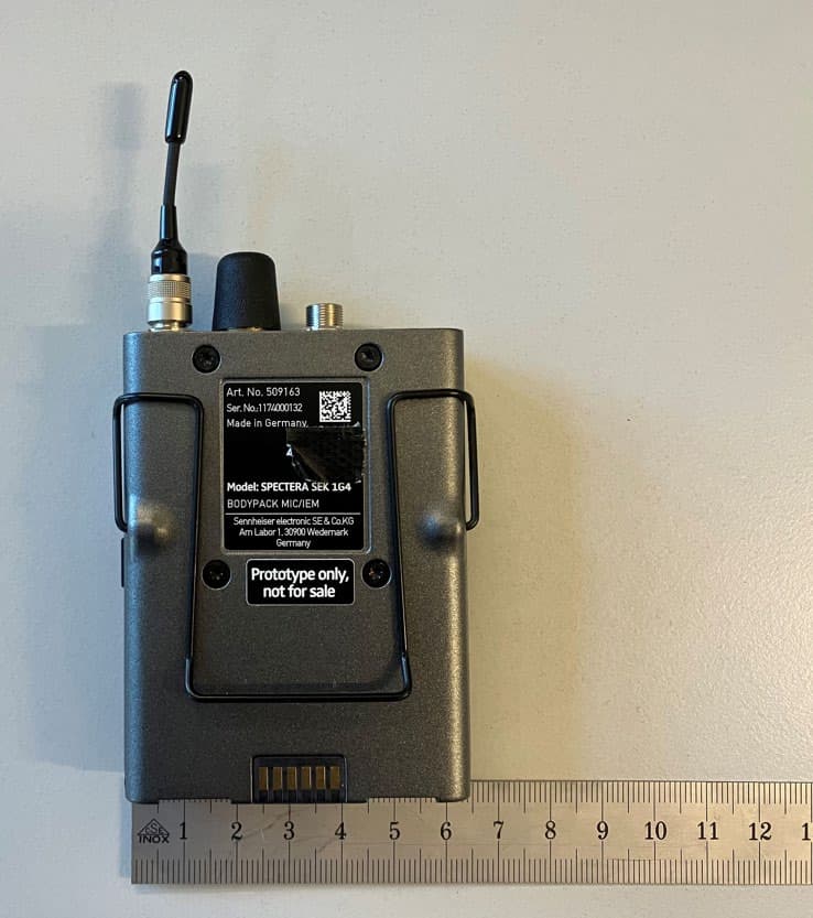
DMOSEK1G4
Mar 11, 2026Bodypack Mic/IEM
Equipment Class
TLD - Licensed LPAS Device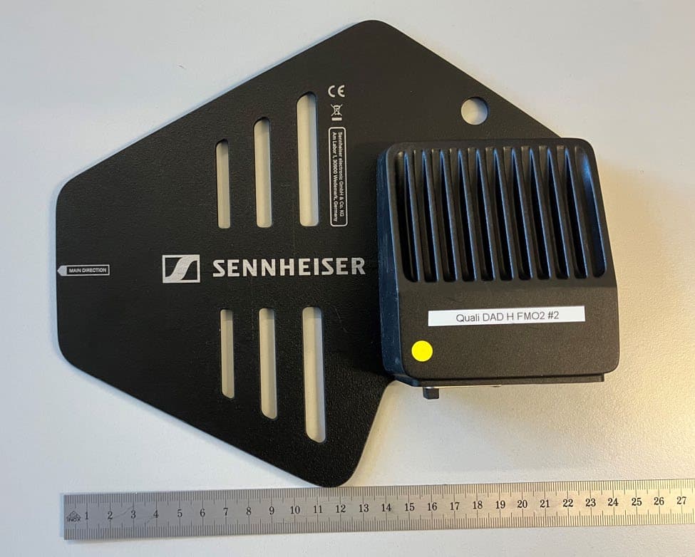
DMODAD1G4
Mar 11, 2026Antenna Transceiver
Equipment Class
TLD - Licensed LPAS DeviceDMOTSEWDX
Jan 30, 2024Wireless Table Stand
Equipment Class
TLD - Licensed LPAS Device