DMOMCR1G9Multi-Channel Receiver
Sennheiser Electronic Corp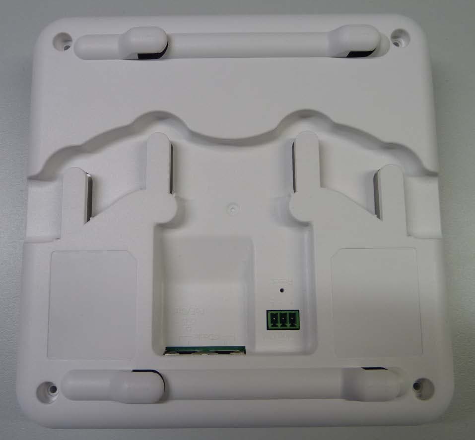
Click to zoom
Application Details
- Equipment Class
- PUB - Part 15 Unlicensed PCS Base Station
- Date of Grant
- Mar 11, 2020
- Application Purpose
- Original Equipment
- Date of Application
- Mar 11, 2020
- Equipment Note
- Multi-Channel Receiver
- Frequency Range
- 1921.53600000 - 1928.44800000
- Company
- Sennheiser Electronic Corp
- Country
- United States
Documents & Files
Document Text
Text extracted from the exhibit documents filed with the FCC. Open a document above to read the original.
Users Manual
SL MCR DW 2 SL MCR DW Product overview and operating elements ► 1Status LEDs • See „Meaning of the status LEDs“ 2Analog Out 3-pin socket • Analog audio output (see „Connecting the receiver“) • Suitable for Phoenix Contact MCVW 1.5-3-ST-3.81 3Reset button • To restore the factory settings •Hold for 5 seconds 4Dante I RJ-45 socket • Digital audio output (see „Connecting the receiver“) 5Dante II / PoE / Ctrl RJ-45 socket • Digital audio output (see „Connecting the receiver“) • PoE supply (Power over Ethernet) (see „Putting the receiver into op- eration“) • Configuration via the software or a media control system (see „Con- trolling and monitoring the receiver via the network“) Analog Out PoE/ Ctrl Reset 123 45 FrontBack SL MCR DW 3 Connecting the receiver The receiver can output analog and digital audio signals. The analog audio signal is output via the 3-pin Analog Out terminal. Digital audio signals are output via the Dante interface with two RJ-45 sockets. This interface is also used for control and configuration via the network and for Power over Ethernet supply. The following variants are possible: ► PoE / network control digital audio PoE / network control digital audiodigital audio PoE / network control digital audio Variant 1Variant 2Variant 3 SL MCR DW 4 Connecting to the network (power supply and configuration) The PoE/Ctrl RJ-45 socket (Dante I) is used to both power the receiver via Power over Ethernet and configure it using the Sennheiser Control Cock- pit software (see „Controlling and monitoring the receiver via the net- work“). ▷In your network you can either use a switch that provides PoE or a PoE injector. ► Analog Out PoE/Ctrl Reset PoE Analog Out PoE/Ctrl Reset PoE/Ctrl Control Cockpit clients optional optional Control Cockpit host PC (opt. client) Media control client LAN Application example: LAN or WiFi Media control server LAN or WiFi SL MCR DW 5 Outputting digital audio signals The Dante™ interface with two RJ-45 sockets, Dante I and Dante II, is used for outputting digital audio signals. The interface supports redundant out- put. ► Outputting analog audio signals Use the Analog Out socket to output analog audio signals. ► Analog Out PoE/Ctrl Reset Analog Out PoE/Ctrl Reset PoE/Ctrl Dante™ DSP PriSec PoE LAN LAN Application example: Analog Out Analog Out PoE/Ctrl Reset Analog Out Reset suitable for Phoenix Contact MCVW 1.5-3-ST-3.81 SL MCR DW 6 Mounting the receiver Safety instructions for installation Observe the following safety instructions when installing the product. ▷The physical mounting and all electrical installations must be per- formed by a specialist. ▷The specialist must have sufficient professional training, experience and knowledge of applicable provisions, regulations and standards to be able to properly assess the work assigned to them, identify possible hazards and take appropriate safety measures. ▷When mounting the product, observe and follow all local, national and international regulations and standards. The receiver can be mounted in the following ways. Mounting the receiver on the wall To mount the receiver on the wall, you will need the mounting frame sup- plied. Screws and anchors for mounting the product to the wall are not in- cluded with delivery. Use screws and anchors that are appropriate for the particular characteristics of your wall. ► center line cente r line top center line wal l mou nt VESA 100 cent er line >1,5 m>1.5 m>1,5 m>1,5 m SL MCR DW 7 ▷Use the included drilling template to mark the drill holes for wall mounting. ▷Maintain a minimum distance of 1.5 m from other walls and the ceiling. ▷Screw the mounting frame to the wall using four suitable screws and anchors. ► ▷Make sure that the mounting frame is aligned correctly. The top marking on the mounting frame must not point downwards. Otherwise the receiver may fall out and be damaged. ► ▷Insert the receiver into the mounting frame as shown until you hear it click into place. top center line wall mount VESA 100 center line top! top center line wall mount VES A 100 center line top! top center line wall mount VESA 100 center line top! top center line wall mount VESA 100 center line top! top center line wall mount VESA 100 center line SL MCR DW 8 Mounting the receiver on the ceiling To mount the receiver on the ceiling, you will need the mounting frame sup- plied. Screws and anchors for mounting the product to the ceiling are not included with delivery. Use screws and anchors that are appropri- ate for the particular characteristics of your ceiling. ► ▷Use the included drilling template to mark the drill holes for ceiling mounting. ▷Maintain a minimum distance of 1.5 m from the walls. ▷Screw the mounting frame to the ceiling using four suitable screws and anchors. center line center line top cente r line wa ll mount VESA 100 cent er line >1,5 m >1,5 m >1.5 m >1.5 m >1,5 m >1,5 m >1,5 m >1,5 m SL MCR DW 9 ► ▷Insert the receiver into the mounting frame as shown until you hear it click into place. top center line wall mount VESA 100 center line SL MCR DW 10 Mounting the receiver on a stand The thread in the middle of the mounting frame is suitable for mounting on a standard microphone stand with 3/8" thread. ▷Screw the mounting frame onto the microphone stand as shown. ▷Insert the receiver into the mounting frame as shown until you hear it click into place. ► top center line wall mount VESA 100 center line SL MCR DW 11 Mounting the receiver on a VESA mount The holes in the mounting frame are positioned 100 mm apart so that the mounting frame can be mounted on any VESA 100 mount. ▷Screw the mounting frame onto the VESA mount as shown using four suitable screws. ▷Insert the receiver into the mounting frame as shown until you hear it click into place. ► top center line wall mount VESA 100 center line top center line wall mount VESA 100 center line * *Example of a VESA 100 mount SL MCR DW 12 Putting the receiver into operation The receiver is powered using Power over Ethernet. As soon a…
Text truncated - open the document above for the full version.
Users Manual
Sennheiser electronic GmbH & Co. KG Am Labor 1, 30900 Wedemark, Germany www.sennheiser.com Printed in Germany, Publ. 01/20, 583940/A01 Quick Guide Kurzanleitung Guide de démarrage rapide Guida rapida Instrucciones resumidas Instruções resumidas Beknopte gebruiksaanwijzing Krótka instrukcja obsługi Snabbguide Kort vejledning Pikaohje Γρήγορος οδηγός Kısa Kılavuz Краткая инструкция 퀵 가이드 SpeechLine Digital Wireless SL MCR DW Sennheiser Documentation App or online at www.sennheiser.com/download SpeechLine Digital Wireless_ In the box Wall Cable Routing Connecting top center line wall mount VESA 100 center line top center line wall mount VESA 100 center line >1,5 m center line center line Network Control via Sennheiser Control Cockpit www.sennheiser.com/control-cockpit-software Analog Out PoE/Ctrl Reset Analog Audio: Phoenix Contact MCVW 1.5-3-ST-3.81 *not included * * Digital Audio Network Control Power over Ethernet Dante I Digital AudioDante II : : Analog Out PoE/Ctrl Reset Analog Out PoE/Ctrl Reset Analog Out PoE/Ctrl Reset OR Analog Out PoE/Ctrl Reset Configuration via Audinate Dante Controller | www.audinate.com center line center line top center line wall m ount VESA 100 center line 1 23 top center line wall mount VESA 100 center line top! top center line wall mount VESA 100 center line top! top center line wall mount VESA 100 center line top! top center line wall mount VESA 100 center line top! PoE / network control digital audio Single Cable Mode (Factory Default) Audio Redundancy ModeSplit Mode PoE / network control digital audio daisy chaindigital audio PoE / network control digital audio 583940_0120_A01_QG_SL_MCR_DW_PRT_draft03 SD.pdf 1 29.11.2019 07:53:55
Users Manual
Sennheiser electronic GmbH & Co. KG Am Labor 1, 30900 Wedemark, Germany www.sennheiser.com Printed in Germany, Publ. 01/20, 583942/A01 Technische Daten & Herstellererklärungen Specifications & Manufacturer declarations Caractéristiques techniques & Déclarations du fabricant Dati tecnici & Dichiarazioni del costruttore Especificaciones técnicas & Declaraciones del fabricante Teknik Bilgiler & Üretici Beyanları Dados técnicos & Declarações do fabricante Technische specificaties & Verklaringen van de fabrikant Dane techniczne & Deklaracje producenta Tekniska data & Tillverkarintyg Tekniske data & Producenterklæringer Tekniset tiedot & Valmistajan vakuutukset Τεχνικ ά χ αρακτηριστικά & Δηλώσεις κατασκευαστή Технические харак теристики & Заявления изготовителя 技术参数 & 制造商声明 技術仕様 & 製造者宣言 기술 데이터 & 제조사 선언 Sennheiser Documentation App or online at www.sennheiser.com/download SpeechLine Digital Wireless_ SL MCR DW SpeechLine Digital Wireless To make a claim under this warranty, contact Sennheiser Technical Services and Spare Parts Sales c/o Linfox, Gate 3, 1 Fox Lane, Erskine Park, 2759, NSW Australia Phone: (02) 9910 6700, email: [email protected] All expenses of claiming the warranty will be borne by the person making the claim. The Sennheiser International Warranty is provided by Senn- heiser Australia Pty Ltd (ABN 68 165 388 312), Level 14, To- wer A Zenith Building, 821 Pacific Highway, Chatswood NSW 2067, Australia. In compliance with the following requirements WEEE Directive (2012/19/EU) Notes on disposal The symbol of the crossed-out wheeled bin (imprint avai- lable depending on national requirements) on the product, the battery/rechargeable battery (if applicable) and/or the packaging indicates that these products must be disposed of separately at the end of their operational lifetime in accor- dance with the national legislation. For packaging disposal, please observe the legal regulations on waste segregation applicable in your country. The separate collection of waste electrical and electronic equipment, batteries/rechargeable batteries (if applicable) and packagings is used to promote the reuse and recycling and to prevent negative effects caused by e.g. potentially ha- zardous substances contained in these products. Herewith you make an important contribution to the protection of the environment and public health. EU Declaration of conformity • RoHS Directive (2011/65/EU) Hereby, Sennheiser electronic GmbH & Co. KG declares that the radio equipment type SL MCR DW is in compliance with Directive 2014/53/EU. The full text of the EU declaration of conformity is available at the following internet address: www.sennheiser.com/download Statements regarding FCC and Industry Canada This device complies with Part 15 of the FCC Rules and with Industry Canada license-exempt RSS standard(s). Operation is subject to the following two conditions: (1) this device may not cause harmful interference, and (2) this device must ac- cept any interference received, including interference that may cause undesired operation. This equipment has been tested and found to comply with the limits for a Class B digital device, pursuant to part 15 of the FCC Rules. These limits are designed to provide reason- able protection against harmful interference in a residential installation. This equipment generates, uses and can radia- te radio frequency energy and, if not installed and used in accordance with the instructions, may cause harmful inter- ference to radio communications. However, there is no gu- arantee that interference will not occur in a particular ins- tallation. If this equipment does cause harmful interference to radio or television reception, which can be determined by turning the equipment off and on, the user is encouraged to try to correct the interference by one or more of the following measures: • Reorient or relocate the receiving antenna. • Increase the separation between the equipment and receiver. • Connect the equipment into an outlet on a circuit diffe- rent from that to which the receiver is connected. • Consult the dealer or an experienced radio/ TV techni- cian for help. This Class B digital apparatus complies with the Canadian ICES-003. Changes or modifications not expressly approved by Senn- heiser electronic Corp. could void the user’s authority to operate the equipment. Radiofrequency radiation exposure Information This equipment complies with FCC and IC radiation expo- sure limits set forth for an uncontrolled environment. This equipment should be installed and operated with minimum distance of 20 cm between the radiator and your body. FR Déclarations du fabricant Garantie Sennheiser electronic GmbH & Co. KG offre une garantie de 24 mois sur ce produit. Pour avoir les conditions de garantie actuelles, veuillez vi- siter notre site web sur www.sennheiser.com ou contactez votre partenaire Sennheiser. En conformité avec les exigences suivantes Directive DEEE (2012/19/UE) Notes sur la gestion de fin de vie Le symbole de la poubelle sur roues barrée d‘une croix (im- pression disponible selon les directives nationales) sur le produit, la pile/batterie (le cas échéant) et/ou l‘emballage signifie que ces produits, arrivés en fin de vie, doivent fai- re l‘objet d‘une collecte séparée en respectant la législation nationale. Pour les déchets d‘emballages, veuillez respecter les lois applicables dans votre pays en matière de tri sélectif des déchets. L‘objectif principal de la collecte séparée des déchets d‘équi- pements électriques et électroniques, des piles/batteries (le cas échéant) et des emballages est de promouvoir le réemploi et/ou le recyclage et de prévenir les effets négatifs sur la santé et l‘environnement dus à des polluants potenti- ellement contenus. Vous contribuerez ainsi à la préservation de l‘environnement et à la protection de la santé. Déclaration UE de conformité • Directive RoHS (2011/65/UE) Le soussigné, Sennheiser electronic GmbH & Co. KG, décla- re que l‘équipem…
Text truncated - open the document above for the full version.
External Photos
Test report no.: 1-3753/17-01-06 2020-01-08 Page 3 of 6 Annex B: External Photographs of the EUT Photo 1: Photo 2:
Internal Photos
Test report no.: 1-3753/17-01-06 2020-01-08 Page 4 of 6 Annex C: Internal Photographs of the EUT Photo 1: Photo 2: Test report no.: 1-3753/17-01-06 2020-01-08 Page 5 of 6 Photo 3: Photo 4: Test report no.: 1-3753/17-01-06 2020-01-08 Page 6 of 6 Photo 5:
RF Exposure Info
© CTC advanced GmbH Page 1 of 3 D-PL-12076-01-03 Maximum Permissible Exposure (MPE) & Exposure evaluation Report identification number: 1-8380/19-01-04 MPE (FCC_ISED) Certification numbers and labeling requirements FCC ID DMOMCR1G9 ISED number 2099A-MCR1G9 HVIN (Hardware Version Identification Number) SL MCR DW PMN (Product Marketing Name) SL MCR DW FVIN (Firmware Version Identification Number) -/- HMN (Host Marketing Name) -/- This report is electronically signed and valid without handwriting signature. For verification of the electronic signatures, the public keys can be requested at the testing laboratory. Document authorised: Alexander Hnatovskiy Marco Scigliano Lab Manager Testing Manager Radio Communications & EMC Radio Communications & EMC Report no.: 1-8380/19-01-04 © CTC advanced GmbH Page 2 of 3 EUT technologies: Technologies: Max. declared PEAK - EIRP: Max. declared AVG - EIRP: UPCS 1925 MHz (Proprietary) 18.0 to 21.0 dBm 13.2 dBm Note: The device has up to 4 of the above described declared DECT transceiver transmitting at the same time, but all sending in different time slots, that leads to a Duty Cycle of 4/24 (17%). Prediction of MPE limit at given distance - FCC Equation from page 18 of OET Bulletin 65, Edition 97-01 S = PG / 4 π R 2 where: S = Power density P = Power input to the antenna G = Antenna gain R = Distance to the center of radiation of the antenna PG = Output Power including antenna gain The table below is excerpted from Table 1B of 47 CFR 1.1310 titled “Limits for Maximum Permissible Exposure (MPE), Limits for General Population/Uncontrolled Exposure” Frequency Range (MHz) Power Density (mW/cm 2 ) Averaging Time (minutes) 300 -1500 f/1500 30 1500 - 100000 1.0 30 where f = Frequency (MHz) Prediction: worst case Technologies:UPCS Frequency (MHz)1925 PGDeclared max power (EIRP)13.2dBm R Distance20cm SMPE limit for uncontrolled exposure1 mW/cm 2 Calculated Power density:0.0042mW/cm² Calculated percentage of Limit: 0.42% This prediction demonstrates the following: The power density levels for FCC at a distance of 20 cm are below the maximum levels allowed by regulations. Report no.: 1-8380/19-01-04 © CTC advanced GmbH Page 3 of 3 Prediction of MPE limit at given distance - ISED RSS-102, Issue 5, 2.5.2 RF exposure evaluation is required if the separation distance between the user and/or bystander and the device’s radiating element is greater than 20 cm, except when the device operates as follows: • below 20 MHz and the source-based, time-averaged maximum e.i.r.p. of the device is equal to or less than 1 W (adjusted for tune-up tolerance); • at or above 20 MHz and below 48 MHz and the source-based, time-averaged maximum e.i.r.p. of the device is equal to or less than 4.49/ƒ 0.5 W (adjusted for tune-up tolerance), where ƒ is in MHz; • at or above 48 MHz and below 300 MHz and the source-based, time-averaged maximum e.i.r.p. of the device is equal to or less than 0.6 W (adjusted for tune-up tolerance); • at or above 300 MHz and below 6 GHz and the source-based, time-averaged maximum e.i.r.p. of the device is equal to or less than 1.31 x 10 -2 ƒ 0.6834 W (adjusted for tune-up tolerance), where ƒ is in MHz; • at or above 6 GHz and the source-based, time-averaged maximum e.i.r.p. of the device is equal to or less than 5 W (adjusted for tune-up tolerance). Prediction: worst case UPCS Frequency1925MHz RDistance20cm PG Maximum EIRP13.2dBm PG Maximum EIRP20.9mW Exclusion Limit from above:2.30W Calculated percentage of Limit: 0.91% Conclusion: RF exposure evaluation is not required.
Test Report
2020-03-09 Page 1 of 60 TEST REPORT Test Report No.: 1-8380/19-01-06 Testing Laboratory Applicant CTC advanced GmbH Untertürkheimer Straße 6 – 10 66117 Saarbrücken/Germany Phone: + 49 681 5 98 - 0 Fax: + 49 681 5 98 - 9075 Internet: http://www.ctcadvanced.com e-mail: [email protected] Accredited Test Laboratory: The testing laboratory (FCC part 15 D) is accredited according to DIN EN ISO/IEC 17025 (2005) by the Deutsche Akkreditierungsstelle GmbH (DAkkS) The accreditation is valid for the scope of testing procedures as stated in the accreditation certificate with the registration number: D-PL-12076-01-04 / -05 Sennheiser electronic GmbH & Co. KG Am Labor 1 30900 Wedemark Germany Contact: Nils Knauer e-mail: [email protected] Phone: +49 5130/600-9524 Manufacturer Sennheiser electronic GmbH & Co. KG Am Labor 1 30900 Wedemark Germany Test Standard/s FCC Part 15, subpart D: 2016 Isochronous UPCS Device 1920 – 1930 MHz Industry Canada RSS-213, Issue 3: 2015 2 GHz Licence-exempt Personal Communication Service Devices (LE-PCS) Test Item Kind of product: Multi-Channel Receiver Product name: SL MCR DW HVIN: PMN: FVIN: HMN: FCC ID: SL MCR DW SL MCR DW / / DMOMCR1G9 IC: 2099A-MCR1G9 S/N serial number: Radiated: / Conducted: / HW hardware status: v6rB SW software status: BR 0.5-45, smcr 0.9.3-6, mix v0012, SoC 02.10 Frequency [MHz]: 1920 -1930 Type of Modulation: Digital (Gaussian Frequency Shift Keying) Number of channels: 5 RF Channels, 5x12 = 60 TDMA Duplex Channels Antenna: 8 internal antennas Power Supply: POE powered Temperature Range: -20°C to 50°C Test Report authorised: Test performed: 2020-03-09 Lenjoint, Marco 2020-03-09 Wolf, Joachim Lab Manager RCE Head of Department EPNS Test report no.: 1-8380/19-01-06 2020-03-09 Page 2 of 60 1 Table of contents 1 Table of contents ......................................................................................................................................... 2 2 General information .................................................................................................................................... 4 2.1 Notes and disclaimer ....................................................................................................................... 4 2.2 Application details ........................................................................................................................... 4 3 Test standard/s: ........................................................................................................................................... 4 4 Test Environment ........................................................................................................................................ 5 5 Summary of Measurement Results ........................................................................................................... 6 6 Test Set-up ................................................................................................................................................... 7 6.1 Frequency Measurements ............................................................................................................... 7 6.2 Timing Measurements ..................................................................................................................... 7 6.3 Conducted Emission Test ............................................................................................................... 7 6.4 Radiated Emission Test ................................................................................................................... 8 6.5 Power Line Conducted Emissions Test ....................................................................................... 10 6.6 Monitoring Tests............................................................................................................................. 11 6.7 Radiated Output Power Test ......................................................................................................... 11 7 Detailed Test Results ................................................................................................................................ 12 7.1 Power Line Conducted Emissions ............................................................................................... 12 7.2 Digital Modulation Techniques ..................................................................................................... 15 7.3 Labeling Requirements .................................................................................................................. 15 7.4 Antenna Requirements .................................................................................................................. 16 7.5 Channel Frequencies ..................................................................................................................... 16 7.6 Automatic Discontinuation of Transmission ............................................................................... 17 7.7 Peak Power Output ........................................................................................................................ 18 7.8 Emission Bandwidth B ........................................................................................................... 22 7.9 Power Spectral Density ................................................................................................................. 25 7.10 In-Band Unwanted Emissions, Conducted .............................................................................. 28 7.11 Out-of-Band Emissions, Conducted ......................................................................................... 31 7.12 Carrier Frequency Stability ........................................................................................................ 35 7.13 Frame Repetition Stability ......................................................................................................... 36 7.14 Frame Period and J…
Text truncated - open the document above for the full version.
Test Setup Photos
2020-01-08 Page 1 of 6 Annex A: Photographs of the Test Set- up Photo 1: Radiated Emission Photo 2: Radiated Emission Test report no.: 1-3753/17-01-06 2020-01-08 Page 2 of 6 Photo 3: Conducted Emission
Contact Information
Applicant
Michael Lieske
Test Firm
cetecom advanced GmbHGerald Schmidt
Technical Specifications
| # | Rule Parts | Frequency Range | Power Output | Tolerance |
|---|---|---|---|---|
| 1 | 15D | 1.92 GHz - 1.93 GHz | 19.00 mW | 4.2000000000 ppm |
Other Applications from Sennheiser Electronic Corp
DMOSKM1G4
Aug 19, 2026Handheld Transmitter
Equipment Class
TLD - Licensed LPAS DeviceDMOSKMUHF
May 20, 2026Antenna Transceiver
Equipment Class
DWM - Part 15 Wireless Microphone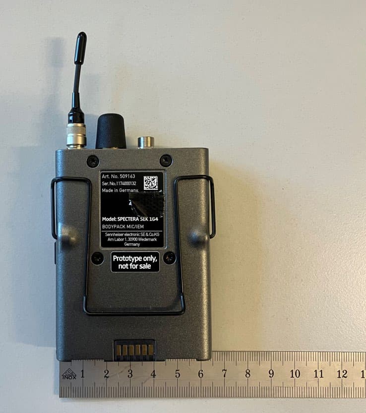
DMOSEK1G4
Mar 11, 2026Bodypack Mic/IEM
Equipment Class
TLD - Licensed LPAS Device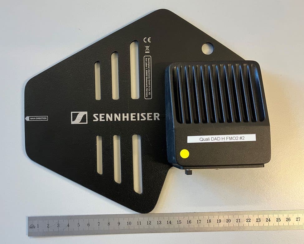
DMODAD1G4
Mar 11, 2026Antenna Transceiver
Equipment Class
TLD - Licensed LPAS DeviceDMOTSEWDX
Jan 30, 2024Wireless Table Stand
Equipment Class
TLD - Licensed LPAS Device