DMORS99SAFM Wireless Stereo TX
Sennheiser Electronic Corp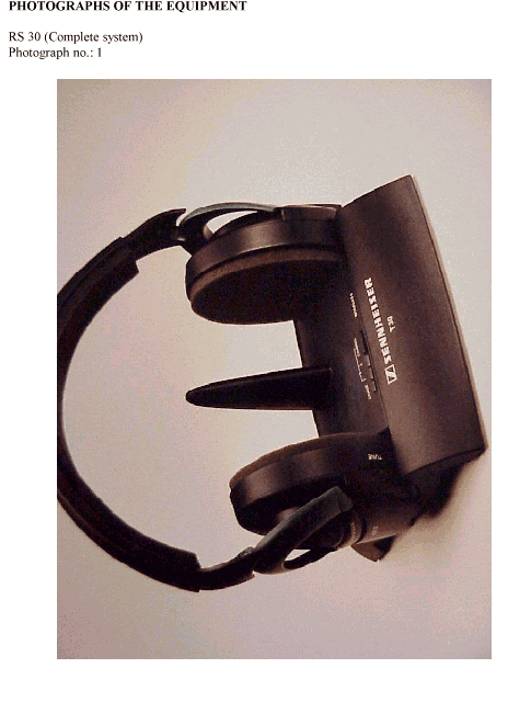
Click to zoom
Application Details
- Equipment Class
- DXX - Part 15 Low Power Communication Device Transmitter
- Date of Grant
- Feb 22, 2000
- Application Purpose
- Original Equipment
- Date of Application
- Dec 26, 1999
- Equipment Note
- FM Wireless Stereo TX
- Frequency Range
- 926.50000000 - 926.50000000
- Company
- Sennheiser Electronic Corp
- Country
- United States
Documents & Files
Document Text
Text extracted from the exhibit documents filed with the FCC. Open a document above to read the original.
Users Manual
WIRELESS RS 80-7 English WIRELESS RS 80 Thank you for choosing Sennheiser! Over half a century of accumulated expertise in the desi gn and manufacture of high-quality electro-acoustic equipment have made Sennheiser a world-leadin g company in this field. We have designed this product to give you reliable operation over many years. Please take a few moments to read these instructions carefull y, as we want you to en joy your new Sennheiser product quickly and to the full. SYSTEM COMPONENTS AND CONNECTIONS Before proceeding, please check and make sure the s ystem components shown are all present and correct (see illustration inside cover page). Establish the necessar y connections. Char ge the accupack for 24 hours before you use it for the first time! (please refer to the section Charging the Accu pack) WHERE TO PLACE THE TRANSMITTER Choose a suitable place near your hi-fi system or TV set. Do not place the transmitter close to metal objects such as shelf bars, reinforced concrete walls, etc. The transmitter features a convenient automatic on/ off function, i.e. it is switched on or off via the audio si gnal from the sound source. The transmitter’s char ging function is independent of the automatic on/off function. Accupacks can alwa ys be recharged when the transmitter is connected to the mains. SWITCHING THE HEADPHONE RECEIVER ON The O N /O FF switch is on the right earpiece. SWITCHING THE HEADPHONE RECEIVER OFF Make sure to switch off the head phones after each use and store the head phones in the transmitter’s char ging compartment to avoid discharging the accu pack. Bild mit Uhr Bild mit Aufstellort einfügen Bild mit EIN / AUS am Hörer einfügen WIRELESS RS 80-8 English ADJUSTING THE VOLUME Set the volume of your sound source to a medium value. With some devices, the volume for the head phone output can be regulated separately. Use the V OLUME control on the right earpiece to ad just the headphones ́ volume. ADJUSTING THE RECEIVER CHANNEL Turn the T UNE control on the earpiece until you can hear the audio si gnal loud and clear. CHANGING THE TRANSMISSION CHANNEL To avoid interference caused b y the simultaneous o peration of several transmitters, select a different channel on each transmitter. De pending on the s ystem variant, two or three switchable transmission channels are available. To select a channel, press the C HANNEL button until the desired LED or LED combination li ghts up: LED 1channel 1 active LED 2channel 2 active LED 1 and 2channel 3 active (except 863 MHz version) COMPLETE FREEDOM OF MOVEMENT It is not necessar y that transmitter and headphone receiver are in a direct line of si ght, so you can move around freel y in the home or outside in the garden. One transmitter can be used to transmit to several receivers on the same fre quency. Additional head phones with the designation HDR 80 are available from your specialist dealer. Please make sure to choose head phones with the same fre quency range as the transmitter you are using (see type plate on the bottom of the transmitter). Doppel-Bild mit Lautst. Hörer und Tonqle einfügen Bild mit Tuning am Hörer einfügen Bild mit Tanzmännchen einfügen Bild von Verpackung einfügen WIRELESS RS 80-9 English CHARGING THE ACCUPACK For char ging the accupack, place the headphones into the transmitter’s char ging compartment (nb: make sure the head phones are inserted the correct wa y round. The Sennheiser logo on the headband must be readable lookin g from the front - see dia gram. The charging contacts are on the RH ear piece of the headphones - these are placed on the corres ponding contacts in the LH indentation of the transmitter, the one next to the “char ge” light). The red LED on the transmitter must li ght up to show charging is taking place. Alwa ys store the headphones on the transmitter to ensure that they are fully char ged when they are needed. The headphones are automatically switched off by the char ging process. BA 151 SPARE ACCUPACK When the head phones’ accupack is going flat (noise, interference and distortion are sure si gns of a flat accupack), recharge the accupack. After an initial charging of 24 hours, the normal char ging time is 14 hours. A fully charged accupack has an o perating time of approx. four hours. Place the discharged accupack in the charging com partment at the back of the transmitter and use the spare accupack in the meantime. Additional BA 151 s pare accupacks can be charged via the L 151-2 charger (available from your specialist dealer). Before dis posing of an old and exhausted accupack, make sure that it is totally dischar ged by using it until the device switches off. To protect the environment, only dis pose of totally exhausted accupacks. HiD yn plus ® This device is e quipped with HiDyn plus ® , Sennheiser ́s noise reduction system that reduces noise and interference in wireless transmission s ystems. ADDITIONAL INFORMATION The audio transmission technolo gy used with this device is basically that of a radio. Accordin g to today’s scientific knowledge, the radio waves emitted by this device are not harmful to humans or animals. ATTENTION: LISTENING AT HIGH VOLUME LEVELS FOR LONG PERIODS CAN PERMANENTLY DAMAGE YOUR HEARING. This device has been desi gned for use with stereo devices. For connection to mono devices, please use a stereo to mono jack plug available from most audio accessory sho ps. Use a soft cloth or, if necessar y, a damp wash-leather for cleaning the devices. Do not use a ggressive cleansing agents. Hörerauf Station einfügen WIRELESS RS 80-10 English Varnish or furniture polish may attack the rubber feet of the transmitter’s charging unit. As these could stain your furniture, place the transmitter on a non-slip pad. IF PROBLEMS OCCUR ... Are all connections properly made? Are the head phones and sound source switched on and is the volume correctl y adjusted? Have you charged the accupack for at least 20 minutes? Are you too far from the transmitter? (if so, move closer) Cho…
Text truncated - open the document above for the full version.
Users Manual
Wireless RS 30 A1) Stellen Sie die Steckverbindungen her. A2 ) Laden Sie den Akku vor dem ersten Betrieb für 24 Stunden. B1 ) Stecken Sie den Akku in den Schacht am Hörer. B2 ) Schalten Sie den Kopfhörer an der rechten Ohrmuschel auf O N . B3 ) Drehen Sie den Regler T UNE an der rechten Ohrmuschel, bis Sie einen klaren Ton em pfangen. Wechseln Sie bei Empfangsüber- schneidun gen den Sendekanal und stellen Sie den Empfang am Ko pfhörer neu ein. B4 ) Stellen Sie die Lautstärke am Hörer und an der Tonquelle ein. B5 ) Schalten Sie den Hörer aus. Stecken Sie den Akku zum Laden in den Schacht am Sender. Die rote LED muß leuchten. A1 ) Establish the necessary connections. A2 ) Charge the accupack for 24 hours before you use it for the first time! B1 ) Insert the accupack into the battery compartment on the headphones. B2 ) Switch on the headphones by setting the switch on the right earpiece to ON. B3 ) Turn the TUNE control on the right earpiece until you can hear the audio si gnal loud and clear. If interference is present, select a different transmission channel and set the head phones to the res pective frequency. B4 ) Adjust the volume of headphones and sound source. B5 ) Switch off the headphones. For charging the accupack, insert it into the char ging compartment on the transmitter. The red LED must li ght up. A1 ) Procédez aux raccordements utiles. A2 ) Mettre en charge le pack d'accus pendant 24 heures avant toute première utilisation! B1 ) Insérez le pack d'accus dans le compartiment prévu à cet effet sur le cas que. B2 ) Mettre en marche le casque en positionnant sur ON le commutateur placé sur l'écouteur droit. B3 ) Tourner le contrôle marqué T UNE situé sur l'écouteur jusqu'à ce que le si gnal audio soit fort et clair. En cas d'interférence venant perturber la réce ption, sélectionner un canal de transmission différent et régler le cas que sur la même fréquence. B4 ) Ajustez le volume du casque et celui de la source sonore. B5 ) Commuter le casque sur "off". Pour charger le pack d'accus, insérez-le dans le com partiment prévu sur l'émetteur. La LED rouge doit s'allumer. A1 ) Eseguite i collegamenti. A2 ) Caricate l’accumulatore per 24 ore prima del primo utilizzo. B1 ) Inserite l’accumulatore nell’apposito vano sull’auricolare. B2 ) Posizionate l’interruttore sull’auricolare destro su O N . B3 ) Ruotate il regolatore T UNE sull’auricolare destro finché ricevete un suono chiaro. In caso di disturbi di ricezione cambiate il canale di trasmissione e re golate la ricezione del segnale nella cuffia. B4 ) Regolate il volume della cuffia e della fonte sonora. B5 ) Spegnete la cuffia. Inserite l’accumulatore nel vano di ricarica posizionato sul trasmettitore per la ricarica. Il LED rosso deve essere illuminato. A1 ) Conecte las conexiones. A2 ) Antes de utilizar el aparato por primera vez, cargue la batería durante 24 horas. B1 ) Coloque la batería en el compartimento situado en los auriculares. B2 ) Conecte los auriculares poniendo en O N , el botón situado en el auricular derecho. B3 ) Gire el regulador T UNE situado en el auricular derecho, hasta que reciba un sonido nítido. Si se produjeran interferencias en la rece pción, cambie el canal emisor y reestablezca la recepción. B4 ) Ajuste el volumen en los auriculares y en la fuente de sonido. B5 ) Desconecte los auriculares. Coloque la batería en el compartimento situado en la estación emisora, para que se cargue de nuevo. La luz ro ja, LED, deberá permanecer encendida. A1 ) Sluit de stekkerverbindingen aan. A2 ) Laad de accu voor de eerste inbedrijfstelling 24 uren lang op. B1 ) Steek de accu in de schacht van de hoofdtelefoon. B2 ) Zet de hoofdtelefoon op de rechter oorschelp op O N . B3 ) Draai de regelaar T UNE op de rechter oorschelp totdat u een duidelijk si gnaal ontvangt. Wijzig in het geval van een ontvangstoverlapping het zendkanaal en stel de ontvan gst op de hoofdtelefoon nog een keer in. B4 ) Stel het volume aan de hoofdtelefoon en geluidsbron in. B5 ) Schakel de hoofdtelefoon uit. Steek de accu in de schacht van de hoofdtelefoon om hem o p te laden. De rode LED moet lichten. DEUTSCH ENGLISH FRANÇAIS ITALIANO ESPAÑOL NEDERLANDS Wireless RS 30 A1) Stellen Sie die Steckverbindungen her. A2 ) Laden Sie den Akku vor dem ersten Betrieb für 24 Stunden. B1 ) Stecken Sie den Akku in den Schacht am Hörer. B2 ) Schalten Sie den Kopfhörer an der rechten Ohrmuschel auf O N . B3 ) Drehen Sie den Regler T UNE an der rechten Ohrmuschel, bis Sie einen klaren Ton em pfangen. Wechseln Sie bei Empfangsüber- schneidun gen den Sendekanal und stellen Sie den Empfang am Ko pfhörer neu ein. B4 ) Stellen Sie die Lautstärke am Hörer und an der Tonquelle ein. B5 ) Schalten Sie den Hörer aus. Stecken Sie den Akku zum Laden in den Schacht am Sender. Die rote LED muß leuchten. A1 ) Establish the necessary connections. A2 ) Charge the accupack for 24 hours before you use it for the first time! B1 ) Insert the accupack into the battery compartment on the headphones. B2 ) Switch on the headphones by setting the switch on the right earpiece to ON. B3 ) Turn the TUNE control on the right earpiece until you can hear the audio si gnal loud and clear. If interference is present, select a different transmission channel and set the head phones to the res pective frequency. B4 ) Adjust the volume of headphones and sound source. B5 ) Switch off the headphones. For charging the accupack, insert it into the char ging compartment on the transmitter. The red LED must li ght up. A1 ) Procédez aux raccordements utiles. A2 ) Mettre en charge le pack d'accus pendant 24 heures avant toute première utilisation! B1 ) Insérez le pack d'accus dans le compartiment prévu à cet effet sur le cas que. B2 ) Mettre en marche le casque en positionnant sur ON le commutateur placé sur l'écouteur droit. B3 ) Tourner le contrôle marqué T UNE situé sur l'écouteur jusqu'à ce que le si gnal audio soit fort et clair. En cas d'interférence venant perturber la réce ption, sélectionner un canal de …
Text truncated - open the document above for the full version.
Block Diagram
Audio left 38kHz FMUX LED LED LED LED Charge Display Unit RX - Charge Optional Surround Display Logic Surround & Switch Display Selector Logic Channel Modulation T60-9 only DIV 2 Oscillator Crystal Audio right ON / OFF Auto Power SupplyPower 12V - 18V DC FilterLine Block - Diagram TX99-9 Transmitter - Family Channel RF - ON / OFF Antenna RF - Output VCO 38kHz 19kHzPILOT & AGC Limiter CoderStereo Optional Circuit Surround 12kHz LP-Filter12kHz LP-Filter Compressor HI-DYN 60kHz LP-Filter Optional T80-9 only Channel ON/OFFSurroundOptional T60-9 only T60-9 only T60-9 only
Cover Letter(s)
FCC ID: DMORS99SA Federal Communications Commission 7435 Oakland Mills Road Columbia, MD 21045 Authority to Act as Agent to the Federal Communications Commission On our behalf, I appoint Cetecom to act as agent in the preparation of this application for equipment authorization to the Federal Communications Commission. I certify that submitted Exhibits properly describe the device or system for which equipment authorization is sought. I also certify that each unit manufactured, imported or marketed, as defined in the Commission’s regulations will have affixed to it a label identical to that submitted for approval with this application. Dated this 15th day of December, 1999 Agency agreement expiration date: June 15, 2000 By: Name:Uwe Sattler Title:Technical Director Telephone:860-434-9190 Ext. 128 Applicant:Sennheiser Electronic Corp. Grantee Code:DMO Sennheiser Electronic Corporation 1 Enterprise Drive Old Lyme, CT 06371 Tel. 860-434-9190, Fax 860-434-1759 www.sennheiserusa.com
Cover Letter(s)
SENNHEISER APPLICATION FOR WIRELESS MICROPHONE SYSTEM Application filed for certification under Section 15.249 of the FCC Rules The Sennheiser application is requesting certification of a product family consisting of Models RS 30, RS 40, RS 60, and RS 80. They use identical transmitter output circuitry and differ only in the features that are available from the receiver decoder circuitry, such as stereo capability, etc. Test report for the Mdls. 30, 40, and 80 have been filed showing compliance with the applicable limits. The test report for the Mdl. 60 transmission file was corrupted during transmission and was not available for filing. Due to the similarity of the units (all models use the same transmitter output circuits), it does not appear to be necessary to file the report for the Mdl. 60. However, if the reviewer judges that it is needed, I will be pleased to forward a copy to you. Phil Inglis Agent for Cetecom/Sennheiser 1/8/99
ID Label/Location Info
REVISED THAT LABEL WILL BE ATTACHED TO THE TRANSMITTER PER FCC REQUEST: Below is the drawing of the revised FCC ID label. This Label will be located on the bottom of the transmitter unit in the location as shown on the label location photo. FCC ID: DMORS99SA This device complies with Part 15 of the FCC Rules. Operation is subject to the following two conditions: (1) this device may not cause harmful interference, and (2) this device must accept any interference received, including interference that may cause undesired operation. Sennheiser will use a label with the above language to satisfy the requirements of Section 15.19. Phillip Inglis
Test Report
CETECOM ICT Services GmbH Radio Satellite Communication Untertürkheimer Straße 6-10 . D-66117 SaarbrückenTelefon: +49 (0)681 598-9100Telefax: -9075 RSC11issue test report consist of1 PagesPage 1 (1) Test report no.: 2_1848-A/99 FCC Rule 15.249 / USA RS 30 Akkreditiertes Prüflaboratorium DAR-Registriernummer: TTI-P-G 166/98-00 vom 18.09.98 CETECOM ICT Services GmbH Test report no.: 2_1848-A/99Issue Date: 07.12.1999Page 4 (1) Table of Contents 1 General information 1.1 Notes 1.2 Testing laboratory 1.3 Details of applicant 1.4 Application details 1.5 Test item 1.6 Test standards 2 Technical test 2.1 Summary of test results 2.2 Test report 1 General information 1.1 Notes The test results of this test report relate exclusively to the test item specified in 1.5. The CETECOM ICT Services GmbH does not assume responsibility for any conclusions and generalisations drawn from the test results with regard to other specimens or samples of the type of the equipment represented by the test item. The test report may only be reproduced or published in full. Reproduction or publication of extracts from the report requires the prior written approval of the CETECOM ICT Services GmbH. CETECOM ICT Services GmbH Test report no.: 2_1848-A/99Issue Date: 07.12.1999Page 4 (1) 1.2Testing laboratory CETECOM ICT Services GmbH 66117 Saarbrücken Untertürkheimer Straße 6 - 10 Deutschland Telefone: + 49 681 598 - 9000 Telefax : + 49 681 598 - 9075 E-mail: [email protected] Internet: www.cetecom.de Accredited testing laboratory DAR-registration number : TTI-P-G-166/98-00 vom 18.09.98 1.3Details of applicant Name : Sennheiser electronic GmbH & Co. KG Street : Am Labor 1 City : D-30900 Wedemark Country : Germany Telephone: +49 (0) 5130 / 600-0 Telefax : +49 (0) 5130 / 600-324 Contact : Mr. Klaus Willemsen Telephone: +49 (0) 5130 / 600-542 1.4Application details Date of receipt of application : 06.12.99 Date of receipt of test item : 06.12.99 Date of test : 07.12.99 1.5Test item Type of equipment :Wireless headphone system Type designation:RS 30 (consists: T 30 and HDR 30) Manufacturer:applicant Street: City: Country: Serial number:-.- Additional informations:: Frequency:925, 926, 926.5 MHz / 180KF3EChannel separation:-.- kHz Number of channels :3 Antenna:integral antenna Power supply:Tx: 120V AC / 12-18V DC Rx: 2.4V NC-accu Type of equipment :- Unmodulated carrier:- 1.6Test standards: FCC Rule Part 15.249 CETECOM ICT Services GmbH Test report no.: 2_1848-A/99Issue Date: 07.12.1999Page 4 (1) 2 Technical test 2.1Summary of test results No deviations from the technical specification(s) were ascertained in the course of the tests performed. Technical responsibility for area of testing : 23.12.99RSC8411Berg M. DateSectionNameSignature 23.12.99RSC8414Ames H. DateSectionNameSignature CETECOM ICT Services GmbH Test report no.: 2_1848-A/99Issue Date: 07.12.1999Page 4 (1) 2.2Test report TEST REPORT FCC Rule Part 15.249 Test report no. : 2_1848-A/99 CETECOM ICT Services GmbH Test report no.: 2_1848-A/99Issue Date: 07.12.1999Page 4 (1) TEST REPORT REFERENCE LIST OF MEASUREMENTS SUBCLAUSEPARAMETER TO BE MEASUREDPAGE Transmitter parameters § 15.249Field strength of fundamental7 § 15.249Field strength of harmonics8 § 15.209Emissions radiated outside of the specified frequency bands9 § 15.207Conducted limits10 Receiver parameters § 15.209Spurious radiations - Radiated11 Test equipment listing12 Photographs of the equipment14 CETECOM ICT Services GmbH Test report no.: 2_1848-A/99Issue Date: 07.12.1999Page 9 (1) Equipment under test : RS 30 Ambient temperature: 23°C Relative humidity : 46% REFERENCE NUMBER(S) OF TEST EQUIPMENT USED (for reference numbers see test equipment listing) 17 - 24 FIELD STRENGTH OF FUNDAMENTIAL SUBCLAUSE § 15.249 a) Polarisation of the measurements for the larger power level .: vertical Measurement distance 3 m TEST CONDITIONSFIELD STRENGTH (mV/m ) Frequency (MHz)926.0925.0926.5 T nom ( 23 )°C V nom ( 120 )V48.647.4846.94 Maximum deviation from output power under extreme test conditions (dBc) 0.10.10.1 Measurement uncertainty±3dB LIMIT SUBCLAUSE § 15.249 a) For normal test conditions Frequency rangeField strength of fundamental (mV/m) 902 - 928 MHz50 2400 - 2483.5 MHz50 5725 - 5875 MHz50 24.0 - 24.25 GHz250 CETECOM ICT Services GmbH Test report no.: 2_1848-A/99Issue Date: 07.12.1999Page 9 (1) Equipment under test : RS 30 Ambient temperature: 23°C Relative humidity : 46% REFERENCE NUMBER(S) OF TEST EQUIPMENT USED (for reference numbers see test equipment listing) 17 - 24 FIELD STRENGTH OF HARMONICS SUBCLAUSE § 15.249 a) Polarisation of the measurements for the larger power level .: vertical Measurement distance 3 m FIELD STRENGTH OF HARMONICS 926.0 MHz925.0 MHz926.5 MHz f (MHz) DetectorLevel (μV/m) f (MHz) DetectorLevel (μV/m) f (MHz) DetectorLevel (μV/m) 1852.0Peak398.11850.0Peak386.51853.0Peak384.5 3704.0Peak354.83700.0Peak355.13706.0Peak351.2 Measurement uncertainty± 3dB LIMIT SUBCLAUSE § 15.249 a) Fundamental frequencyField strength of harmonics (μV/m) 902 - 928 MHz500 2400 - 2483.5 MHz500 5725 - 5875 MHz500 24.0 - 24.25 GHz2500 CETECOM ICT Services GmbH Test report no.: 2_1848-A/99Issue Date: 07.12.1999Page 9 (1) Equipment under test : RS 30 Ambient temperature: 23°C Relative humidity : 46% REFERENCE NUMBER(S) OF TEST EQUIPMENT USED (for reference numbers see test equipment listing) 17 - 24 EMISSIONS RADIATED OUTSIDE OF THE SPECIFIED FREQUNECY BANDS SUBCLAUSE §15.249 c) Transmitter operatingModulated/Unmodulated* *(Delete whichever is inappropriate) Measurement distance see table SPURIOUS EMISSIONS LEVEL (μV/m) 926.0 MHz925.0 MHz926.5 MHz f (MHz) DetectorLevel (μV/m) f (MHz) DetectorLevel (μV/m) f (MHz) DetectorLevel (μV/m) 1389.0Peak125.91387.5Peak124.51389.8Peak122.5 2315.0Peak158.52312.5Peak160.32316.3Peak150.7 3241.0Peak354.83237.5Peak344.83242.8Peak339.7 Measurement uncertainty± 3dB Limits SUBCLAUSE § 15.209 Frequency (MHz)Field strength (μV/m)Measurement distance (m) 0.009 - 0.4902400/F(kHz)300 …
Text truncated - open the document above for the full version.
Test Report
CETECOM ICT Services GmbH Radio Satelite Communication Untertürkheimer Straße 6-10 . D-66117 SaarbrückenTelefon: +49 (0)681 598-9100Telefax: -9075 RSC11issue test report consist of1 PagesPage 1 (1) Test report nr.: 2_1848-B/99 FCC Rule 15.249 / USA RS 40 Akkreditiertes Prüflaboratorium DAR-Registriernummer: TTI-P-G 166/98-00 vom 18.09.98 CETECOM ICT Services GmbH Test report no.: 2_1848-B/99Issue Date: 07.12.1999Page 4 (1) Table of Contents 1 General information 1.1 Notes 1.2 Testing laboratory 1.3 Details of applicant 1.4 Application details 1.5 Test item 1.6 Test standards 2 Technical test 2.1 Summary of test results 2.2 Test report 1 General information 1.1 Notes The test results of this test report relate exclusively to the test item specified in 1.5. The CETECOM ICT Services GmbH does not assume responsibility for any conclusions and generalisations drawn from the test results with regard to other specimens or samples of the type of the equipment represented by the test item. The test report may only be reproduced or published in full. Reproduction or publication of extracts from the report requires the prior written approval of the CETECOM ICT Services GmbH. CETECOM ICT Services GmbH Test report no.: 2_1848-B/99Issue Date: 07.12.1999Page 4 (1) 1.2Testing laboratory CETECOM ICT Services GmbH 66117 Saarbrücken Untertürkheimer Straße 6 - 10 Deutschland Telefone: + 49 681 598 - 9000 Telefax : + 49 681 598 - 9075 E-mail: [email protected] Internet: www.cetecom.de Accredited testing laboratory DAR-registration number : TTI-P-G-166/98-00 vom 18.09.98 1.3Details of applicant Name : Sennheiser electronic GmbH & Co. KG Street : Am Labor 1 City : D-30900 Wedemark Country : Germany Telephone: +49 (0) 5130 / 600-0 Telefax : +49 (0) 5130 / 600-324 Contact : Mr. Klaus Willemsen Telephone: +49 (0) 5130 / 600-542 1.4Application details Date of receipt of application : 06.12.99 Date of receipt of test item : 06.12.99 Date of test : 07.12.99 1.5Test item Type of equipment :Wireless headphone system Type designation: RS 40 (consists: T 40 and HDR 40) Manufacturer:applicant Street: City: Country: Serial number:-.- Additional informations:: Frequency:925, 926, 926.5 MHz / 180KF3EChannel separation:-.- kHz Number of channels :3 Antenna:integral antenna Power supply:Tx: 120V AC / 12-18V DC Rx: 2.4V NC-accu Type of equipment :- Unmodulated carrier:- 1.6Test standards: FCC Rule Part 15.249 CETECOM ICT Services GmbH Test report no.: 2_1848-B/99Issue Date: 07.12.1999Page 4 (1) 2 Technical test 2.1Summary of test results No deviations from the technical specification(s) were ascertained in the course of the tests performed. Technical responsibility for area of testing : 23.12.99RSC8411Berg M. DateSectionNameSignature 23.12.99RSC8414Ames H. DateSectionNameSignature CETECOM ICT Services GmbH Test report no.: 2_1848-B/99Issue Date: 07.12.1999Page 4 (1) 2.2Testreport TEST REPORT FCC Rule Part 15.249 Test report no. : 2_1848-B/99 CETECOM ICT Services GmbH Test report no.: 2_1848-B/99Issue Date: 07.12.1999Page 4 (1) TEST REPORT REFERENCE LIST OF MEASUREMENTS SUBCLAUSEPARAMETER TO BE MEASUREDPAGE Transmitter parameters § 15.249Field strength of fundamental7 § 15.249Feld strength of harmonics8 § 15.209Emissions radiated outside of the specified frequency bands9 § 15.207Conducted limits10 Receiver parameters § 15.209Spurious radiations - Radiated11 Test equipment listing12 Photographs of the equipment14 CETECOM ICT Services GmbH Test report nr..: 2_1848-B/99Issue Date: 07.12.1999Page 9 (1) Equipment under test : T 40 Ambient temperature: 23°C Relative humidity : 46% REFERENCE NUMBER(S) OF TEST EQUIPMENT USED (for reference numbers see test equipment listing) 17 - 24 FIELD STRENGTH OF FUNDAMENTIAL SUBCLAUSE § 15.249 a) Polarisation of the measurements for the larger power level .: vertical Measurement distance 3 m TEST CONDITIONSFIELD STRENGTH (mV/m ) Frequency (MHz)926.0925.0926.5 T nom ( 23 )°C V nom ( 120 )V46.2445.7147.32 Maximum deviation from output power under extreme test conditions (dBc) 0.10.10.1 Measurement uncertainty±3dB LIMIT SUBCLAUSE § 15.249 a) For normal test conditions Frequency rangeField strength of fundamential (mV/m) 902 - 928 MHz50 2400 - 2483.5 MHz50 5725 - 5875 MHz50 24.0 - 24.25 GHz250 CETECOM ICT Services GmbH Test report nr..: 2_1848-B/99Issue Date: 07.12.1999Page 9 (1) Equipment under test : T 40 Ambient temperature: 23°C Relative humidity : 46% REFERENCE NUMBER(S) OF TEST EQUIPMENT USED (for reference numbers see test equipment listing) 17 - 24 FIELD STRENGTH OF HARMONICS SUBCLAUSE § 15.249 a) Polarisation of the measurements for the larger power level .: vertical Measurement distance 3 m FIELD STRENGTH OF HARMONICS 926.0 MHz925.0 MHz926.5 MHz f (MHz) DetectorLevel (μV/m) f (MHz) DetectorLevel (μV/m) f (MHz) DetectorLevel (μV/m) 1852.0Peak426.31850.0Peak438.31853.0Peak428.9 3704.0Peak239.93700.0Peak250.13706.0Peak245.2 Measurement uncertainty± 3dB LIMIT SUBCLAUSE § 15.249 a) Fundamential frequencyField strength of harmonics (μV/m) 902 - 928 MHz500 2400 - 2483.5 MHz500 5725 - 5875 MHz500 24.0 - 24.25 GHz2500 CETECOM ICT Services GmbH Test report nr..: 2_1848-B/99Issue Date: 07.12.1999Page 9 (1) Equipment under test : T 40 Ambient temperature: 23°C Relative humidity : 46% REFERENCE NUMBER(S) OF TEST EQUIPMENT USED (for reference numbers see test equipment listing) 17 - 24 EMISSIONS RADIATED OUTSIDE OF THE SPECIFIED FREQUNECY BANDS SUBCLAUSE §15.249 c) Transmitter operatingModulated/Unmodulated* *(Delete whichever is inappropriate) Measurement distance see table SPURIOUS EMISSIONS LEVEL (μV/m) 926.0 MHz925.0 MHz926.5 MHz f (MHz) DetectorLevel (μV/m) f (MHz) DetectorLevel (μV/m) f (MHz) DetectorLevel (μV/m) 1389.0Peak120.31387.5Peak125.61389.8Peak122.8 2315.0Peak148.72312.5Peak159.82316.3Peak154.3 3241.0Peak320.63237.5Peak310.63242.8Peak312.8 Measurement uncertainty± 3dB Limits SUBCLAUSE § 15.209 Frequency (MHz)Field strength (μV/m)Measurement distance (m) 0.009 - 0.4902400/F(kHz)300…
Text truncated - open the document above for the full version.
Test Report
CETECOM ICT Services GmbH Radio Satelite Communication Untertürkheimer Straße 6-10 . D-66117 SaarbrückenTelefon: +49 (0)681 598-9100Telefax: -9075 RSC11issue test report consist of1 PagesPage 1 (1) Test report nr.: 2_1848-D/99 FCC Rule 15.249 / USA RS 80 Akkreditiertes Prüflaboratorium DAR-Registriernummer: TTI-P-G 166/98-00 vom 18.09.98 CETECOM ICT Services GmbH Test report no.: 2_1848-D/99Issue Date: 07.12.1999Page 4 (1) Table of Contents 1 General information 1.1 Notes 1.2 Testing laboratory 1.3 Details of applicant 1.4 Application details 1.5 Test item 1.6 Test standards 2 Technical test 2.1 Summary of test results 2.2 Test report 1 General information 1.1 Notes The test results of this test report relate exclusively to the test item specified in 1.5. The CETECOM ICT Services GmbH does not assume responsibility for any conclusions and generalisations drawn from the test results with regard to other specimens or samples of the type of the equipment represented by the test item. The test report may only be reproduced or published in full. Reproduction or publication of extracts from the report requires the prior written approval of the CETECOM ICT Services GmbH. CETECOM ICT Services GmbH Test report no.: 2_1848-D/99Issue Date: 07.12.1999Page 4 (1) 1.2Testing laboratory CETECOM ICT Services GmbH 66117 Saarbrücken Untertürkheimer Straße 6 - 10 Deutschland Telefone: + 49 681 598 - 9000 Telefax : + 49 681 598 - 9075 E-mail: [email protected] Internet: www.cetecom.de Accredited testing laboratory DAR-registration number : TTI-P-G-166/98-00 vom 18.09.98 1.3Details of applicant Name : Sennheiser electronic GmbH & Co. KG Street : Am Labor 1 City : D-30900 Wedemark Country : Germany Telephone: +49 (0) 5130 / 600-0 Telefax : +49 (0) 5130 / 600-324 Contact : Mr. Klaus Willemsen Telephone: +49 (0) 5130 / 600-542 1.4Application details Date of receipt of application : 06.12.99 Date of receipt of test item : 06.12.99 Date of test : 07.12.99 1.5Test item Type of equipment :Wireless headphone system Type designation: RS 80 (consists: T 80 and HDR 80) Manufacturer:applicant Street: City: Country: Serial number:-.- Additional informations:: Frequency:925, 926, 926.5 MHz / 180KF3EChannel separation:-.- kHz Number of channels :3 Antenna:integral antenna Power supply:Tx: 120V AC / 12-18V DC Rx: 2.4V NC-accu Type of equipment :- Unmodulated carrier:- 1.6Test standards: FCC Rule Part 15.249 CETECOM ICT Services GmbH Test report no.: 2_1848-D/99Issue Date: 07.12.1999Page 4 (1) 2 Technical test 2.1Summary of test results No deviations from the technical specification(s) were ascertained in the course of the tests performed. Technical responsibility for area of testing : 23.12.99RSC8411Berg M. DateSectionNameSignature 23.12.99RSC8414Ames H. DateSectionNameSignature CETECOM ICT Services GmbH Test report …
Text truncated - open the document above for the full version.
Contact Information
Applicant
Michael Lieske
Technical Contact
Cetecom, b.v.b.a., MarylandPhillip M Inglis
[email protected]410-531-3439
14085 Howard Rd · Dayton, Maryland · United States
Non-Technical Contact
Cetecom, b.v.b.a., MarylandPhillip M Inglis
[email protected]410-531-3439
Test Firm
Cetecom ICT Services GmbHRalf Hoehn
Technical Specifications
| # | Rule Parts | Frequency Range | Power Output | Tolerance |
|---|---|---|---|---|
| 3 | 15C | 926.5 MHz - 926.5 MHz | - | % |
Other Applications from Sennheiser Electronic Corp
DMOSKM1G4
Aug 19, 2026Handheld Transmitter
Equipment Class
TLD - Licensed LPAS DeviceDMOSKMUHF
May 20, 2026Antenna Transceiver
Equipment Class
DWM - Part 15 Wireless Microphone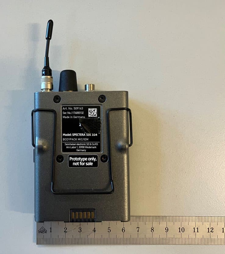
DMOSEK1G4
Mar 11, 2026Bodypack Mic/IEM
Equipment Class
TLD - Licensed LPAS Device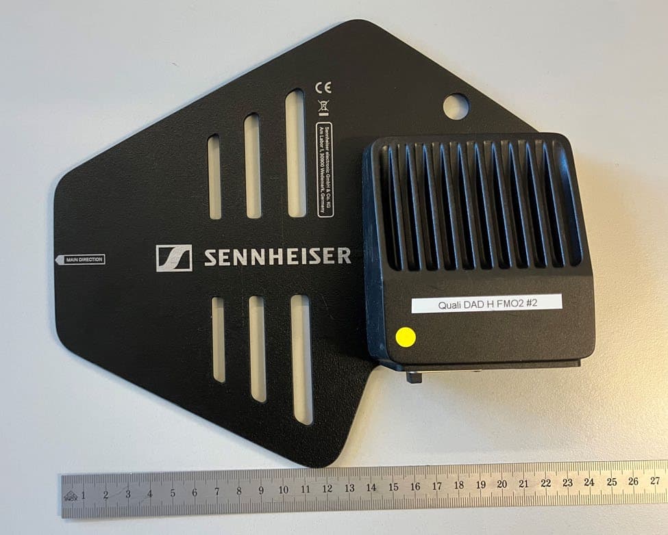
DMODAD1G4
Mar 11, 2026Antenna Transceiver
Equipment Class
TLD - Licensed LPAS DeviceDMOTSEWDX
Jan 30, 2024Wireless Table Stand
Equipment Class
TLD - Licensed LPAS Device